Balanced line Tuner
A much better way of getting an antenna to work on many bands is to use balanced tuned feeders with a doublet.
This is far less critical then the dipole/coax arrangement (you don't need to do the dip) because with
a doublet only balance is important. When coaxial cable is of the same impedance as the antenna (unlikely), the
cable is matched to the load and the line is said to be flat. An alternative to the flat line is the
resonant line; when the line has an impedance that is different to that of the load. The open wire line
shows low loss when used for this.
Some kind of antenna (or feeder) tuner is then required with a balanced line output. Here is example
of such a tuner constructed for 15m and 10m only.
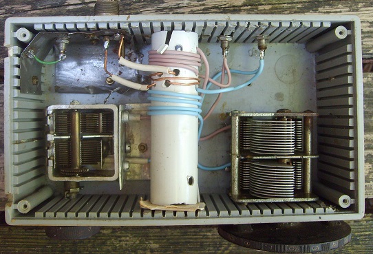 Heavy gauge wire is used and no switches. The coil should be kept a few diameters away from metal.
Perhaps the input winding could be wound with coax input as shielded loop? The 4t+4t are wound in the same sense.
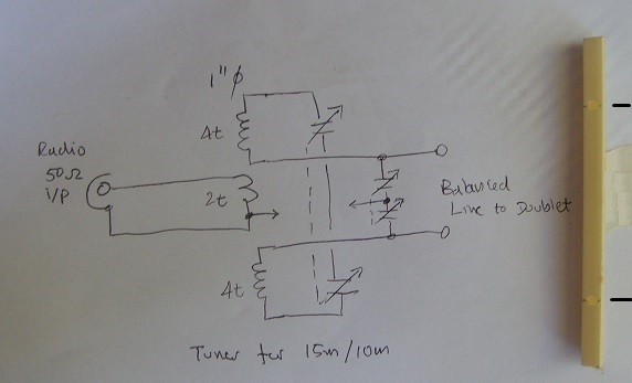
And the circuit:
Heavy gauge wire is used and no switches. The coil should be kept a few diameters away from metal.
Perhaps the input winding could be wound with coax input as shielded loop? The 4t+4t are wound in the same sense.
And the circuit:
 The ground connection between input and output was NOT made in the constructed unit.
The plastic on the right is part of a A4 sheet clip predrilled for the balanced line;
two insulated wires thread through each spacer. Half of mains zip wire is used, quality wire having
diameter of about 1mm and spaced here spaced 60mm for line impedance of perhaps 580 ohms.
The ground connection between input and output was NOT made in the constructed unit.
The plastic on the right is part of a A4 sheet clip predrilled for the balanced line;
two insulated wires thread through each spacer. Half of mains zip wire is used, quality wire having
diameter of about 1mm and spaced here spaced 60mm for line impedance of perhaps 580 ohms.
 Ensure the balanced line comes from the antenna at a right angle (natural with horizontal antenna
and vertical feeder) for some distance. Avoid right angle bends in feeder. Keep feeder a few
line spacings away from any metal. And include a few gentle twists...
Avoid low impedance (resistive part) antenna with this arrangement because losses increase;
A DXZ (0.64+0.64 on 10m) is 12.8m long , and this at 15m is 0.4 + 0.4 wavelength.
Keeping to a maximum of 0.64 each side of feedpoint ensures azimuth pattern doesn't split up.
different antenna arrangements produce different feedpoint impedances (calculated with EZNEC):
# 6.6m+6.6m height 20m up
28.5 172-775
24.95 632-1855
21.2 4039+1050
# DXZ 6.4m+6.4m at height = 10m
28.5 260-1035
24.95 1359-2087
21.2 3395+2481
The problem with balanced line tuner is coping with reactances seen at line input.It is generally suggested just to
'insert another length of feedline' to cope with stubborn matching conditions, this not being practical with open wire line,
the equivalent line could be comprised of lumped components instead? One method shown here is to ensure that the reactance
is always +ve looking into the feedline. In the picture of the tuner shown above, the variable capacitor across the feedline
copes with the situation where the reactance seen looking into the feedline is +ve., (the capacitor shown could be smaller
in value or series capacitors included to reduce range).
for the 6.6m+6.6m at 20 m height with 450 line
4 # 6.6m+6.6m height 20m up, feeder 30.8 m
28.5) Rin 55 Xin 141 (151 ohms) loss=0.77dB
24.95) Rin 60 Xin 328 (333 ohms) loss=0.93dB
21.2) Rin 128 Xin 519 (535 ohms) loss=0.59dB
this length of feeder provides Xin always +ve
for the 6.4m+6.4m at height = 10m with 450 ohm feeder
2 # DXZ 6.4m+6.4m at height = 10m, feeder 12 m
28.5) Rin 51 Xin 196 (202 ohms) loss=0.36dB
21.2) Rin 183 Xin 817 (837 ohms) loss=0.3dB
again Xin always +ve
If however the feedline tuner is happier seeing capacitative line input, capacitance can be inserted into line at tuner.
For example two short length of coax (one in each side of feed line, braid connected to tuner, inner conductor to feedline) could
be used. capacitors of 50pf (a half metre of coax) would provide 900 ohms at 40m and 450ohms at 20m for the case where the reactance
seen into line is +ve. Another suggested method is to install relay switch at antenna feedpoint that with +ve voltage on feedline
could add capacitance or with -ve voltage feedline inductance at feedpoint.
To use this short antenna on 40m with low loss, 600 ohm line might be used (with a multiband tuner)
600 ohm line, VF=0.92, loss at 1Mhz 0.02 and 10Mhz 0.06 dB/100ft
(note that a VF of 0.97 is more usual for this 600ohm homemade line)
7 # DXZ 6.4m+6.4m at height = 10m, feeder 12 m
28.5) Rin 81 Xin 280 (291 ohms) loss=0.2dB
24.95) Rin 168 Xin -633 (655 ohms) loss=0.14dB
21.2) Rin 234 Xin 887 (918 ohms) loss=0.16dB
18.1) Rin 74 Xin -99 (123 ohms) loss=0.12dB
14.15) Rin 1143 Xin 1518 (1900 ohms) loss=0.08dB
10.1) Rin 104 Xin -475 (486 ohms) loss=0.11dB
7.15) Rin 63 Xin 1218 (1219 ohms) loss=0.78dB <- 600 ohm line reduces losses
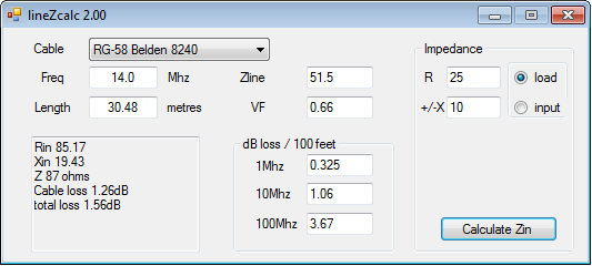
program for .net 3.5 lineZcalc2.zip
Ensure the balanced line comes from the antenna at a right angle (natural with horizontal antenna
and vertical feeder) for some distance. Avoid right angle bends in feeder. Keep feeder a few
line spacings away from any metal. And include a few gentle twists...
Avoid low impedance (resistive part) antenna with this arrangement because losses increase;
A DXZ (0.64+0.64 on 10m) is 12.8m long , and this at 15m is 0.4 + 0.4 wavelength.
Keeping to a maximum of 0.64 each side of feedpoint ensures azimuth pattern doesn't split up.
different antenna arrangements produce different feedpoint impedances (calculated with EZNEC):
# 6.6m+6.6m height 20m up
28.5 172-775
24.95 632-1855
21.2 4039+1050
# DXZ 6.4m+6.4m at height = 10m
28.5 260-1035
24.95 1359-2087
21.2 3395+2481
The problem with balanced line tuner is coping with reactances seen at line input.It is generally suggested just to
'insert another length of feedline' to cope with stubborn matching conditions, this not being practical with open wire line,
the equivalent line could be comprised of lumped components instead? One method shown here is to ensure that the reactance
is always +ve looking into the feedline. In the picture of the tuner shown above, the variable capacitor across the feedline
copes with the situation where the reactance seen looking into the feedline is +ve., (the capacitor shown could be smaller
in value or series capacitors included to reduce range).
for the 6.6m+6.6m at 20 m height with 450 line
4 # 6.6m+6.6m height 20m up, feeder 30.8 m
28.5) Rin 55 Xin 141 (151 ohms) loss=0.77dB
24.95) Rin 60 Xin 328 (333 ohms) loss=0.93dB
21.2) Rin 128 Xin 519 (535 ohms) loss=0.59dB
this length of feeder provides Xin always +ve
for the 6.4m+6.4m at height = 10m with 450 ohm feeder
2 # DXZ 6.4m+6.4m at height = 10m, feeder 12 m
28.5) Rin 51 Xin 196 (202 ohms) loss=0.36dB
21.2) Rin 183 Xin 817 (837 ohms) loss=0.3dB
again Xin always +ve
If however the feedline tuner is happier seeing capacitative line input, capacitance can be inserted into line at tuner.
For example two short length of coax (one in each side of feed line, braid connected to tuner, inner conductor to feedline) could
be used. capacitors of 50pf (a half metre of coax) would provide 900 ohms at 40m and 450ohms at 20m for the case where the reactance
seen into line is +ve. Another suggested method is to install relay switch at antenna feedpoint that with +ve voltage on feedline
could add capacitance or with -ve voltage feedline inductance at feedpoint.
To use this short antenna on 40m with low loss, 600 ohm line might be used (with a multiband tuner)
600 ohm line, VF=0.92, loss at 1Mhz 0.02 and 10Mhz 0.06 dB/100ft
(note that a VF of 0.97 is more usual for this 600ohm homemade line)
7 # DXZ 6.4m+6.4m at height = 10m, feeder 12 m
28.5) Rin 81 Xin 280 (291 ohms) loss=0.2dB
24.95) Rin 168 Xin -633 (655 ohms) loss=0.14dB
21.2) Rin 234 Xin 887 (918 ohms) loss=0.16dB
18.1) Rin 74 Xin -99 (123 ohms) loss=0.12dB
14.15) Rin 1143 Xin 1518 (1900 ohms) loss=0.08dB
10.1) Rin 104 Xin -475 (486 ohms) loss=0.11dB
7.15) Rin 63 Xin 1218 (1219 ohms) loss=0.78dB <- 600 ohm line reduces losses
program for .net 3.5 lineZcalc2.zip
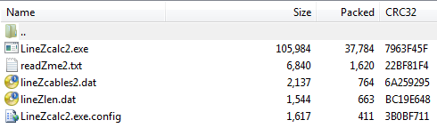
 in zip:
 The feeder lengths shown above are examples calculated from the program.
Example Example calculations for ZS6BKW
Reference
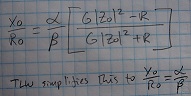
QST Aug '95 p79 mentions Reference Data for Radio Engineers 5th Edition page22-3.pdf
and suggests this formula:
The feeder lengths shown above are examples calculated from the program.
Example Example calculations for ZS6BKW
Reference
QST Aug '95 p79 mentions Reference Data for Radio Engineers 5th Edition page22-3.pdf
and suggests this formula:
 Notes
'insert another length of feedline'
Notes
'insert another length of feedline'
 A really good idea (from https://web.archive.org/web/20210212170518/http://w5dxp.com/notuner/notuner.HTM )