
Navigation
Menu
Center-fed Bent-Dipoles
Horizontal Lateral
Vertical
- OCF
Slow-Wave
Other Topics
Home
With antenna modeling software it is possible to answer the "What if...?" question about bending a dipole. With the program 4NEC2, which has an optimizer function, it becomes easy to automatically answer the question for any angle of bend up-or-down.
 What
Happens If...
What
Happens If...You Bend a Dipole in the Middle?
We start with a tuned Standard Dipole of #14 wire mounted horizontally and fed in the center at 1/2 wavelength elevation. The left arm is fixed. The right arm can be swung up or down at any angle.. The study here involves first setting an angle then running the optimizer. The model then tries different values until it converges on the optimal length of the variable arm for lowest SWR 50 and reactance (X-in). The calculated results are Gain, SWR, Efficiency, Impedance, Radiation Angle, Bandwidth at half-power points and validation by Average Gain Test (AGT). All this information and more is recorded in 15° increments.
4NEC2 Antenna Model: Here
In Figure 1 below are selected the usual parameters of most interest, Gain and SWR. To more completely answer the "What if..." question, the curves are extended to SWR 2.0. Even at those points at the extreme ends remain valid therefore usable according to the AGT.
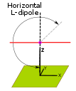
To make clear what the angle of bend looks like, images of the bent dipoles are placed in red just above the angle indications.
The -30° mark indicates an overbend past straight down (0°). The 90° mark is the straight horizontal dipole. 210° is an overbend beyond straight up (180°).
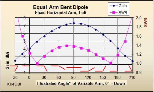
Figure 1
A graphic indication of the L-bend is shown in red.
Looking at the general shape of the curves in Figure 2 below, you will notice they are not symmetrical on either side of 90° depending if the variable arm goes toward (down) the ground... or away (up).
Following the SWR (Pink) line from 90°, it actually gets higher at 75° then falls off rapidly to a sharp minima at 15°. At the 0° (Inverted-L) configuration or the 180° (L-antenna) configuration, the impedance is around half that of a dipole and rises rapidly thereafter.
Similarly, when bending a dipole upward, the SWR is lowest at 165°, 15° from straight up. At the lowest SWR points at 165° and 15°, the gain is 5 dBi compared with 7.32 dBi for a 90° straight Dipole. This seeming loss can be seen as a benefit. In the L-form, the antenna performs both as a normal vertical antenna and as well as a dipole with reduced gain.
These combined Horizontal/Vertical characteristics are desirable where local contacts may be with hams with either type of antenna polarization. Also, QSB in DX signals can also rise from polarization changes in signals bouncing off of ionized layers. The mixed polarization of the L-antenna form is thought to smooth out some of that effect.
Radiation
Efficiency and % Change in Resonant Length
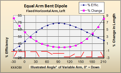
Figure 2
A graphic indication of the V-bend is shown in red.
A horizontal center-fed dipole is the most efficient antenna form. Bending will reduce efficiency and shorten the radiation length causing the frequency to rise. It therefore is necessary to lengthen the antenna appropriately to maintain resonance. The pink curve above represents the modeled percentage increase in straight antenna length to be resonant when the wire is bent to the angle indicated.
Note also that the curves are not symmetrical. Efficiency falls more rapidly as the variable arm nears ground, to 47% efficiency as an inverted-L form versus 57% efficiency as an L-antenna.
Far Field Radiation Patterns
In Figure 3, let's look at the Graph and 3D picture as the variable arm is pointing downward in the inverted-L form.
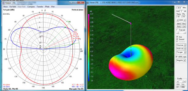
Figure 3
On the circular graph, the gain (red line, looking down) is 4.27 dBi at the top and bottom (which is to the sides of the horizontal arm). Recall that the standard dipole has 7.32 bBi gain. The dent to the left is -4.7 dBi so the null where the horizontal arm points is 9 dBi. less than the gain to the sides. Opposite the side arm there is zero gain so it is basically a vertical antenna in that direction.
Looking from the side (blue line), the maximum power lobe peak is at the 65° mark down (or 25° up) . The half-power (-3 dBi) beam-width (green) is 35° wide.
Looking at the 3D view from above note the position of the antenna relative to the maximum signal in red and purple. Note also the minimum signal in blue is under the horizontal arm.
In Figure 4, we look now at the L-antenna form where the variable arm is pointing upward.
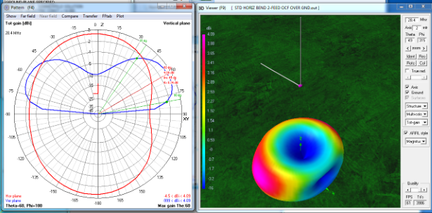
Figure 4
On the circular graph, the gain (red line, looking down) is 4.09 dBi at the top and bottom (which is to the sides of the horizontal arm). Recall that the standard dipole has 7.32 bBi gain. The dent is now swaps sides to the right and measures -4.5 dBi so the null points away from the horizontal arm. The signal difference from the sides is 8.6 dB, slightly less than the inverted-L. The horizontal arm points at zero gain so the L-form is basically a vertical antenna in that direction with gain on either side.
Looking from the side (blue line), the maximum power lobe peak points 5° higher than the inverted form, at the 60° mark (or 30° up) . The half-power (-3 dBi) beam-width (green) is 10° wider, or 45° wide.
Because of the directional pattern, some consideration should be made as to how to orient the side arm for practical use of a L-antenna. The side arm hemisphere will be noticibly louder for reception and transmission than the opposite side.
Note: If an identical arm is added directly opposite the first arm, the current in the two arms balance and the radiation pattern is only a slightly oval shape. Adding two more opposing arms at 90° forms a typical vertical antenna having circular radiation pattern. A word of caution: If there is anything that detunes one or more of the arms, the current will flow to the most resonant arm or arms and the pattern will again be directional. If there is any question about balance and you do not have an RF ammeter, check if your pattern is not round is by rotating the antenna while listening.
Dick Reid, KK4OBI