
Navigation
Menu
Center-fed Bent-Dipoles
Horizontal Lateral
Vertical
- OCF
Slow-Wave
Other Topics
Home
From the OCF Impedance study it is found that the proper length of #14 wire bent 40% vertically and 60% horizontally gives close to a 50 Ohm match at 1/2 wavelength high feedpoint. The question is...
What happens when you change the angle
of a 0.4 OCF Wide L-Dipole?
of a 0.4 OCF Wide L-Dipole?
To answer this question a generalized OCF antenna model was developed where where any length of wire could be bent at any point and each arm could be set at any angle. For this study the long arm is fixed vertically and the angle of the shorter side arm is adjusted upwards in 15� increments starting from a vertical OCF dipole. At each angle the optimizer function of the model evaluates the the results for SWR and reactance +/-j, adjusts the length of the wire and repeats the model until the best SWR and reactance values are found.
4NEC2 Antenna Model: Here
Figure 1 summarizes some key results of this 0.4 bend ratio antenna model study.
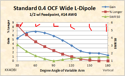
Figure 1
Representations of the angle of bend are shown red..
Read: maximum bend at the left; a vertical dipole is at the right at 180�.
Consider also that the Long arm is toward the ground. Because of this off-centerness the impedance is slightly higher than a center-fed configuration... around 75 Ohms or a SWR 50 about 1.5 : 1. Follow the Green SWR 50 curve from 180� and see it steadily drop to 1:1 SWR at 90�. Beyond that the SWR begins to rise rather rapidly.
When a resonant straight wire is bent it becomes shorter causing the frequency to rise. To maintain the desired tuning, the wire must be longer. The red line tells how much % Longer. For example, to stay on frequency at the sweet spot of 90�, the wire must be 2.4% longer than the 180� vertical.
Gain (Blue line) starts at 1.3 dBi for this 0.4 OCF vertical dipole. On Figure 1, follow the line to the left.
Notice that around 135� the Blue line starts to rise more rapidly as the longer lower arm gets closer to horizontal. It is starting radiate more horizontally. At 90� the Wide L-dipole has a SWR very close to 1:1 and has 5.9 dBi gain and is 40% shorter than a half-wave dipole.
The interesting thing is that as the long arm rises above horizontal, gain continues to increase.
In spite of the odd shape created, it radiates almost exactly like a dipole as the angle approaches 60�, ie. 30� above horizontal. The Gain at that point is 6.9 dBi which is very close to the 7.3 dBi of a full half-wave dipole at the same feedpoint elevation. The trade-off is impedance. At 60� the impedance has dropped to around 30 Ohms giving a SWR of 1.7:1. It advisable to keep the side arm no more than 15�-20� above horizontal to balance high gain and low SWR.
To get gain the radiation pattern must be concentrated. The key factor here is matching coaxial cable by altering an L-antenna so only 40% is vertical and lengthening the side arm to 60%... making it wide... more dipole like. Lets take a look at the radiation pattern of a OCF vertical dipole before bending it.
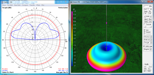
Figure 2
OCF vertical dipole fed 0.6 from bottom.
Looking at the circular graph in Figure 2, notice the lobes (Blue trace) at 35� and 75�. In the 3D view it looks a like a blue donut on the red disk. In a center-fed vertical dipole you see only one smooth large lobe... no donut. In this OCF vertical dipole Gain is less, 1.3 dBi versus 1.4 dBi . SWR is higher, 1.5 versus 1.4.
Now let us look how much the pattern changes in the Wide L form.
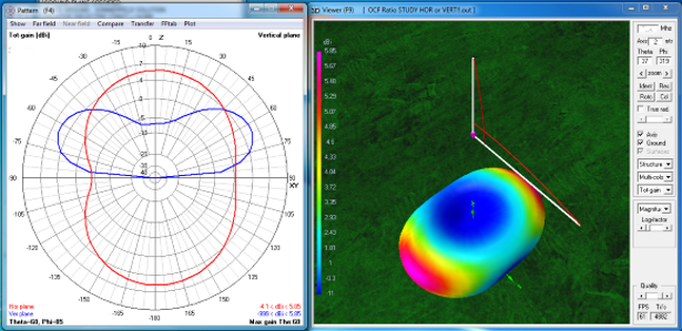
Figure 3
OCF Wide L-antenna, 90� side arm
The thing that jumps out in Figure 3 is that the radiation pattern looks very much like a half-wave dipole. On the circular graph red trace, the only difference is that the usual null on the right is filled in by radiation from the side arm. Compared to a dipole, Gain is less, 6.6 dBi versus 7.3 dBi. SWR is better, 1.02 versus 1.4. Length is 40% shorter.
Now let us look how much the pattern changes in the Wide L form with the side arm 30� higher.
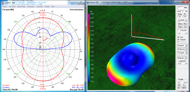
Figure 4
OCF Wide L-antenna, 60� side arm
With the side arm 30� above horizontal, the change in Figure 4 is in the nulls (as seen in the red trace). We now have a dipole null on the right, but less null on the left. The side arm was raised a little too far for a symmetrical dipole radiation pattern. Also there is slightly more vertical radiation (blue bump in the middle) than seen in a dipole. A good compromise would have the side arm around 75�(15� above horizontal).
Comparing this 60� Wide L-antenna to a dipole: Gain is 6.9 dBi versus 7.3 dBi. SWR is 1.7 versus 1.4. Wire is 5.35 % Longer. Signal reduction between side and end null is 10.3 dBi.
Comparing the 75� form to a dipole: Gain is 6.6 dBi versus 7.3 dBi. SWR is 1.3 versus 1.4. Wire is 5.29% Longer. Signal reduction between side and end null is 11.3 dBi.
This is an acceptable half-wave dipole substitute at only 0.6 long and 0.4 high.
Addendum
Picture the above Wide L-Antenna at 75�, only with a second identical side arm at a right angle to the first side arm. The center coax wire is attached to the vertical arm. Imagine a remote switch so you could switch your coax ground connection back and forth between the side arms.
Compared to a conventional half-wave dipole: Gain is 6.5 dBi versus 7.3 dBi. SWR is 1.3 versus 1.4. Wire is 5.29% Longer. Signal reduction between side and end null is 11.0 dBi.
This arrangement provides a way to have North-South or East-West coverage by a flick of a switch.
Dick Reid, KK4OBI at QSL.net