Introduction To The Project
This page gives details of the construction of my dual band inverted V antenna for 40 & 80m. Since moving to a property with a large garden, I was able to erect a full size inverted V for 80m, and decided to incorporate elements for a 40m inverted V at the same time. Both antennas would be fed from the same feedpoint to reduce the number and therefore cost of feedlines, and the intention was to incorporate a choke balun at the feedpoint to force balanced operation of the antennae, despite being fed with unbalanced feeder.
I had already decided on the type of support pole I was going to use, and this was one supplied by Knights Electrocom. It comes as 1.5 metre sections with one end swaged to a smaller diameter, allowing the sections to be stacked together to make a longer pole. One problem I had identified from previous experience was the tendency of the pole to gradually sink into the ground under its own weight over time, causing the guys to become slack and as the ground in this location is particularly soft, I decided to take measures to avoid this.
How the base was made |
Cast base in situ |
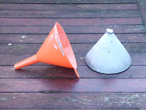
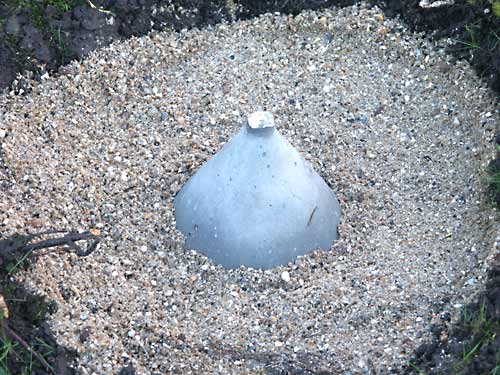
The solution I arrived at was to create a foundation of sorts by filling a funnel with quick-setting cement, in order to cast a solid conical base on which the mast pole could sit. The concrete cone was then bedded in the ground using gravel at the appropriate location. The photos above show the casting of the cone and the way it was placed on the ground, the idea being that the aluminium tube would sit centrally on the cone which would not only locate it, but prevent it from sinking into the ground.
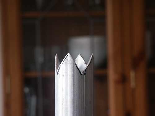
Being 800 feet above sea level and somewhat exposed, a lightning strike to the support mast was a distinct possibility so the topmost section of mast had sections cut from the top to form a series of spikes at the very top in the hope that it would function as a lightning conductor. Apparently the object of a lightning conductor isn't primarily to conduct a direct strike to ground (although obviously it would need to be able to do this without being damaged) but rather to gradually discharge the cloud above, hopefully avoiding a strike at all.
The lightning tip |
The choke balun |
I've placed a photo here of what I did to the top tube, which will hopefully allow it to perform as an air terminal. The plan was to place copper earth rods at the base of the mast and connect the base of the tubes to these earthing rods to the earth stakes using thick copper cable, allowing a very low impedance path from the tip of the mast to the ground.
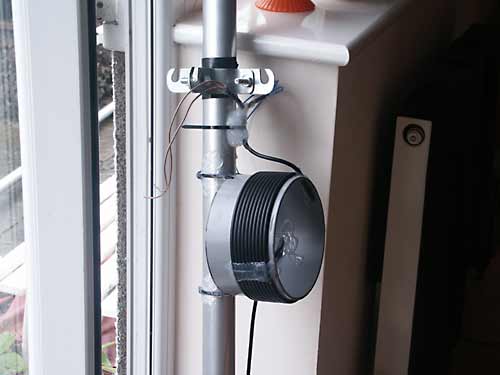
The next job was to fit guy supports to the top section and the choke balun, this assembly shown in the right-hand photo above. This was all fitted a couple of feet below the tip for some protection from a direct strike. Due to the overall length of the assembled mast, I decided it would be wise to attach guys to the middle of the assembly too, to stabilise everything as there would be a tendency for the centre to whip about uncontrolled in the wind, so the necessary hardware was fitted at this point too.
Now I needed to prepare the wire elements. I was quite lucky many years ago to have had the opportunity, shall we say, to obtain some old telegraph wire made of cadmium/copper alloy as was used for bare wires at the time. Such wire is almost as conductive as pure copper, but a heck of a lot harder. Initially the wire lengths for the elements were guessed at; it's possible to roughly calculate what these lengths should be, but as there are so many variables such as nearby objects and ground proximity, the calculated dimensions are rarely close to real life. So, I guessed.
The elements for both bands ended up being rather longer than required and a lot of lowering and raising of the antenna was done before I was happy. The longer 80m elements were trimmed first, and once I was happy (very happy actually - almost unity VSWR at the target 3.740MHz) I dealt with the 40m elements. Trimming these shorter elements made no discernable difference to the tuning of the 80m elements, which was helpful.

Top of the erected antenna showing hardware
The photo above is a shot of the top of the final erection, standing at about 50 feet tall, showing the choke balun, guys, insulators and wire elements. The insulator arrangement at the outer tips of the elements is worth a mention: Rather than terminating each element at the insulators, a 'pig tail' of wire about 15 inches or so long was attached to extend beyond the insulators, flapping about in mid-air. I see two benefits to doing this - firstly it makes final trimming of the antenna very simple and secondly it removes the very tip - the highest impedance section of the antenna and therefore the part with the highest voltage, away from the insulator. This second point may be of no significance, but it makes me happy.
Below is a diagram of the entire dual-band antenna with the element measurements. As can be seen, the 40m elements are inclined more steeply than the 80m ones, and have their own ground supports closer to the base of the mast. This makes it quite easy to vary the angle to optimise impedance matching. The 80m element angle was more down to luck as the height of the mast was predetermined as was the size of the garden I had available to fit it in. As it happened, it tuned up really well and the results are impressive for both bands, certainly the best I have constructed so far.

Diagram of the antenna with dimesions
This antenna with the element lengths and attachment points indicated resulted in an 80m antenna with its tuning being centred around 3.740MHz with an almost unity VSWR. The 40m section was resonant at roughly 7.1MHz also with an almost unity VSWR. The centre point of tuning can of course be modified to suit individual preferences. It should be noted that the outer ends of the 80m element supports were attached to trees at a point roughly 2 metres above the ground. I haven't worked out the actual angles of the elements, I'll let someone else do the trigonometry if they feel so inclined!