
Introduction
I have many odd interests, and this is certainly one of them. Few people are aware of the presence of naturally-occurring Very Low Frequency (VLF) radio signals and earth currents, and probably even fewer care about it. However, some people have a keen interest in the phenomena and actively pursue the recording and logging of anything interesting they detect.
Very Low Frequency is the official name given to the part of the electromagnetic spectrum which extends from 3KHz to 30KHz; for the purposes of this page, I'll incorrectly refer to anything that falls into the range of human hearing to be VLF including sounds down to 200Hz and below.
The large range of signals which may be heard in a VLF receiver can initially be divided broadly into two classes, dealt with in the next sections.
Signals Of Man-made Origin
Technology leaves its imprint on the VLF spectrum, and these signals form part of what can be received.
Mains Hum
This is caused by fields radiated from the mains electricity supply lines, known in the U.K. as the National Grid. These alternating fields have a fundamental frequency of 50Hz in this country, and unless steps are taken to site the receiving equipment in a remote location, the interference they generate will form the bulk of what is detectable and can present a major obstacle to detecting the fainter, natural signals. It is relatively easy to filter out the fundamental, but the higher harmonics can still present problems, extending as they do well into the audible range.
Received mains hum waveform showing a high fifth harmonic content
Above is shown 4 cycles of mains hum as detected by my receiver, in this case showing a very high fifth harmonic content (250Hz), along with a lot of other noise. Note that this is what was left after the 50Hz fundamental had been reduced in strength by filtering; the state of the mains power isn't as bad as the graph might suggest!
This kind of power pollution is generally blamed on modern electronics and the fifth harmonic in particular can be problematic as it can cause additional heating of transformers and motors, and can possibly cause other problems by exciting resonances which the fundamental itself wouldn't do; quite apart from this, it makes the hobby of VLF listening rather more difficult.
VLF Radio Transmissions
Radio transmissions in the VLF part of the electromagnetic spectrum manifest themselves as frequencies generally above the hearing range of humans, and are encoded using a small frequency shift to carry data, known as minimum-shift keying or MSK. I understand that these signals are for communication to submarines, as transmissions at frequencies this low can penetrate for several metres below the sea meaning the submarine doesn't need to surface to receive them.
A sonogram of VLF data transmissions, probably intended for submarines
The sonogram above shows at least 13 data streams in progress at the time of this 2-second capture, each transmission represented by a horizontal wavy line. The frequency scale is vertically on the Y axis, covering between 17KHz and 44KHz and the time scale is along the X axis, spanning the 2 seconds; there were no transmissions detectable below this at the time. The vertical components are atmospherics of natural origin.
The signal around 22·6KHz can be seen to be particularly strong, and reducing the intensity of such signals, assuming they are of no interest, may be in order as at times they may be so powerful as to overload parts of the equipment causing audible intermodulation products which sound rather like a telephone modem, if you have enough barnacles around the belt to know what that sounds like. A good measure of filtering is recommended, and field tests have shown that a second-order filter providing -16dB of cut at 20KHz is the bare minimum requirement at my location.
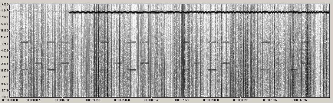
More VLF data transmissions, this time possibly navigation signals
The above sonogram shows a 14 second capture revealing unidentified transmissions consisting of short tone bursts on three distinct frequencies of approximately 12KHz, 12.75KHz and 15KHz, apparent on this graph by the four repeating patterns of seven horizontal dashes; inaudible to me, but most teenagers and ladies would probably be able to hear them. I understood that all the VLF navigation stations had ceased operations, and yet this, recorded in October 2025 appears to show exactly that. The dark jagged line near the top is the signal from a strong VLF data station which started transmitting during the capture period, and as before, the vertical lines are atmospherics of natural origin.
Signals Of Natural Origin
Signals resulting from natural phenomena are many and varied, with various theories devised to explain them; many conveniently fall into the audio range, making it relatively simple to detect them.
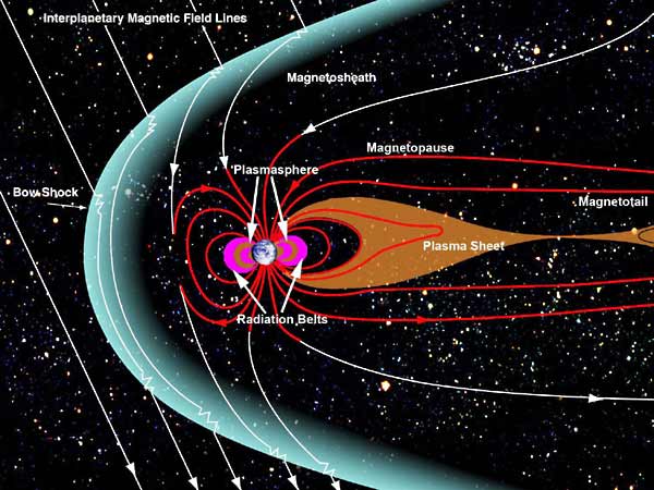
A diagram of the Earth's magnetosphere
Credit: NASA
Our planet, Earth, generates a magnetic field around it known as the magnetosphere, and this is known to extend for a minimum of around a quarter of a million miles out into space, but as the diagram shows, the solar wind distorts the shape of this field in such a way that it is dragged out behind the Earth in a direction away from the Sun, and in this direction extends for well over two million miles. This 'force field' surrounding the earth represents one of the ingredients for some interesting effects.
It has been estimated that as many as a thousand thunderstorms are active in the atmosphere at any one time, and each of the lightning strikes releases a huge amount of electromagnetic energy which ranges in frequency from a few hertz right up to light and beyond, and these discharges are responsible for the constant crackling heard in a VLF receiver.
If the conditions are just right, these lightning-initiated radio bursts may leave the planet and propagate for an enormous distance around the magnetosphere, and by various means return some seconds later, exhibiting a degree of frequency separation in much the same way as light passing through a prism is split into an ordered spread of frequencies, or colours. This frequency splitting can result in some interesting phenomena, which can be heard with the appropriate equipment.
Most of the naturally occurring signals can be classified according to how they sound:
Atmospherics
Sometimes abbreviated to 'sferics', these signals form the bulk of the soundscape and sound rather like the crackling of a bonfire. Caused by multiple lightning strikes around the world, this is present at all times to some degree, and hearing this indicates that the receiver is working. The recording below is typical of what you should be able to hear, and was made using the equipment detailed further down the page.
7 seconds of atmospherics
Tweeks
These are the sounds of lightning strikes which have undergone a form of frequency separation due to the considerable distance they have travelled around the planet, and rather than a simple click, the sound has been split so that the lower frequencies arrive a fraction of a second later, exhibiting a characteristic 'pew pew' sound. Tweeks are relatively common and often tend to become noticeable within the atmospherics as dusk approaches, although it can take a while and many trips before finally capturing some good examples.
7 seconds of atmospherics with some tweeks
Whistlers
One of the odder sounding signals, these eerie noises are again believed to be the result of a lightning discharge, but this time the signal consists of a breathy sound falling in frequency; whistlers are not particularly common and conditions need to just right for them to be generated and heard, but with patience, good examples can be captured.
5 second recording with one quiet whistler
Stephen P. McGreevy described very well how whistlers are thought to originate:
"Some of the radio energy bursts from lightning strokes travel into space beyond Earth's ionosphere layers and into the magnetosphere, where they follow approximately the lines of force of the Earth's magnetic field to the opposite polar hemisphere along ducts formed by ions streaming toward Earth from the Sun's Solar Wind. Solar-Wind ions get trapped in and aligned with Earth's magnetic field. As the lightning energy travels along a field-aligned duct, its radio frequencies become spread out (dispersed) in a similar fashion to light shining into a glass prism. The higher radio frequencies arrive before the lower frequencies, resulting in a downward falling tone of varying purity."
- McGreevy (1997)
The radio energy burst can on occasions be ducted back into the magnetosphere twice or more, creating longer delays and greater dispersion; multiple 'hops' have been detected, amounting to considerable delays in the received signal.
This brings to mind reports on 'long delayed echos' from the early 20th century, where echos of high powered Morse transmissions were heard with a delay of typically 3 - 15 seconds; alien orbital probes notwithstanding, this suggests to me that the transmissions may have been ducted around the magnetosphere back to Earth with the resulting delay. As the transmission was a single frequency, no dispersion would have happened as happens with whistlers.
Stephen McGreevy has a lot more to say on natural VLF phenomena generally, and I recommend having a read of his paper which can be found here:
The VLF Listener's Handbook
How I Got Interested In VLF Phenomena
I'm no expert in natural VLF phenomena, but I enjoy the opportunity to set up my home made detection equipment somewhere away from built up areas and to just sit and listen to the variety of sounds, waiting for that really unusual one to come along. I find it quite relaxing, a similar effect perhaps to listening to the sound of the sea or a stream, and I understand that my wife finds it quite relaxing too, as it gets me out from under her feet. I always have my recording laptop with me on VLF listening expeditions just in case some interesting conditions are underway.
I first became interested in these natural VLF signals in the early 1990s when I accidentally stumbled across them while conducting experiments in earth current communication. I had initially read about this idea in a copy of Electronics Today where the article mentioned how bases were set up during the First World War for secret communication between the trenches, and I found the technique interesting enough to attempt it myself.
Without going into too much detail, an audio signal is fed into the ground via two earth stakes set some 25 metres or so apart, and the signal can be received some distance away by using another pair of electrodes and some amplification.
During a period of excessive enthusiasm I actually built a self-contained earth current transceiver. The receiver side consisted of the necessary amplification to receive earth signals and the transmitter consisted of a CB microphone feeding a home-made audio amplifier driving a step-up transformer to provide a better match to the moderate resistance existing between the probes.
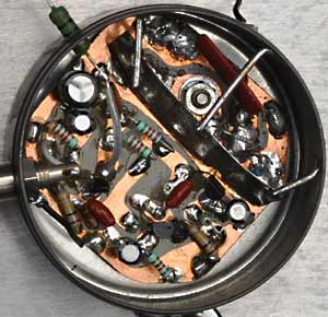
The line level transformer I used
AA battery for scale
The transformer used was a bit of a beast, being a 500 watt 4Ω to 100 volt 'constant voltage' audio line transformer and weighing in at a lumpy 3·7Kg; it was massively oversized for the small job in hand, but it was audio grade and in my possession, which was useful.
The 4Ω winding was made up of 4 separate windings connected in series-parallel, so I separated them and added 2 of the windings in series with the secondary to increase the turns ratio, and the remaining 2 connected in series to form a centre-tapped primary. This was fed by a pair of matched 2N3055 transistors operating in push-pull to form the output stage of a crude class B-ish amplifier.
After the modification, the turns ratio was roughly 1:7, meaning that a 392Ω resistance, for example, would be reflected back to one half of the primary as a resistance of 8Ω. (Resistance divided by the square of the turns ratio: 392 ÷ 49.) A higher turns ratio would have allowed more power to be produced, but this was a dedicated audio transformer and I used what I had.
The whole assembly was switched between receive and transmit by a relay operated by the PTT button on the microphone which worked perfectly. The bulk of the resistance between the probes was due to contact resistance between the probes and the soil, and although variable, typically measured a few hundred ohms. A 330Ω resistor connected in place of the earth probes would heat up nicely on transmit showing that the impedance match wasn't too pathetic. The audio had a fair bit of distortion, but the transmitter was efficient and in any case this was only ever intended for communications work.
As I had 2 of these transformers, I'd like to have built another transceiver and to have persuaded a friend to chat with me through a hill, but I ended up building a dodgily-designed inverter which injected a tone of sorts into the ground, which I then attempted to receive.
As it happened, I managed to get a reasonable distance during the tests, perhaps a couple of hundred yards, but range was ultimately limited by the mains hum which masked the quieter audio signals; the system would certainly have done a lot better in a more remote location and with some high-slope filtering. I'm considering knocking up a pair of transceivers again, but this time incorporating filtering improvements I've developed along the way.
Although I can consider my earth current communication experiments to be a moderate success, I became more interested in an odd crackling sound which could be heard in the speaker, the origin of which I couldn't at that time explain as these signals evidently originated in the ground. I considered the possibility that it may have been voltages generated by the piezoelectric effect as deep-layered rocks underwent distortion and fracturing, and even contemplated the possibility that I may have been detecting the minute electric fields emitted by invertebrates living in the soil.
Further research revealed that this was actually the sound of natural atmospherics and my attention then began to turn to detecting these strange sounds in favour of further earth current communication experiments. For a while I used my home-built transceiver to receive these signals, but later started work on a dedicated receiver with better filtering to combat mains hum and VLF transmissions which had been causing some problems.
The Equipment I Now Use
The two easiest ways to detect these VLF signals are either by a pair of metal stakes driven into the ground which detect the current flowing which replicates the passing radio wave, or directly from the air using an antenna, which detects the electrostatic field. As these signals fall into the audible range, no frequency conversion is needed to hear them.
My early experiments used the earth current method but my listening attempts were always hampered by a high level of mains interference which proved difficult to get away from, although the filtering I used back then was mediocre at best. I turned my attention to trying to detect the electrostatic field of the radio waves using an antenna which offered a lower level of mains hum in most cases.
The antenna I use is an 8-foot CB whip; this seems to be about optimal, as anything significantly longer is likely to cause problems by overloading the front end of the receiver with long wave broadcast signals and VLF data transmissions, requiring some pretty aggressive filtering to remove them which will reduce sensitivity, rendering the use of a larger antenna fairly pointless.
I've seen plenty of weird and wonderful designs for VLF receivers on the Internet in recent times, and in most cases they are way more complicated than they need to be. A few appear to be theoretical only, with little chance of actually working in the field so are evidently untested and quite possibly AI-generated rubbish, so be a little bit careful when looking for VLF receiver ideas.
I recommend you avoid op-amps if possible, especially in the earlier stages and filtering. Such chips have a lot of active devices and very high open loop gain, and subsequently use a lot of negative feedback to keep things under control. Once interference finds its way into the feedback loop, intermodulation problems will likely ensue so any filtering should be passive, done before any op-amps if you choose to use them and certainly outside of any feedback loop.
I've gone into some detail with the circuits I ended up using as some may wish to re-create them, or modify them for their own use. This equipment initially used whatever components I happened to have to hand, but what I now use is the result of many years of trial, error and modification to get the results I wanted. The receiver was designed purposely using only discrete components (apart from the output module) and built in a modular manner: a pre-amp module, a filter module and the output module; this allowed easy modifications to be made, as tended to happen with monotonous regularity.
The 'Front End' or Pre-amplifier
Assembled preamp module, fitted inside an air rifle pellet tin
In essence, all that is required for receiving VLF signals is a reasonably sensitive audio amplifier, whether using earth probes or an antenna but better results can be had by optimising the input circuitry for the system used. An antenna, in particular, requires a very high input impedance for best operation, and for this an input circuit using a JFET would be a good design choice.
Such devices have an inherently high input impedance, low noise and simple associated circuitry. The transistor of choice for me was the good old 2N3819, cheap and still readily available as of 2025, this module using two of the devices; it has been designed to be suitable for both earth probes and an antenna.
This module is really the heart of the receiver, with the following sections being optional to a degree. The requirements for the first stage of this circuit were a high input impedance and moderate gain, exactly what a JFET offers; Q1 does double duty here by presenting the high input impedance and having moderate voltage gain, which is fed to Q2 which amplifies the signal further. Total voltage gain for this module came out at a surprising 100 times.
I constructed the module on a small piece of circuit board cut to fit inside an air rifle pellet tin, which provides excellent screening from the rest of the receiver. As the output is in phase with the input, the input circuitry west of Q1 was well screened from the rest to avoid feedback and instability problems. This unit incorporates some basic low-cut and high-cut filtering by design to slightly reduce mains hum and the impact of high intensity VLF data transmissions, before outputting the signal on to later stages.
Circuit diagram of the front end of the receiver
Bode plot of the preamp's response, showing gentle low and high cut
PREAMLIFIER CIRCUIT DESCRIPTION:
The incoming signal first encounters the neon lamp, which limits any voltages to around 60 - 90 volts, protecting the DC blocking capacitor which we'll come to next.
The 0·1µF 400 volt capacitor blocks any standing voltages which may be present, which could alter the bias point of the FET or even damage it. Such a voltage could occur when using ground probes (which I've measured at over a volt on occasions), and could also build up as static electricity on an antenna, particularly in dry weather.
The 47KΩ variable resistor and the four small switch-selectable capacitors form a first-order low-pass filter for eliminating radio station break-through. As the signal source impedance is unknown and variable, the filter characteristics can't be calculated, hence a range of options is provided: by selecting different capacitors and different settings of the variable resistor, a range of filtering combinations can be selected allowing for optimum filtering for any particular situation. Too much capacitance reduces the sensitivity and too much resistance results in the resistor's thermal noise becoming apparent, so a delicate balance needs to be found using the minimum of each.
The 10MΩ resistor is the usual gate resistor, required for biasing; leakage current through the FET's gate is miniscule, but can start to become significant when the gate resistor is made much higher than around 10MΩ, which can potentially render the bias point unpredictable. Using a higher resistance seems to make no difference to the receiver's sensitivity, so considering 10MΩ as a maximum would be reasonable.
The two opposing diodes are there to protect the FET's gate from high voltage transients, particularly those created by the striking of the neon lamp along with any voltage spikes below the lamp's strike voltage, and do so by limiting such spikes to around 0·7 volts; these could otherwise damage the transistor. Ideally ultra-low leakage diodes would be selected for this position in respect of the high impedance environment they are operating in, but the ubiquitous 1N4148 works well. For many years I ran the receiver without the neon lamp or diodes without incident, but their inclusion is probably a worthwhile safeguard considering they can probably be found in the junk box.
This unit incorporates some slight frequency response tailoring: the two 1000pF capacitors coupled with the output impedances of the FETs form basic high-cut filters which result in a response which is down by just over 4dB at 20KHz to reduce the degree to which VLF data transmissions are amplified, assuming these are of no interest. The relatively low value of the two 10µF source resistor bypass capacitors result in a rolling off of the low frequencies, also down by just over 4dB at 50Hz.
NOTES:
Tests have shown that at my location, 10KΩ in circuit followed by 47pF to ground eliminated all traces of radio station breakthrough when using an 8 foot antenna, without impacting sensitivity significantly.
Some ceramic capacitors can be slightly microphonic, and if used in the pre-filter can lead to acoustic feedback from the speaker at high volumes. The solution is to use film capacitors in this location.
FETs can under certain conditions break into oscillation; the usual remedy for this is to install a "gate stopper" resistor of a few hundred ohms as close to the FET's lead as possible to damp this tendency or bypass the gate to ground with a small value capacitor.
The Filter Section
Although the preamp module tailors the response somewhat by reducing the lower and the higher frequencies by a small amount, it has proved necessary to include a filter module with far steeper filtering to reduce the intensity of mains hum and VLF MSK transmissions which could otherwise cause problems.
The plan was to design a circuit comprising passive filter sections, which exhibited a reasonably flat passband between around 200Hz and 6KHz, and cut the level of 50Hz mains hum to one tenth (20dB) of the incoming level, and the same at 20KHz, with a steep attenuation slope beyond that.
The circuit I currently use uses 12 passive filters arranged in 6 sections, each section incorporating a low cut and a high cut, with each section being isolated from the next by a buffer stage to eliminate interaction between them. Combined, they provide an excellent frequency response for this application, with the -3dB points being around 150Hz and 6·4KHz and over 21dB of attenuation at 50Hz and 20KHz, better than I'd planned.
You could of course experiment with fewer or more sections than this, and also modify the filter component values to obtain different response curves. This circuit was modelled using LTspice, and while this free software does have its limitations, it does perform particularly well with passive RC filters. There is no substitute for a signal generator and oscilloscope for final testing, but simulators like this can save a lot of time at the design stage; real-world tests showed the circuit's operation to be very close to that predicted by the simulation, with just the overall gain being a couple of dB on the optimistic side.

Circuit diagram of the filter circuit showing the 6 cascaded filter sections

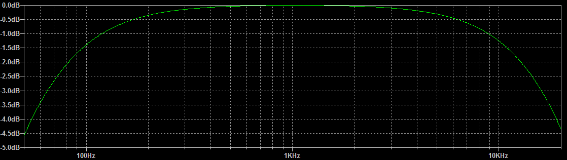
Bode plot of the filter board response
FILTER BOARD CIRCUIT DESCRIPTION:
The medium impedance signal from the preamp passes to the gate of Q1 which functions as a buffer, providing a high impedance input to the incoming signal and a low impedance output to drive the first of the six combined high and low cut filter sections. The 0.047µF capacitor the 68KΩ resistor provide a low-cut filter function with a cutoff of around 50Hz, with the 8·2KΩ resistor and 1000pF capacitor forming a high-cut filter with a cutoff of around 19.4KHz; these cutoff frequencies were chosen to provide decent attenuation at the target frequencies of 50K and 20KHz, while keeping the pass band as wide as possible; this proved to be quite a juggling act. Q2 buffers the output of the first section and drives the second, and so-on throughout the filter board.
Q7 provides the required high impedance load for the final filter section, but also provides some voltage gain which more than compensates for losses in the previous filter and buffer stages. The output of Q7 feeds buffer Q8 which outputs a low impedance signal ready to drive a pair of 10KΩ potentiometers, one for monitor speaker volume and one for recording level. Note that Q8 is a conventional bipolar transistor, as it is simpler to arrange the bias to get the emitter to sit at roughly half the supply voltage than with an FET; the output impedance also measures lower.
The 680pF capacitor effectively connected between Q7's drain and ground acts in conjunction with Q7's output impedance to provide a small amount of additional high-cut and the relatively small value of the 10µF capacitor bypassing Q7's source resistor provides a small amount of additional low-cut.
Under test, the board had an overall voltage gain of about 4, with 100mV in resulting in an output of about 400mV at 1KHz with a 5KΩ load, and could output over 3 volts peak undistorted.
Design notes:
The cunning design of the filter sections eliminates the need for dedicated DC blocking capacitors and gate resistors, as the filter components are arranged to provide these functions. Using a low-cut followed by a high-cut filter within each section allows each filter to operate correctly, with each having a minimal effect on the other.
Q7's source resistor value of 3·3KΩ was chosen using a signal generator, oscilloscope and a variable resistor. The resistance needed for highest gain using that particular device was measured, and the next highest preferred value chosen; if too low a value is used the gain will drop drastically, and resistances above optimum result in a gradual decrease in gain. Due to the high production spread between these devices, this method is advised for one-offs; otherwise a safe value of, say, 4·7KΩ could be used for all devices, at the expense of a bit of gain in some cases.
Q8's bias resistors were chosen to obtain as close to half the supply voltage as possible at the emitter of that particular transistor using preferred values; on test, I measured 6·2 volts with a 12·5 volt supply, which was excellent. Devices with different gains or of different types would require slightly different resistor values, although this isn't critical; it's just me being pedantic.

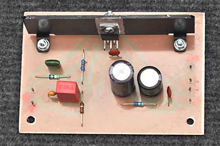
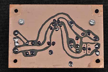
Assembled filter module circuit board
The above photo shows the filter module. As the circuit isn't overly complex I used a piece of 100mm by 70mm laminate, giving plenty of room to lay out the board without cramping things up too much; as I draw my tracks manually this means I don't have to draw very thin tracks. (I enjoy doing this manually, as if I need to give a reason.)
The Output Stage
The output from the filter board passes into a conventional TDA2003 chip amp which provides around 40dB of voltage gain (X 100), a fair chunk of the gain this receiver provides, and enough power to drive a loudspeaker. I believe this chip is now obsolete, but may still be available as new old stock. For an output of just under 1 watt, you could use an LM386 instead and if I was starting from scratch, this is what I would now use.
Output stage circuit diagram
The above diagram shows the circuit for the output stage, based around the TDA2003. There are plenty of diagrams for this available on the Internet, most, like this, based heavily on the one published in the data sheet.
OUTPUT STAGE CIRCUIT DESCRIPTION:
This is the classic circuit suggested in the data sheet for the TDA2003 audio output chip, with a few minor modifications. The input capacitor is now a non-polarised 1µF ceramic capacitor rather than the (unnecessarily large) 10µF capacitor suggested. This low value does reduce low frequency response somewhat, but this is of no consequence in this application.
The feedback capacitor is shown as a 10µF film capacitor rather than the 470µF electrolytic capacitor suggested. This much smaller value of capacitance causes the low frequencies to begin rolling off from around 100Hz, but this is fine for this application. In addition to this, there is less than a volt of bias across this capacitor so a conventional electrolytic may eventually become a bit leaky in this position, and leaks aren't good in a feedback path. (The 1000µF speaker coupling capacitor could be reduced greatly in value too, and although untested, a 220 µF or even a 100µF capacitor would probably be fine with an 8Ω load.)
Finally, the high frequency roll-off is controlled by the 0·047µF capacitor and the 39Ω resistor. The capacitor is slightly larger than the 0·039µF shown on the data sheet as I happened to have that value available. With this slightly larger value, the high frequencies now begin gently rolling off above around 13KHz, which again is fine for this application.
Output board top |
Output board bottom |
The above pair of photos show the output board I threw together. As can be seen, it is a very simple circuit with the minimum of components which I spread out over a piece of 100mm by 70mm laminate, as I have several pieces of that size and I didn't want to be bothered cutting any. The heatsink may seem marginal, but as this amplifier draws less than 50mA when idle, the heatsink remains completely cold under normal conditions. Even under test when supplying 2 watts of continuous power into an 8Ω load the heatsink only became slightly warm.
A quirk of the TDA2003 is that the output seems to need to pass around 30mA of current continuously via the 220Ω resistor to ground to keep it stable, which also forces the output stage to operate in class A mode for low level signals, presumably to keep crossover distortion at an acceptable level. This current wastage isn't a problem for in-car use as was intended by the designers, but may become an annoyance when running off a battery.
Attempts at increasing the values of the 220Ω and the 2·2Ω resistors while keeping the ratios the same simply resulted in severe oscillation, so further tests along those lines were abandoned. I see this as a basic flaw in the design of the chip but one I can live with, especially as there don't seem to be any other true single-rail amplifier chips out there with this power output.
So in summary, we now have an output stage adding a potential 40dB of gain to the total at full volume, with a frequency response which starts to roll off above around 13KHz, pretty much ideal for this application; heck, I can barely hear 9KHz these days anyway!
That reminds me...
Fairly recently both me and a mate became slightly concerned about the lack of grasshoppers. We used to hear these things chirping away on summer evenings, but these days, nothing at all. The consensus of opinion was that insecticides must have killed most of them off, until one evening when out on a walk by the coast with my wife, she happened to mention the vast numbers of chirping grasshoppers she could hear and yet all I could hear was the gentle sound of a breeze blowing through some marram grass. Slowly the penny dropped, and I realised that at my age I could no longer hear frequencies that high; the revelation was a little upsetting at first, but apparently this is normal for males of my age so I have no choice but to accept it.
The Completed Unit
The various modules were mounted on the back of an aluminium panel in a very amateurish way, which fits onto the front of a reclaimed steel enclosure. Some additional bits of circuitry were tacked on over the years, these being made in the classic bird's nest' style for simplicity and to allow easy changing of component values should it become necessary, the whole unit being the result of many years of gradual evolution.
The speaker is one which has a mylar diaphragm; this was originally chosen by chance but has proved to be ideal due to it being splash resistant, and the frequency response is well suited to this job, having a poor low frequency response but a good response at good efficiency well into the treble range.
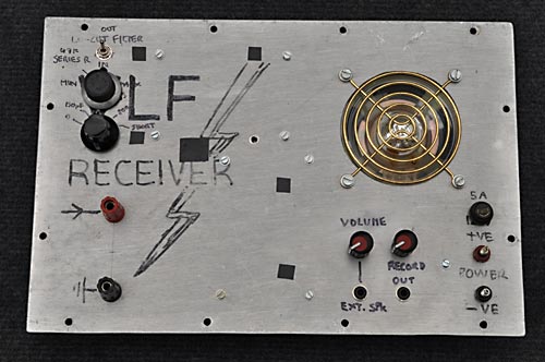
Front panel controls |
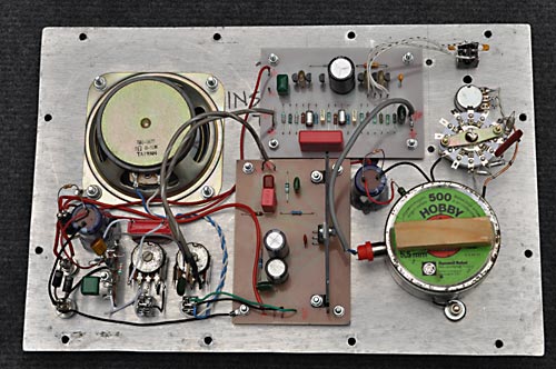
Rear of front panel |
The whole receiver could, of course have been made a lot smaller than this, but this was the box I had available so I used it; any box would probably need to be made of metal for stability, but there's no particular harm in trying a plastic enclosure to see what happens, but above all, don't worry what it looks like, it's all experimental fun after all. 😎
The Practical Side Of Setting Up A Receiver
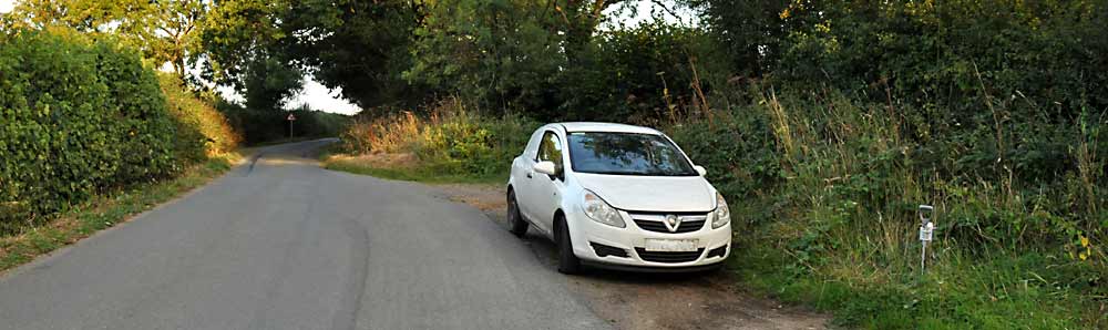
My favourite spot, 5 minutes from home. Note the fork stuck in the ground with the antenna fitted.
Theory and circuit diagrams are all very well, but some practical advice on how to set up the VLF receiving equipment may be helpful.
YOU'll NEED A RECEIVER
Of course you will, and at this point I assume you've equipped yourself with something suitable, and a suitable power source; you may not be able to use the car's battery: see further down.
FIND A GOOD LOCATION
The most important thing to sort out is where you are going to set up. 11KV power lines radiate an intense electrostatic field for some distance around them, so you need to find somewhere as far away from them as possible as otherwise this will just swamp your radio with 50Hz hum, obliterating the far weaker natural signals. Given that much of the UK has houses scattered around the place, for best results you'd need to find somewhere remote; here in the South West I can go to Dartmoor, where some regions are sufficiently far away from those dastardly power lines to allow decent reception.
I've also recently found a good spot up on the Blackdown Hills, where the power lines are at least 3 large fields away in every direction, meaning the level of mains hum is sort-of acceptable considering the location is 5 minutes from my house, a reasonable compromise. Forget trying to listen in any built-up area, it'll be a waste of your time; I doubt even dedicated filtering software would be able to clean up that mess.
INTERFERENCE FROM YOUR CAR
During a recent resurgence in my interest in VLF, I stuck a CB antenna onto a magnetic mount on the car roof, as I had done before. I was somewhat irritated to find that modern cars (even something as old as my Corsa) radiate interference themselves when parked up even with the key out, which was inconvenient to say the least. Locating the antenna away from the car reduced the intensity of the interference a small amount, but the only effective remedy was to disconnect the bloomin' car battery which I now do, and have got the procedure down to 30 seconds or so.
THE ANTENNA
You'll need an antenna of some kind; it doesn't have to be anything fancy and could even be just a couple of metres of wire suspended from a branch or similar. This isn't a resonant tuned antenna; it's more like an electrostatic probe up in the air, and the longer the antenna, the stronger the signals but be aware that longer antennas also receive stronger interfering signals; I've found that around 2 - 3 metres is plenty. You should also poke an earth stake into the ground and connect that to the ground terminal; I do this as a matter of course as it makes the whole unit more electrically stable.
Antenna bracket fitted to the fork handle
I found (borrowed from my wife - permanently) a garden fork, and mounted a CB antenna bracket onto the handle to allow an 8-foot antenna to be fitted. The fork can be pushed into the ground as you do with forks, and the aerial connected to the receiver. An earth wire is also fitted, with one end clipped to the metal part of the fork, and the other end earthing the receiver. Siting the antenna near trees will reduce the signal strength somewhat, but if your receiver is sensitive enough, it may not be an issue; just something to bear in mind when choosing a location especially if your receiver's sensitivity is marginal.
THE FEEDLINE
The signals from the antenna/earth system obviously need to be connected to the receiver, and the wires responsible for this are known collectively as the feedline. You could use coaxial cable for the antenna feed but the relatively high capacitance of around 100pF per metre for this type of cable will shunt a fair bit of the signal, possibly leading to disappointing results. I decided to make some ladder line for the feedline, and with its very low capacitance between the conductors, it transfers those high impedance signals efficiently.
Making some spreaders |
Home-made ladder line |
A length of ladder line isn't too difficult to make; I used some cable ties cut into 50mm lengths, and then carefully drilled a 2·5mm hole in each end. This happened to be just the right size for me to thread the spreaders onto the wires, the fit being tight enough that the spreaders didn't need fixing in place. Of course, the hole size you'd need depends on the wire you plan to use, and a dab of silicone rubber would secure the spreaders if necessary. The spreaders were spaced at around 100mm intervals, but this is by no means critical; just use enough to support and spread the wires.
The length of ladder line is then run from the antenna and fork assembly, passing over grass and brambles, in through the car window and into the receiver. Due to the very high input impedance of my receiver, it was interesting to find that just rubbing the 'live' conductor with my finger produced a rubbing sound in the speaker; it's a very sensitive piece of equipment!
Notes:
It is worth mentioning that I now drive a separate earth stake into the ground beside the car door, and earth the car body (via the seat mounting bracket) and the case of the receiver, linking all 3 points. This for some unfathomable reason reduces the level of mains hum.
MAKING RECORDINGS
To record the received signals I use an oldish laptop running Windows 7 and Sound Forge 6.0; older laptops sometimes use the cold-cathode type of screen illumination which creates a lot of hash, but this one uses LED illumination which is a lot quieter electrically. I discovered that having a USB mouse plugged in (I dislike those touch pads) caused noise to be radiated so that was removed, forcing me to use the darned touch pad.
My isolation transformer lash-up
As a final exercise in noise reduction, I fitted a 600Ω : 600Ω audio isolating transformer I'd scrounged from a computer internal modem card between the receiver's record output and the laptop's input which helped isolate more laptop interference.
Ultimately you may not need all of these measures, but this gives you an idea of things to try if you experience interference problems.
What Can Be Received?
If the equipment is working correctly, the first thing you should hear is a crackling sound, the atmospherics, the sound of a living planet; this sound forms a permanent backdrop to the VLF spectrum in which other sounds may be detected. These crackling sounds are caused by lightning strikes around the globe, presumably the louder ones being closer in origin. The sound of the crackles range from a low popping through normal-sounding crackling to higher-pitched almost squelchy sounding components, which together cover the entire audio range.
All my sound clips have been rendered in ogg format which is supported by all the major browsers; quite why people are fixated on the inferior mp3 format I don't know, maybe it's the result of aggressive marketing back in the day when a licence fee was payable? In any case, mp3 performs poorly on transients, which these recordings consist almost entirely of; ogg format performs considerably better for a given file size, and is good ol' open source too, so there.
54 seconds of atmospherics
This is a 54 second recording of the usual VLF background noise which is always present to some degree, although some days are more active than others, this one being one of the more active.
75 seconds of lightly 'tweeky' atmospherics
This 75 second capture was recorded at dusk in September 2025 and if you listen carefully, some tweeks are starting to become noticeable among the normal noise, making their characteristic 'pew pew' sound.
A pair of passing cars
If you are parked beside a road on a dry day, every time a car passes you will most likely receive the sound of the static electricity built up on the car's tyres. Not particularly interesting, but it does illustrate how sensitive this equipment is.
Insects flying close to the antenna
Here is the sound of a couple of insects flying past the antenna, the static on their wings making them audible in the receiver. This tends to occur mainly during warm days when the insects are more active, and while not related to VLF, a nice example of a fly-by is worth recording in my opinion; I'm still waiting for the perfect capture.
3 quiet whistlers
This 13 second recording features three quiet whistlers: don't blink or you'll miss them; the middle one is barely audible, but is there between 5 & 6 seconds in. On this occasion conditions were very quiet, but occasionally whistlers like this could be detected down in the noise. The gain has been increased a fair bit to allow the whistlers to be easily heard over computer speakers.
As of 2026 I plan to add a lot more recordings to this section; I'm just waiting for the right conditions and phenomena to occur. I did record some whistlers recently, but the interference from VLF data transmissions spoilt the recording; I've now resolved that issue with more aggressive filtering.