Introduction To The Project
OK, maybe constructing an efficient 80m antenna on a real postage stamp may be a tad difficult, but the garden of a previous property seemed almost as small especially when contemplating HF antennas.
The challenge I had was to erect the most efficient antenna I could for 80m use within the confines of my back garden, and here I document how I did it, the problems encountered and their work-arounds. This page is primarily for the benefit of anyone out there in radio land who fancies having a go at this but perhaps isn't too familiar with antenna theory and who perhaps lacks practical experience in this type of thing.
Planning The Antenna
Rough sketch of the planned 80m ¼ wave antenna layout
Before I could start hanging wire in the air, I had to plan roughly how the antenna was to be laid out and how the heck I was going to get such an antenna into my garden, as a quarter wave length of wire at 3.7MHz amounts to almost 20 metres depending on the proximity of the ground and other objects. Calculating the length of an antenna is not an exact science as some may like to tell you as there can be a fair bit of trial and terror involved, and a fair amount of wire shortening followed by wire lengthening, accompanied by gnashing of teeth and sweat. However, going for a quarter of the electrical wavelength should ensure you have too much wire ready for some trimming.
The first thing was to determine the anchorage points and where the feed point was to be situated. As this antenna was to be of the inverted L design, I wanted to get the feed point at the far end of the garden, well away from the house. This minimises the chances of RF fields affecting stuff in the house, and makes the antenna less likely to pick up rubbish from similarly located dodgy electrical items. The basic idea was to have a vertical element at the far end of the garden and the horizontal bit coming back towards the chimney. I already had a vertical antenna for 40m with crappy but workable ground radials so I decided to simply plug the new antenna into the same feed point; yes, common feed points do work, especially if the frequencies are reasonably far removed as in this case.
Back to top
Laying Down A Radial Field
If you don't already have a radial field laid down you are going have to make one. Make a mounting point insulated from the ground to which you will eventually connect your antenna, and a common connecting point for the radials. I happened to have the mountings for a well pump available so welded up a short bracket to fit on this to allow the mounting bracket from an old CB antenna to be fitted. The best advice with radials is to lay down as many wires as reasonable, making each as long as you can whilst keeping them fairly straight. I have 8 radials in total, covering about 180 degrees. Many will tell you this is woefully inadequate and so it may be, but with a small garden we have to accept some compromises, right? I was able to sweet-talk one of my neighbours to allow me to bury radials diagonally across their lawn so this helped a lot - maybe you could ask yours? What is the worst they can do apart from putting drawing pins in your co-ax?
Any radials should be buried an inch or so below the surface of any grass to protect them from lawn mowers, children and the like, but any others will have to be laid on the surface. I used insulated multi-strand wire, and sealed the far end with a blob of silicone rubber sealant to stop water wicking up inside and causing corrosion. If you can get your hands on solid bare copper wire then this might be better, certainly as far as a DC earth is concerned. The photo below shows the feed point of my 40m vertical, mounting bracket and the copper ring to which I soldered my radials. The 80m inverted L feedpoint will be attached to the hose clip visible at the base of the 40m vertical element. Don't look too closely at the welding; It may not look pretty but it has been thoroughly tested with a big hammer and I blame it on the welding equipment anyway.
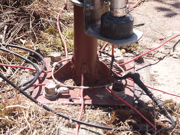
Showing where my radials are connected together
Setting Up The Antenna
The vertical part comprises a 9 metre roach pole fixed to the side of the shed as illustrated below; the backward lean of the bracket was intentional and not a result of too much alcohol in the bloodstream. The reason for the lean is that it compensated somewhat for the bending of the roach pole once the top section was attached. Using a pole like this is a useful approach as you immediately take up 9m of the antenna's length, and you haven't strung anything up yet! Some 2mm diameter enamelled copper wire was wound in a stretched helix up the pole - this was simply to ensure the wire stayed with the pole and didn't flap about in the wind. No tight coils here, just maybe one turn per metre or so is all that is needed to secure the wire. I suppose you could also tape the wire to the pole if you wanted to. The top of this type of pole is very thin and will eventually be pulled over into an almost horizontal position by the horizontal part of the antenna, so leave a bit of the wire protruding an inch or so beyond the tip of the pole to enable the horizontal wire to be soldered to it. Use duct tape or similar to secure the wire to the very tip of the roach pole.
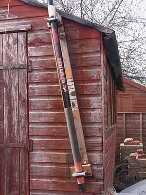
Roach pole fitted to the shed angled backwards to counter bending
You now need to devise an anchorage point at the house end, and for this I had to engage the services of the local TV antenna installation guys to come out and fit a pole to my chimney, as there was absolutely no way that I was going to be persuaded to climb up there myself. OK, it costs, but I think it's worth it. The sneaky bit (And the bit I'm quite proud of) is that I made up a fitting using an exhaust clamp and a pulley which the guys fitted to the top of the antenna pole for me, and through which they passed a thin rope before they left.
Having access to a string on the ground would enable me to raise or lower the antenna as I wished washing line fashion, making it a simple matter to make adjustments to the antenna.
Back to top
Radiation Resistance, SWR And How I Improved Things
The original intention was to adjust the total length of the antenna to resonate on or around 3·700MHz, and I did run the antenna like this for some time. The main issue was that even at resonance the system was showing an SWR of about 2:1 which is less than ideal, so I had to use the shack matching unit to show the radio a decent match, having to make adjustments each time I changed frequency more than a few tens of kilohertz. This frequent re-tuning was a real pain particularly during the RSGB Club Championship phone contests in which I was a keen but inept contender.
Having since analysed the situation by taking readings and referring to antenna design software it has became apparent that the antenna system was presenting a load of about 24 ohms at resonance, made up of about 12 ohms radiation resistance and an estimated 12 ohms in earth losses; the low value of radiation resistance is normal and due to the antenna's relative proximity to the ground. This was not really a good situation as around 50 percent of whatever power made it into the antenna was warming the worms, without even allowing for the mismatch. The almost 2:1 SWR would have meant a fair bit of power was being lost in the feed line too, as I only use RG58, although it is the good stuff with a foil layer under the braid.
To add insult to injury, because the high current portion of the antenna was in the vertical section there was little radiation going out at higher angles, which is where I wanted it for my inter-G contacts.
I made it longer! Rough sketch of the new extended 80m antenna
The solution was to simply lengthen the antenna by a few metres as illustrated in the diagram above. I didn't have quite enough span between the roach pole and the chimney for the extra length so I ended up doubling the far end back on itself for a couple of metres, with the last metre or so of wire left dangling downwards. All this extra length puts the antenna way out of tune of course, and in fact the bare element was now resonant on 2·750MHz. So how did this help? What this did was increase the inductive reactance to between 200 and 300 ohms, but also the resistive component was increased somewhat to about 38 ohms at 3·7MHz, being a little lower at lower frequencies and slightly higher at higher frequencies. Still no good for the moment though, as the high inductive reactance would have caused a very high SWR on the feed line.
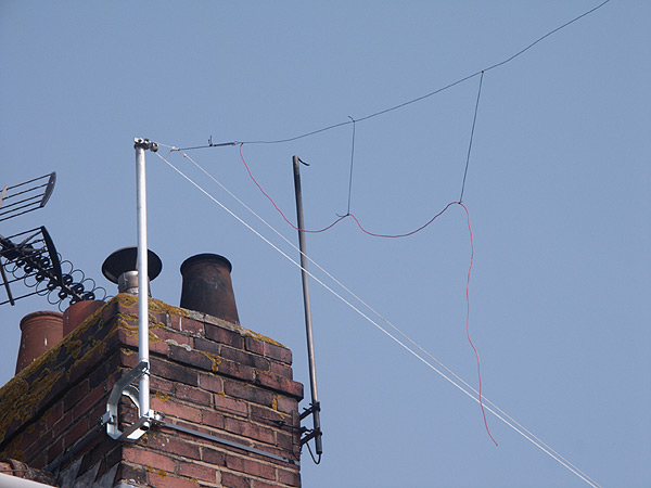
Doubled-back end of the antenna and pulley arrangement
So what do we do?
We place a variable capacitor in series with the antenna element at its base to cancel out the inductance, leaving just the resistive 38 ohm component. By careful adjustment of the variable capacitor I can now get an almost perfect 50 ohm match at any frequency within the 80m allocation. There are still earth losses as the 12 ohms earth resistance is still there, but it now amounts to far less than half the total. The other benefit is having an excellent match to the feed line, meaning I no longer need to use the shack tuner and subsequently no longer suffer appreciable feed line losses. Finally, lengthening the antenna has resulted in pushing the high-current portion of the antenna 'up around the bend' meaning in theory I get better high angle radiation, just what I wanted.
Initially, the variable capacitor was placed in a bucket at the base of the antenna, with a couple of brass studs fitted through the side of the bucket for attaching the feed and antenna connections. The photo below shows the bucket in situ, and the more astute amongst you will notice there are in fact two variable capacitors in there. The one standing on end is the variable element, whilst the other centres the range by padding out the other capacitor and once set, gets no further adjustment.
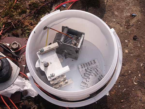
My first tuner for the base of the 80m antenna
This system worked well for a while, but the ritual of running up to the end of the garden to adjust the capacitor every time I wanted to change frequency became a bit of a pain, partly because the capacitor was not calibrated and therefore several trips were needed to correctly set it for minimum SWR, but mainly because I was simply not built for running. This limitation was a particular problem during the RSGB Club Championships SSB contests, and for this all I could realistically do was set to mid-band, and tune out the high SWR using the shack tuner when operating anywhere other than at the tuned frequency; not really making the most of what the antenna was capable of.
Back to top
Remote Control Of The Capacitor
I decided that what was needed was some means of controlling the capacitor from the operating position, and so I developed a means to accomplish this.
I had in mind to make use of a servo unit as used in radio controlled models, and after a few enquiries managed to scrounge one for free to experiment with. Servo units for radio controlled models usually require a 5 volt supply to operate, and a signal on the third wire to tell it how far to turn. This signal takes the form of a short 5 volt pulse repeated roughly 50 times a second, the duration of the pulses 'telling' the servo at what position to turn to and hold at. Varying the duration of the pulses from just under 1mS to just over 2mS (depending on the particular servo used) usually causes the servo unit's shaft to rotate through 180 degrees.
I did a bit of research and ended up using a 555 timer IC to produce the necessary pulse stream for controlling the servo. Initially the circuit was lashed up in a rather amusing way while I finalised the timing components to produce the correct range of pulses for this particular servo unit. Pictured below for your entertainment is the actual birds-nest lash-up I used, and if you look carefully you can see the 5 volt regulator and decoupling capacitors, the 555 IC in an oversized socket and the wire wound potentiometer I had decided to use for this, along with other resistors, diodes and capacitors.
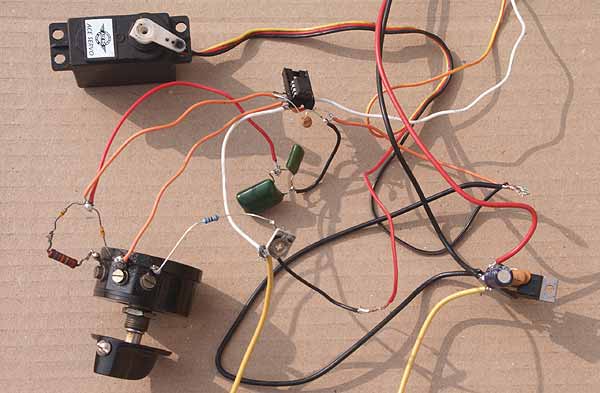
My experimental 80m servo controller circuit
During initial testing it became apparent that I would have no idea whether or not the servo had stuck, or if it was even getting any power so I devised a circuit to light an LED when any significant current was flowing up the cable to the remote servo.
This current indicator has proved very useful as a way of getting confirmation that the servo has become energised, and that it has finalised its position as the LED will now light up red whilst the servo is moving to its new position, and then extinguish when it had come to rest. Once I had settled on all the components I was to use, I etched a circuit board and mounted the bits for the pulse delivery circuit and current monitor circuit. Below is a hastily-scribbled circuit diagram, showing the component values I had eventually settled on.
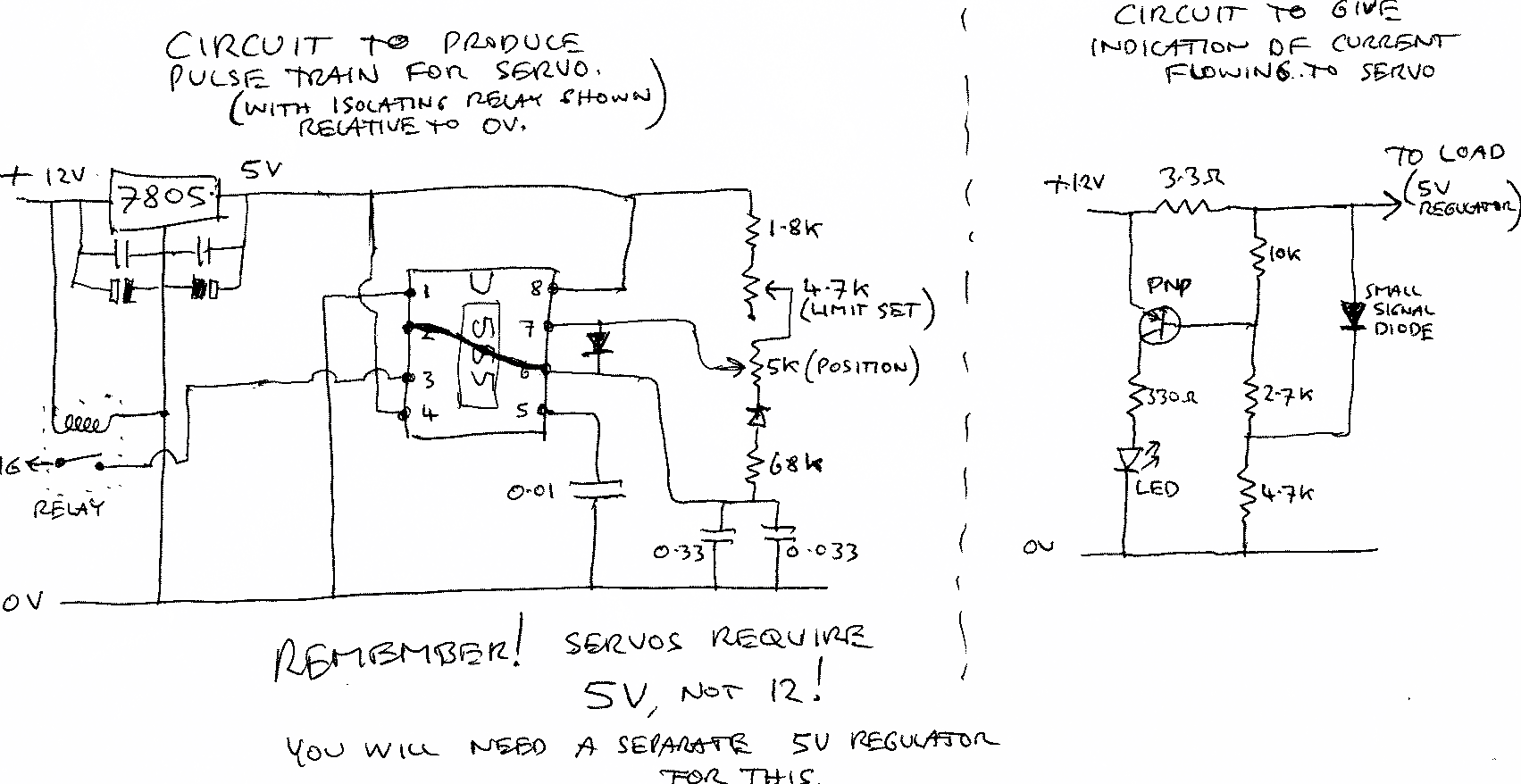
A hastily drawn schematic, for those interested
The picture below shows the innards of the completed servo controller securely housed in an old computer PSU box, and if you look carefully many of the components here are the same ones as were used in the lash-up version I experimented with. The relay was another refinement I incorporated because I discovered that when the power button was released once the servo had moved into position, the servo would then move off position by 5 to 10 degrees, most annoying! The reason for this was the 555 timer circuit continuing to generate pulses as the charge stored in the various electrolytic capacitors fell, but at a slightly altering pulse width, hence the movement of the servo until power ran out altogether. The solution was to simply incorporate a relay to disconnect the servo signal line immediately the power was cut.
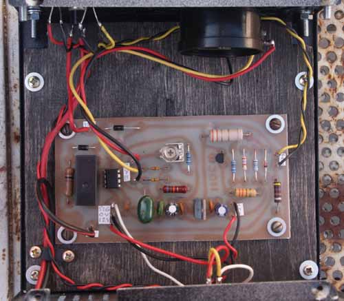
Inside my 80m remote controller unit
The image below just shows the front panel of the controller. You can see the large knob for setting the position of the remote servo, along with the red 'activate' button and a red and green LED. The calibrated scale is intentionally temporary and consists of a piece of paper simply blu-tacked to the front panel. This allows the scale to be easily changed should I decide to make slight changes to the antenna or remote tuning unit.
Operation is quick and simple - you set the knob to the desired position and press the red button for a second or so. The green LED lights to confirm overall power, and the red LED lights only as the servo is moving, going out once it has taken up its new position.
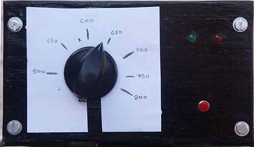
The front of my 80m remote controller unit
Finally, below is a picture of the finished remote tuning unit mounted in its mil-spec all-weather plastic biscuit tin. The same capacitors as were shown earlier in the bucket have been given a more secure home, and the servo unit is now driving the larger of the capacitors using a short section of fuel hose as a flexible coupling. As chance would have it, the capacity range of this particular capacitor enables me to cover the entire 80m band with about 40KHz extra at each end, absolutely perfect. Just goes to show, never throw out ANYTHING, no matter what the wife says!
You can also see a small circuit board which houses another 5 volt regulator which is powering the servo unit, as I'm tossing 12 volts up the cable to this box. Doing this allows for the voltage drop up the 30 metres or so length of cable whilst the servo is operating, as the wire is pretty thin. (It is multi-core audio visual cable.)
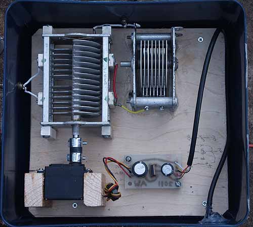
The remote controlled 80m antenna tuner
The system works very well, and much to my surprise can even be tuned whilst applying a carrier of about 50 watts; I did expect the servo to go mad under these conditions with RF being only a couple of inches away but it is very well behaved, the small ferrite ring on the servo's leads no doubt helping with this. It does twitch a bit with BPSK31 or SSB applied, but that is really not a problem as if I have to tune the unit 'live' for calibration purposes, I use a low power unmodulated carrier anyway. The unit is not normally energised during transmissions.