How to build your yagi kit
Assembly Instructions Read Before You Start to Build!
ALL DIMENSIONS SHOWN ARE FREE-SPACE
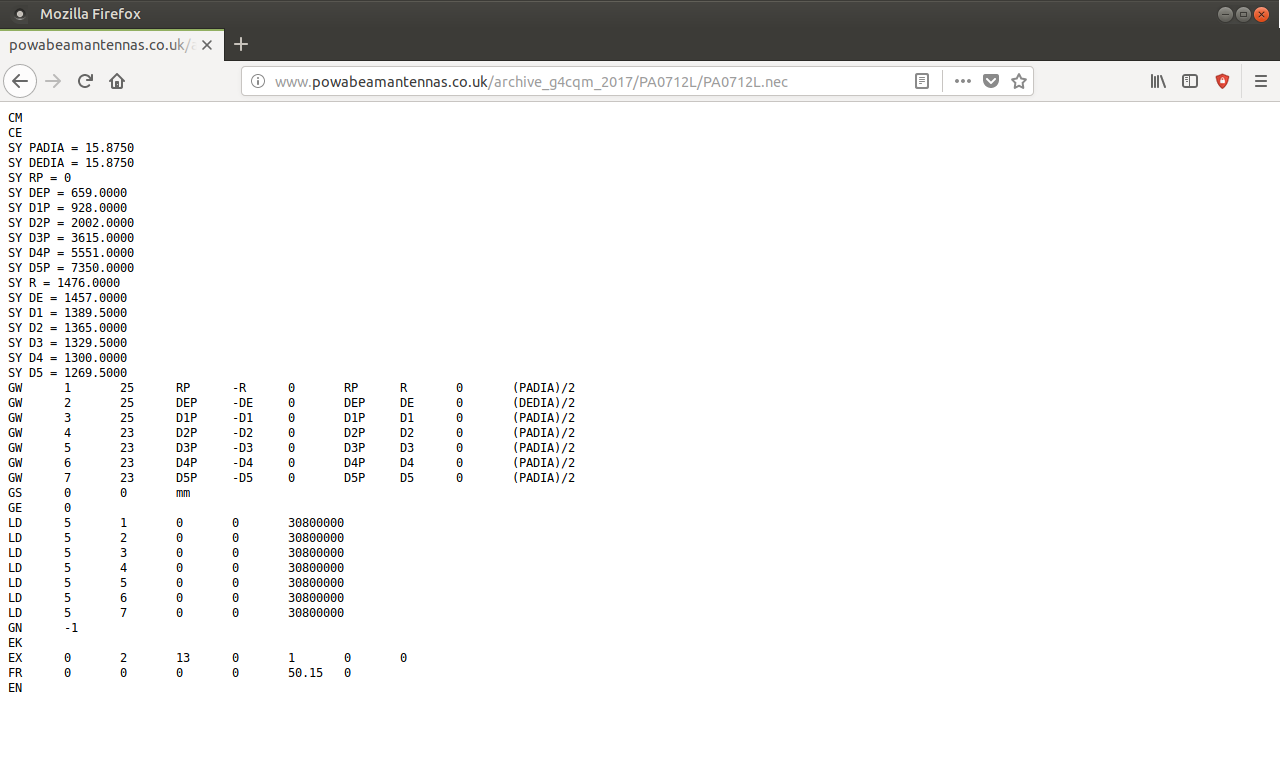
BUILD DIMENSIONS can be found on each of G4CQM's yagi designs pages, look for the YO7 element tables or .ANT file or .nec file (can be opened/viewed in your web browser)! See and click on example below...
| PADIA = Parasitic element diameter |
| DEDIA = Driven element diameter |
| RP, DEP, D1P etc = Element position |
| R, DE, D1 etc = Element length |
Please note that the element lengths shown must be doubled (x2) to give the correct overall length (end to end). Reason, most antenna design software only shows the elements half length.
DO NOT TUNE G4CQM YAGI DESIGNS WITH YOUR VSWR METER ADJUSTING LENGTHS OR ALTERING THE SPACING AND/OR NUMBER OF ELEMENTS... USE ONLY THE EXACT DIMENSIONS SHOWN IN THE ANTENNA FILES!
2M/70CM Element Cutting Tolerances - Yagis have a frequency response that looks very much like that of a Low Pass Filter. Remarkably it is better therefore to cut 1mm too short than 1mm too long. Long elements can result in the cut-off frequency coming into the pass band.
23CM Element Cutting Tolerances - For this band the tolerance is 0.1mm so you will need engineering assistance!
MARK OUT YOUR BOOM PRIOR TO DRILLING USING THE REFLECTOR AS THE START AND POINT OF REFERENCE FOR ALL THE OTHER ELEMENT POSITIONS
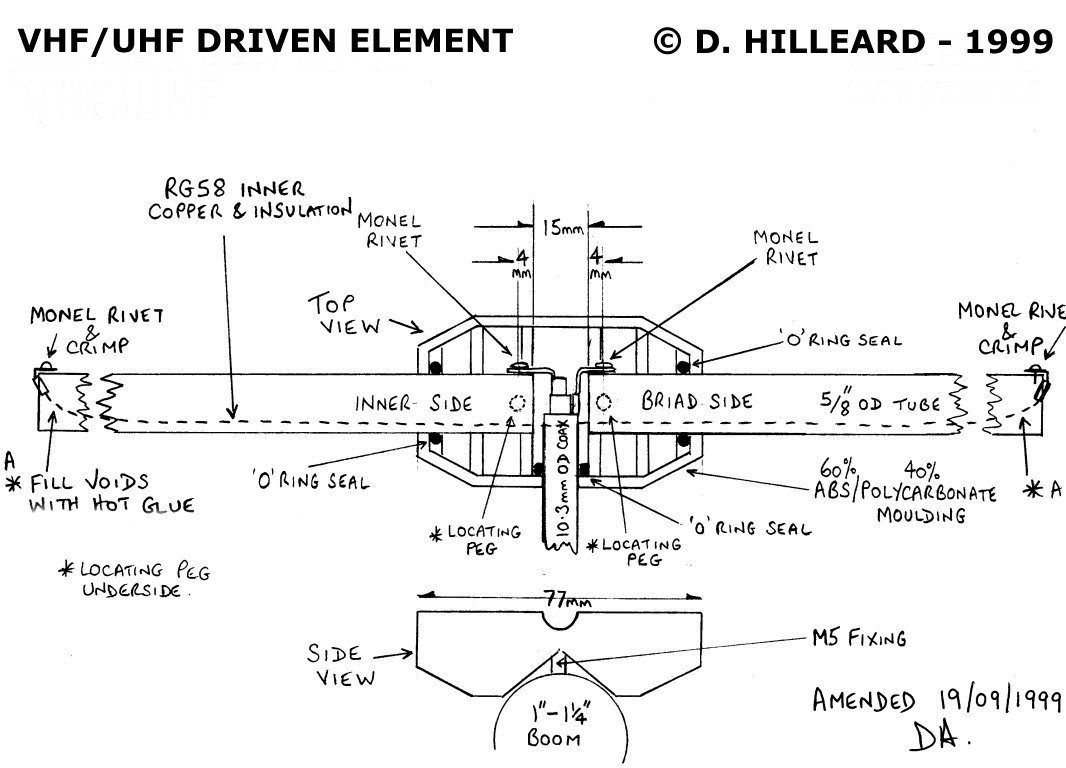
When calculating the driven element length remember that the moulding establishes a center gap of 15mm which forms part of the total end to end length. See working example below...
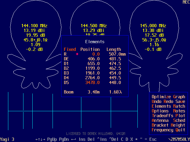
Example 2M7N50LY - From the YO7 elements table above the driven element total length is 481.5mm x 2 = 963mm. To achieve this in practice deduct the center gap dimension of 15mm from the total, and cut a length of tube to 948mm. Finally, cut this into two pieces, each will then be 474mm in length!
PARACLIPS are secured with a single screw/bolt... Recommend M4 Slotted Pan Head Screws (40mm)... Suggest wing nuts for easy portable operating deployment... First insert screw into ParAclip and then locate parasitic element, take to antenna... Make sure that you slightly bevel the edges of the element rod ends so they are not sharp. When you push the elements in from the side of the clip be careful NOT to push the element into your hand, take it slowly. Use a dab of vaseline grease on the element end to act as lubricant, the clip is a VERY TIGHT FIT!... You could for example hold the parasitic element in a bench vice whilst you carry out this process... Finally, some antennas need bracing - a strut/bracket is included but you will need to provide suitable bracing cord/string.
Driven Element Moulding - Assembly Instructions - 05/2012
1. The driven element described here is a 'Coaxial Dipole'. It is formed from two sections of tubing 5/8 inch OD (15.88mm) held in place by the moulding, which establishes a spacing/gap of 15mm. A centre conductor (insulated) passes along inside the dipole and terminates at either end. When DC tested the dipole presents a short circuit. This centre conductor can be formed for example from RG58 inner with the insulation remaining, also tested some PTFE covered surplus cable with exceptional results. The dielectric properties of the insulation need to be VERY good!
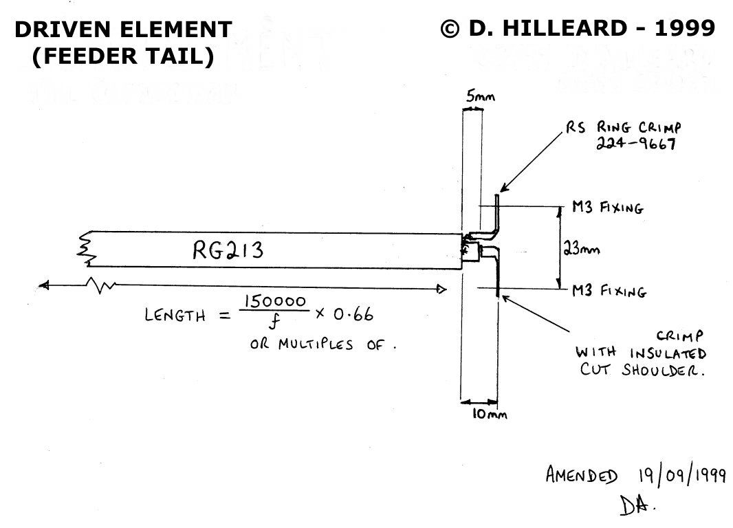
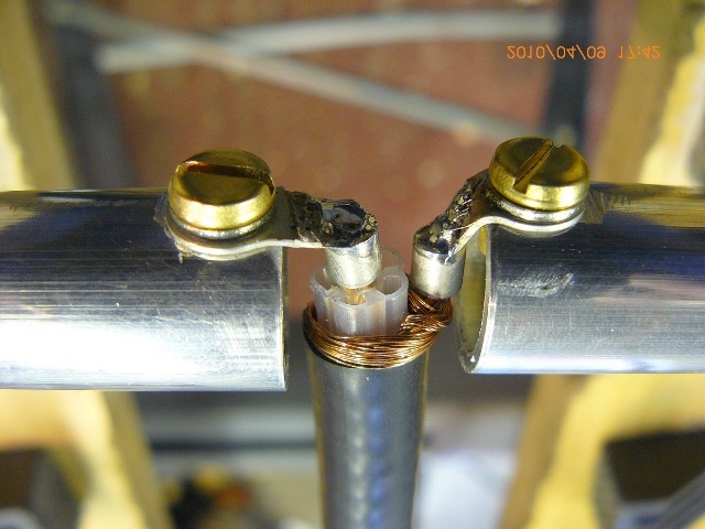
2. Cut and drill the two tube sections of the dipole, there are three holes required in each. One for the locating peg and two others for connection of feeder and centre conductor. Make up the feeder TAIL and centre conductor, Solder on the Tags. The feeder braiding will need to be carefully twisted and inserted into the ring crimp. MAKE SURE THAT THERE ARE NO LOOSE STRANDS OF COPPER AND THEN WRAP PTFE PLUMBERS TAPE AROUND THE EXPOSED FEEDER CABLE/RING CRIMP TO ENSURE COMPLETE ISOLATION PARTICULARLY FROM THE M5 FIXING BOLT BELOW.
WARNING: MARK THE TUBE (EXTERNALLY) THAT IS CONNECTED TO THE COAX INNER SIDE SO YOU WILL BE AWARE OF THE DIPOLE POLARITY FOR STACKING PURPOSES - WHEN STACKING BEAM ANTENNAS USING A POWER SPLITTER TO FEED THEM, ALL OF THE DIPOLES NEED TO HAVE THE SAME POLARITY - FOLLOW THE DE DRAWING - COAX INNER SIDE TO THE LEFT - BRAID SIDE TO THE RIGHT - LOOKING AT THE BASE (HAS M5 BOLT) OF THE MOLDING FROM ABOVE!
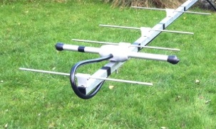
3. Construct the dipole on a flat work surface. A bench vice is ideal for holding each section whilst making the connections with the Brass Nuts/Screws and during insertion of the inner conductor etc. Slide the three 'O' rings over the tubing and feeder cable (one for each), ready for final assembly.
Richard G6HKS shows how to make a neat job of assembly, view looking at the base of moulding...
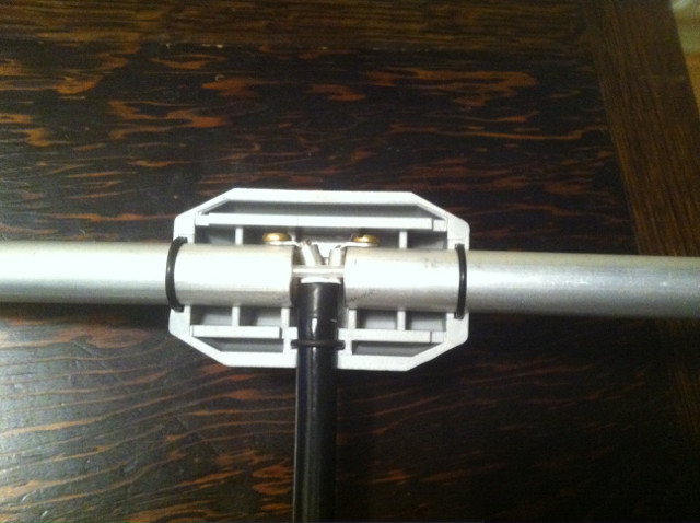
And how to correctly apply silicon / DC4 to ensure no contamination to the bonding surface...
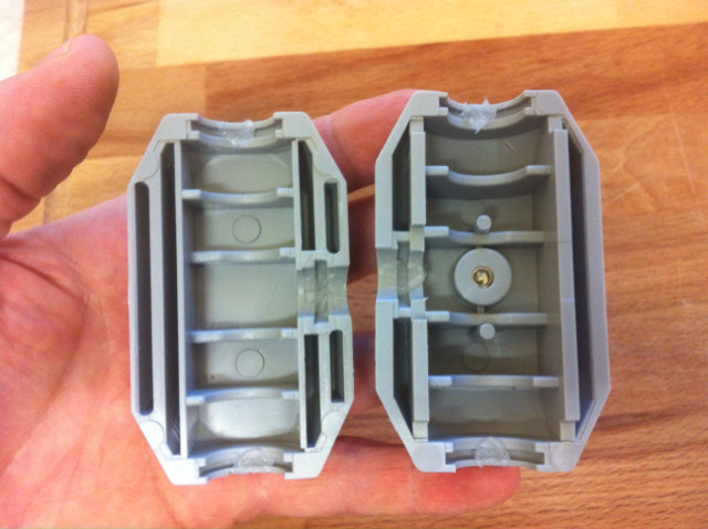
4. The moulding is manufactured from an ABS/Polycarbonate mix and requires a special 'Hard Plastics' adhesive. This can be found in plumbing stores and in the UK sold under the trade name of 'Polypipe'. It is recommended that a jig is constructed which holds the lower part of the moulding. The assembled dipole can then be lowered onto the locating pegs and 'O' ring seals seated in their respective channels. When all the components are assembled into the moulding, adhesive is applied to ALL the facing perimeter areas and tongues.
5. Position lid, the entire assembly MUST then be FIRMLY and EVENLY clamped together. A fast action squeeze clamp is ideal for this purpose. A minimum drying time of 24 hours is required to guarantee maximum bonding strength. The adhesive effectively welds the two halves together.
6. Finally, before sealing the dipole ends liberally spray WD40 silicone free down inside from each end in turn toward the dipole centre. Clean and dry each end, then use a hot glue gun to fill/block each end. When cool, cover ends with UV stabilized vinyl caps. An alternative to this is use our custom uv proof endcaps no need for WD40 this also allows you to cover over the Brass Nut assembly at each dipole end – (G6HKS preferred method)
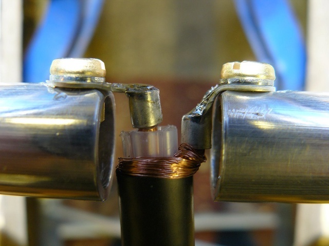
Jerry G4JQN shows how to terminate the feeder/tail (seen before wrapping with PTFE tape and insertion of inner wire) NOTE THE SHORT LEAD LENGTHS REQUIRED AT VHF/UHF FREQUENCIES!
| Click on images to enlarge! | |
|---|---|
 |  |
 |  |
