IN3OTD's web site
...under perpetual construction.

Measurements on magnetic cores
Sometimes one finds some magnetic core in the junkbox, at hamfests or dismantling electronic equipment and wonders if these could be useful for some projects.
Knowing the core material permeability and losses over frequency is of course the first step to understand of those cores can be useful for some RF applications or were intended for other applications.
The theory page describes some methods that can be used to determine the core material characteristics, together with a couple of Qucs simulation examples that can be used to do all the calculations.
These methods were used to characterize some unknown and known cores:
- unknown big bead relative complex permeability and permittivity (dielectric constant)
- unknown toroid relative complex permeability
- Laird 28B0562-300 bead relative complex permeability
Unknown big bead (tube)
Several years ago, my brother found a bag of relatively big ferrite beads at an hamfest. The beads had an inner diameter just right to fit over a RG213 coaxial cable, so seemed ideal to make a W2DU-style common-mode choke. The seller had no data for those and no idea where they came from but the price was good so he bought the whole bag.
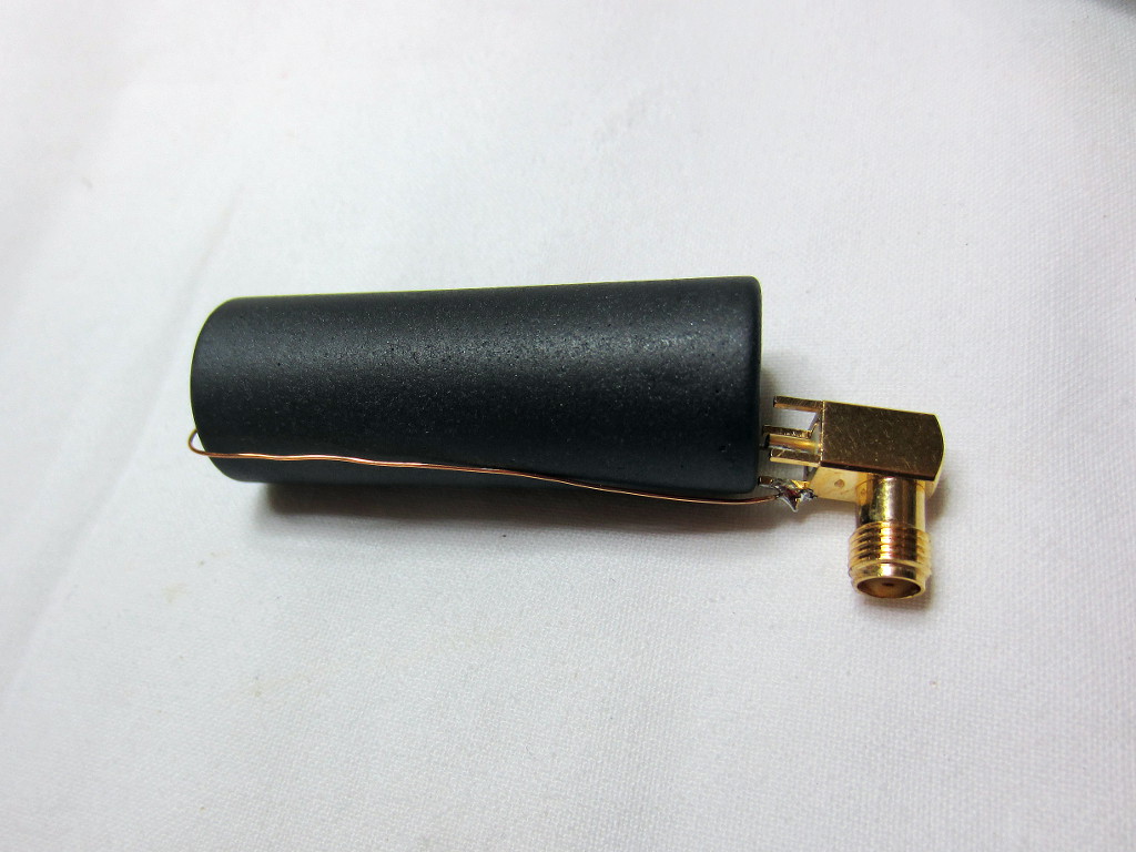
Quite some time later we finally measured the beads ferrite characteristics: the ferrite complex permeability was calculated from the measured impedance of a 1-turn winding:
Here is a graph of \( \mu_{\rm{r}}^{'} \) and \( \mu_{\rm{r}}^{''} \) computed from the single-turn winding impedance:
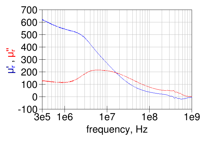
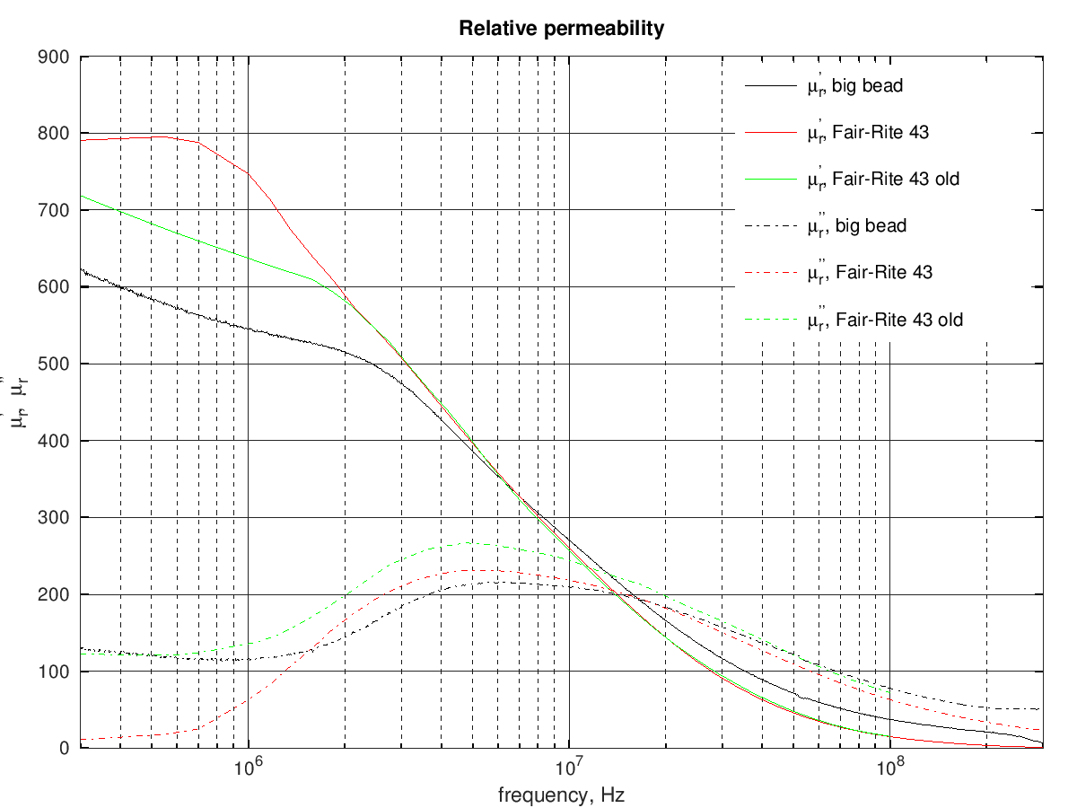
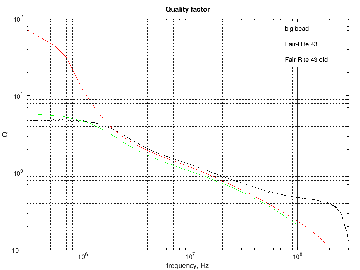
The low-frequency relative permeability is just above 600 and and the material \( Q = \mu_{\rm{r}}^{'} / \mu_{\rm{r}}^{''} \) becomes 1 at around 16 MHz.
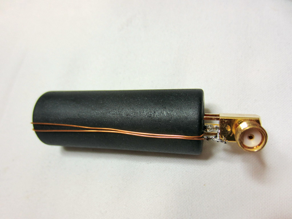
Out of curiosity, the same measurement was repeated using two turns:
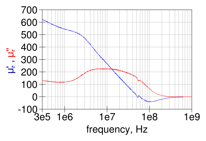
The results are very similar at low frequency, while there is some discrepancy at the higher frequencies probably due to the increased losses and parasitic capacitance in the winding:
After some searching on the internet, the material characteristics seem very similar to the "old" 43 material from Fair-Rite (the current 43 material has a slightly higher permeability and lower losses at low frequency).
Here is a graph comparing the measured relative permeability with a 1-turn winding with the Fair-Rite material 43 (old and new):
Quality factor of the big bead material vs Fair-Rite material 43:
and the permittivity too...
The method described here was used to get the relative permeability and the relative permittivity (dielectric constant) of the big bead ferrite material.
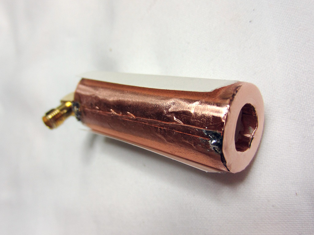
Since the material under test should entirely fill the inside of the transmission line the only practical solution is to build a coaxial structure around the bead. The easiest way is to use some copper tape and wrap it around the outside the bead and, similarly, cover the inside of the bead with another piece of copper tape. A bit tricky to do, put it can be done, with some patience.
The end result is this:

the transition between the SMA connector and the coaxial line formed by the copper foils is far from ideal but is not expected to alter the results much at the relatively low frequencies of interest.
Here is a view from the other end:

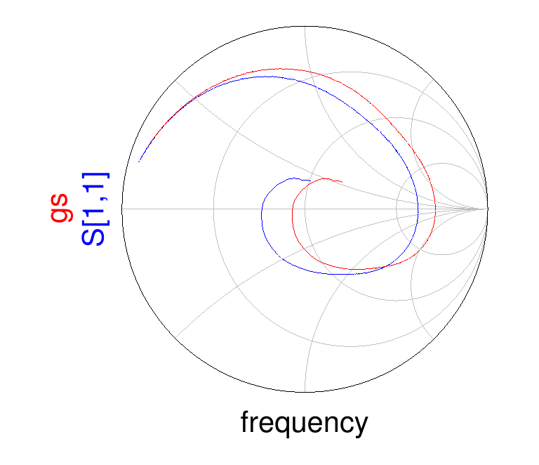
The measured S-parameters for this open transmission line using the material under test as dielectric are shown below: the blue line is the reflection coefficient as measured by the VNA (so referenced to 50 Ω) and the red line is the same reflection coefficient but using the impedance of the coaxial structure without the material under test as reference (about 35 Ω in this case).
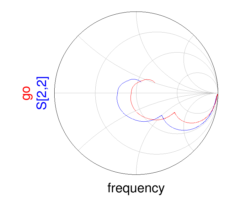
as expected, the open line impedance starts from a very high value at low frequencies and then decreases at higher frequencies, due to the material losses.
After having measured the S-parameters of the open transmission line, the line end was shorted with an annular ring cut out from copper foil:
the annular ring was later soldered to both the inner and outer copper surfaces to ensure a good connection and the shorted transmission line S-parameters were measured.
S for the previous graph, the blue line is the reflection coefficient as measured by the VNA and the red line is the same reflection coefficient but referenced to the bare coaxial structure impedance.
From the measured open- and short-circuited line impedance, the reflection coefficient of an infinitely long coaxial line filled with the material under test can be calculated:
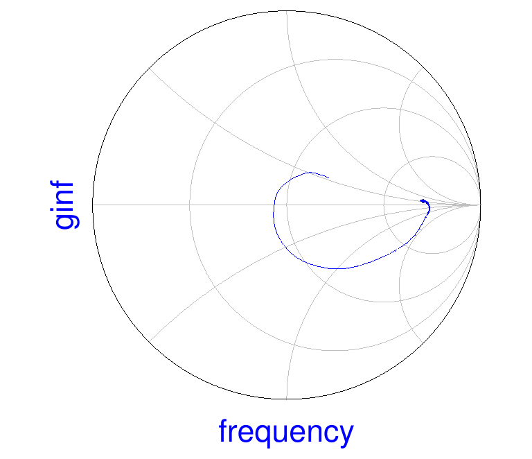
the reflection coefficient indicates a high and real impedance at low frequency, expected due to the high permeability and low losses, which decreases to a lower value as the frequency is increased.
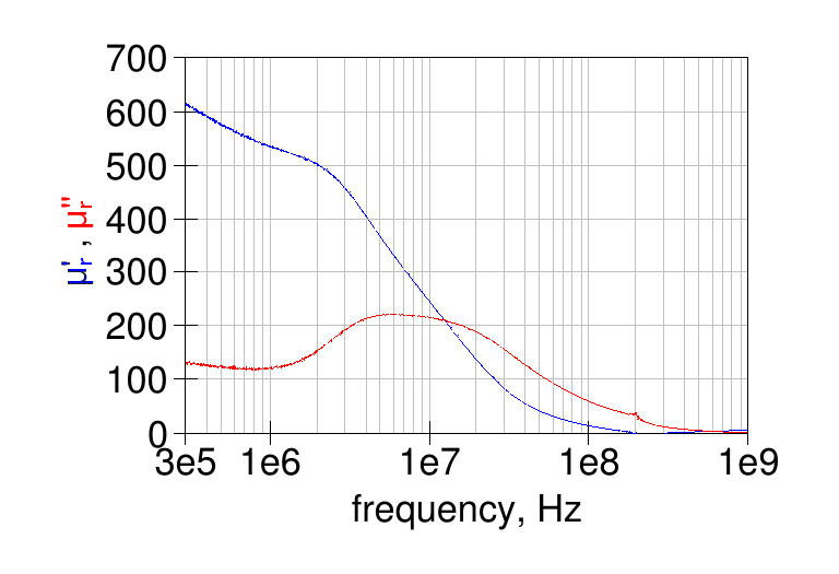
Here is the material relative permeability computed from the open- and short-circuited filled line impedance. The values above 200 MHz are not accurate due to the algorithms limitations:
and here is the computed relative permittivity (dielectric constant):

note that the real part of the permittivity has values similar to the typical values for NiZn ferrites mentioned in [1].
Here is a comparison of the relative permeability measured using the 1-turn method and the open/short transmission line method:

the two methods give quite similar results for the losses, while the permeability provided by the 1-turn method is about 10 higher than the open/short transmission line method.
The following graph shows the quality factor computed from the two methods:
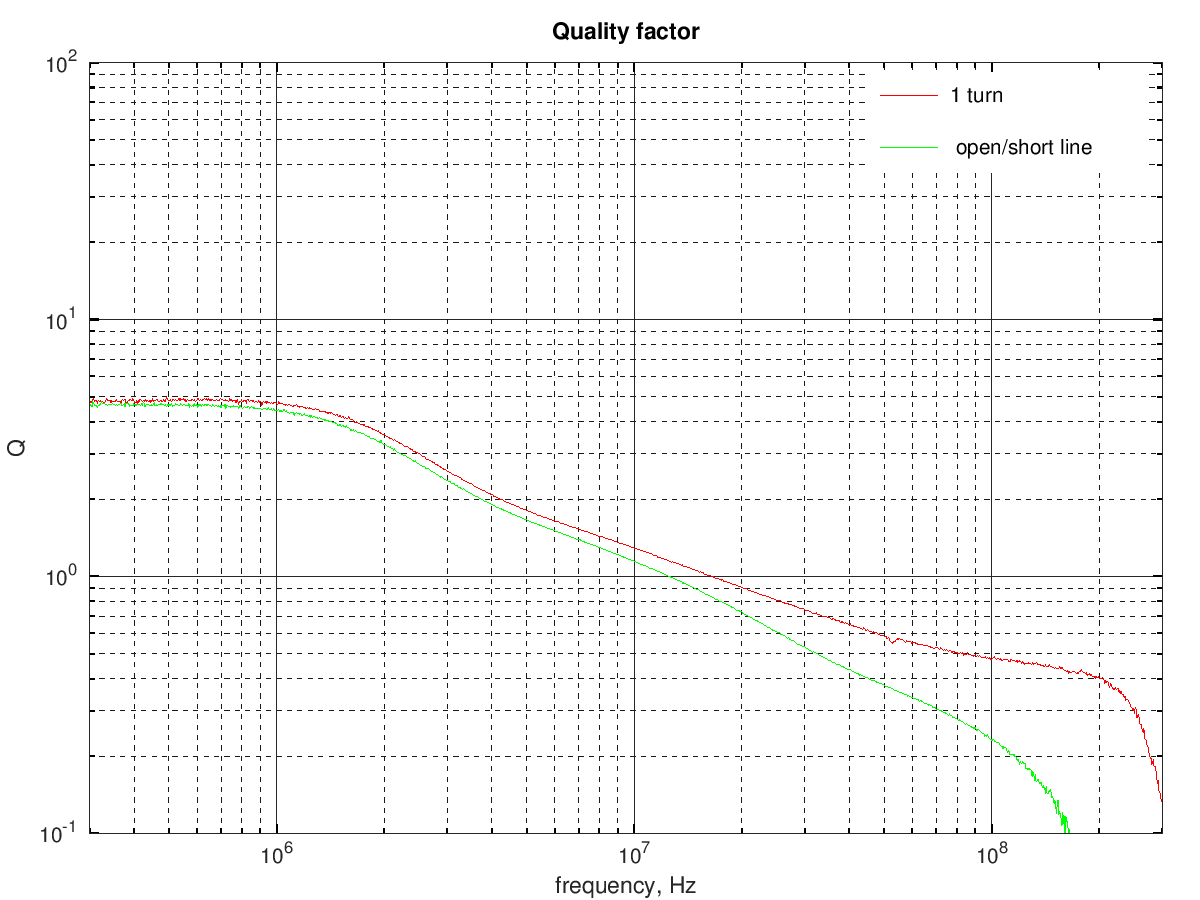
the results are similar until about 10 MHz.
Unknown toroid
I don't remember where this big toroid comes from; I think this too was bought for cheap at some hamfest.
To obtain the ferrite characteristics, first a single turn was wound and the resulting impedance measured with a VNA:

and the resulting permeability is shown in the following graph:

Also a two-turns winding was tried:
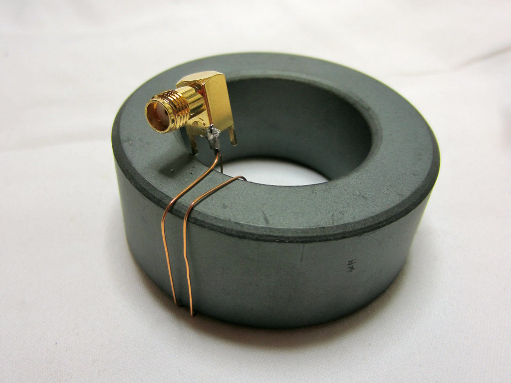
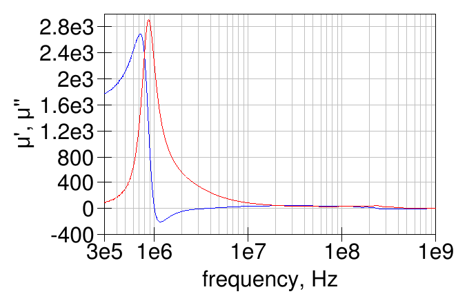
which gave this graph for the ferrite permeability:
The measurements with one and two turns gave quite similar results:
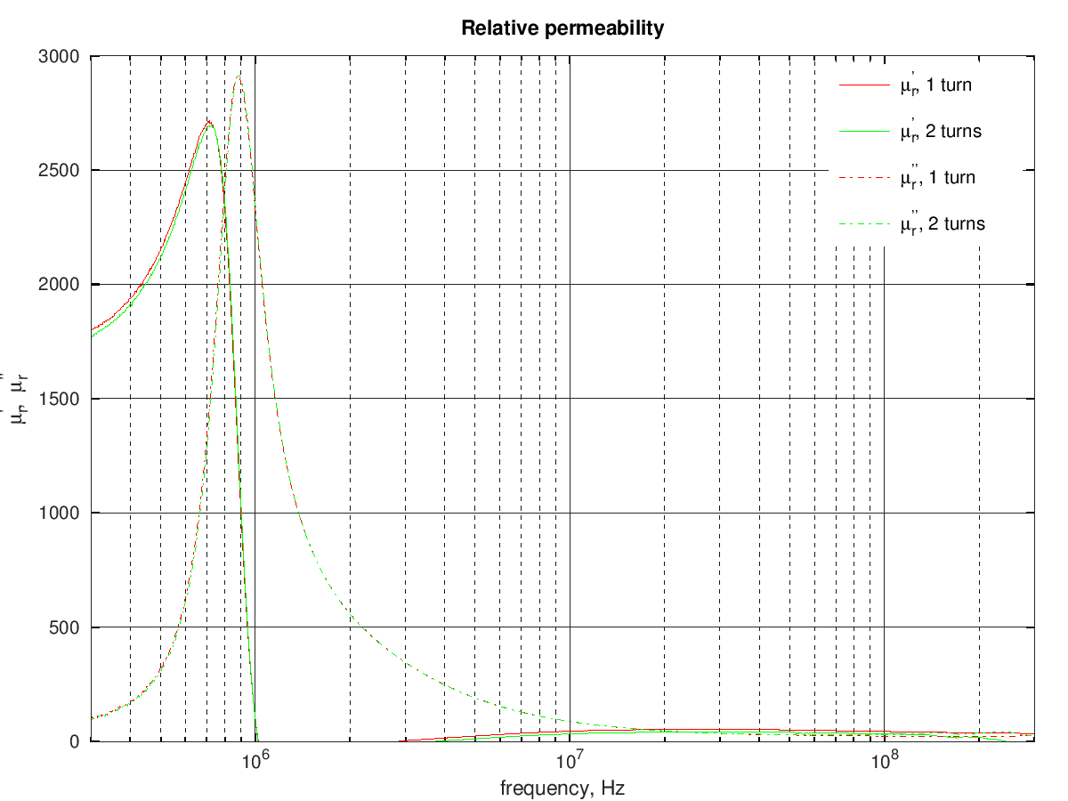
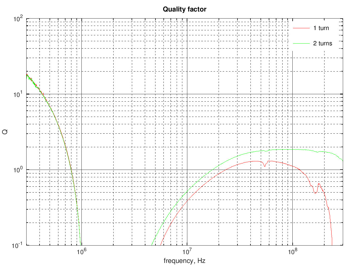
This ferrite material is not suited for HF applications and likely would be more useful for some power applications at lower frequencies.
Laird 28B0562-300 bead
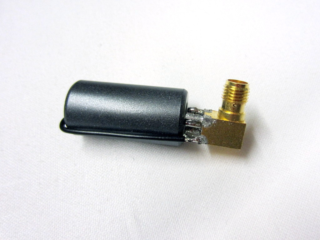
I've seen that some ham-radio HF power amplifier use transformers made with Laird bead, ferrite "material 28". The Laird datasheet does not give much information about the material 28 characteristics, so I measured a medium-sized bead, a 28B0562-300 bead.
The impedance of a 1-turn winding was measured with a VNA:
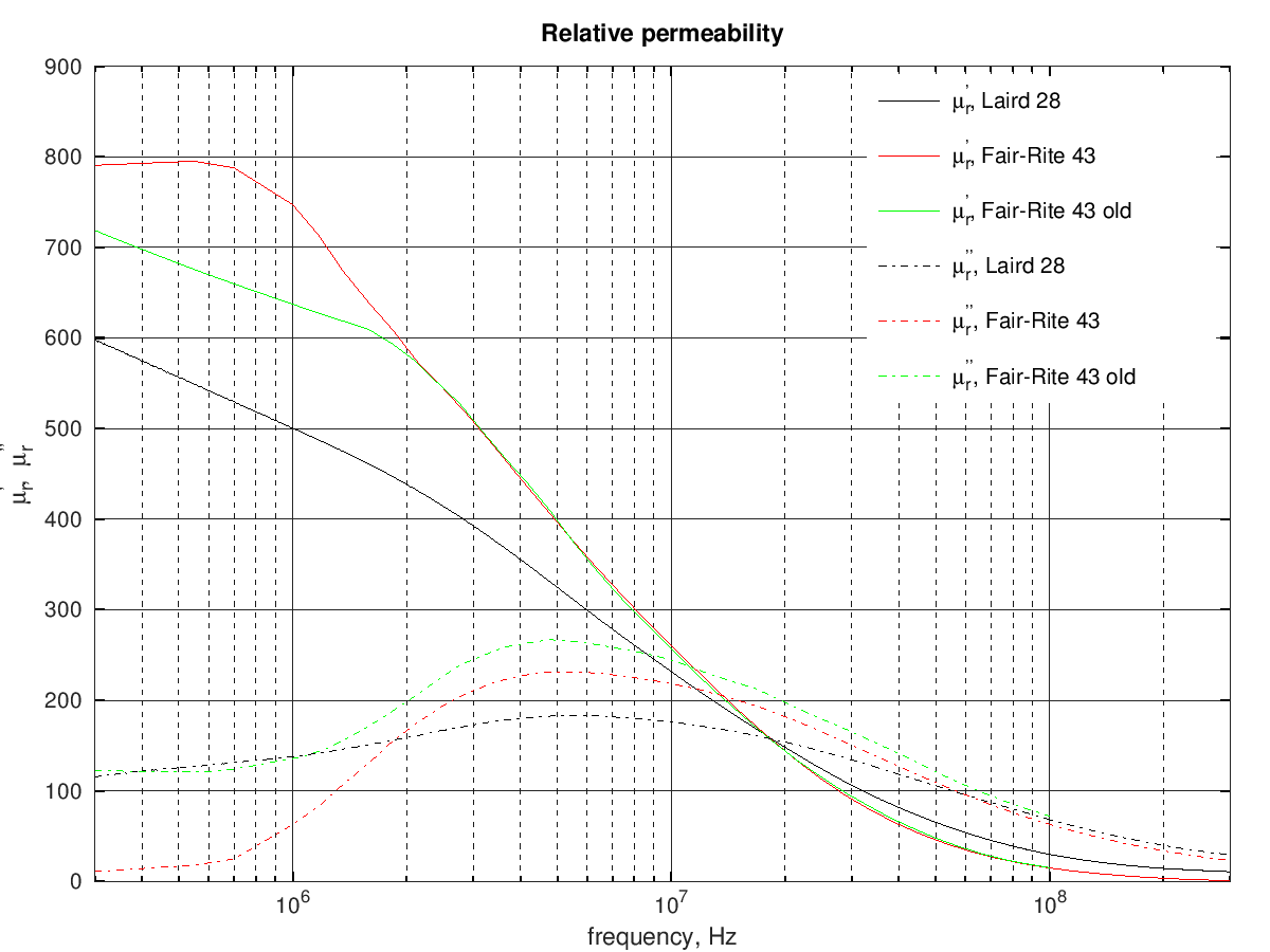
the following graph shows the resulting complex permeability, compared with the permeability of the current and old 43 materials from Fair-Rite:
and here is a comparison of the material quality factor:
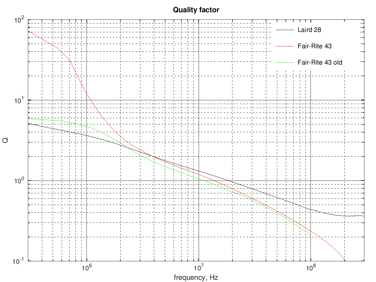
In summary the Laird 28 material looks vaguely similar to the old 43 material from Fair-Rite, with lower permeability and losses at low frequency and could probably be similarly used to build some PA transformer.
References:
| [1] | Ferroxcube, "Soft Ferrites, Ferrite materials survey," (online). |