IN3OTD's web site
...under perpetual construction.

Hermes-Lite v2 beta 2 measurements
Measurement on the Hermes-Lite v2 beta 2 SDR.
Main sections:
RX measurements
Note that the measured noise floor is likely dependent on the actual setup, environmental noise, power supply, board shielding (or lack of), etc., so it should be taken just as a general indication. The noise (and signal) power was measured using the routines from Quisk, which implements a precise "true-RMS" S-meter function.Unless otherwise noted, the audio filter used had a bandwidth of 500 Hz and was centered at 1 kHz.
RX birdies search
To find out if there were any RX frequencies affected by spurs, the noise floor of the receiver was measured every 500 Hz.
The Hermes-Lite v2 was powered by a clean 12 power supply and the main noise sources present in the lab, like the PC switching power supply, were reduced with additional grouding and filtering, as previously described in the measurements for the first Hermes-Lite.
The RX noise floor was measured by recording the audio output (noise) power over frequency and then injecting a known signal to determine the actual overall RX chain gain, so that the measured audio power could be referenced to the antenna input.
This is equivalent to the standard procedure of connecting a signal generator to the RX input and adjusting its output power to obtain an increase of the audio output of 3 dB.
Here is the measured RX noise floor for an RxPGA gain of 19 dB:
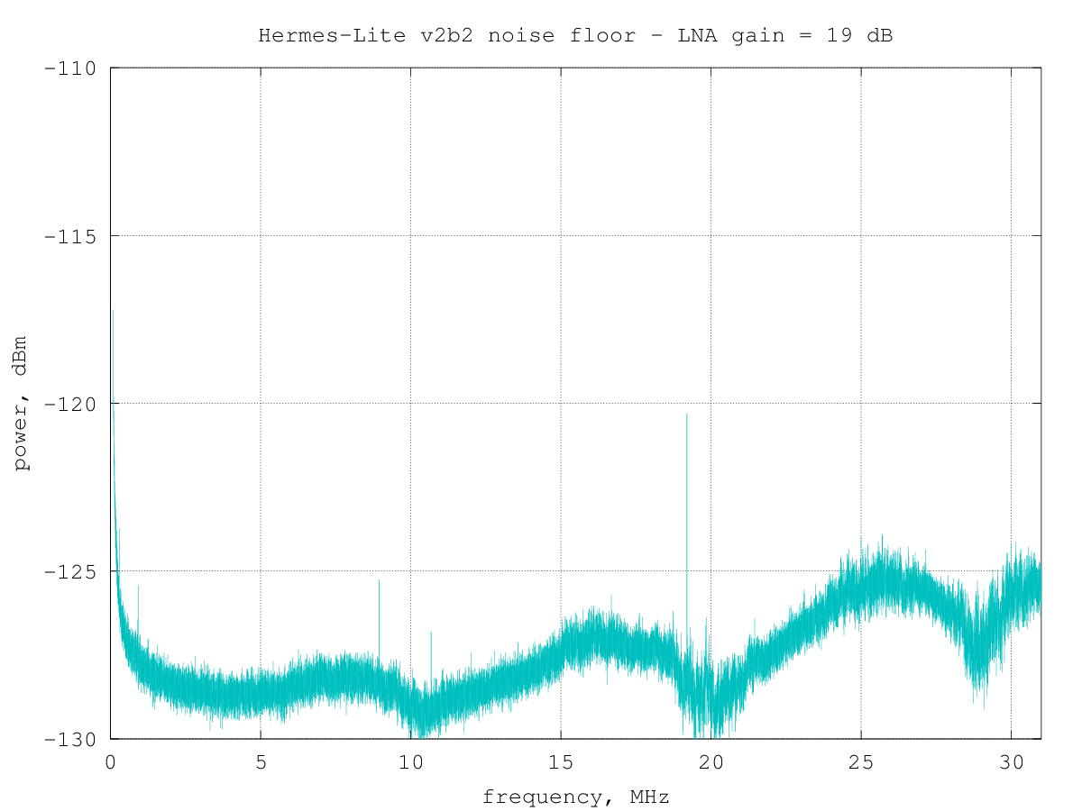
From the graph, only a few spurs can be seen, summarized in the following table:
frequency, MHz      dB above noise floor
    0.101                3.3
    0.29400              2.2
    0.94250              2.3
    8.9525               3.1
   10.67950              2.2
   19.20000              7.9
the table above shows spurs which are at least 2 dB above the local median noise floor.
The low spur around 940 kHz is likely due to one of the on-board DC/DC converters, like a smaller one (not listed above) around 910 kHz.
The noise floor shows also some ripple which was not present in the previous Hermes-Lite version.
Noise floor vs. RxPGA gain setting
In the graphs below measurements were taken every 25 kHz to decrease the overall measurement time; for this reason, some spurs seen above are not recorded here.
The AD9866 internal RX amplifier (RxPGA) gain can be programmed to -12 dB to 48 dB in 1 dB steps. Here is the measured RX noise floor for every gain step:
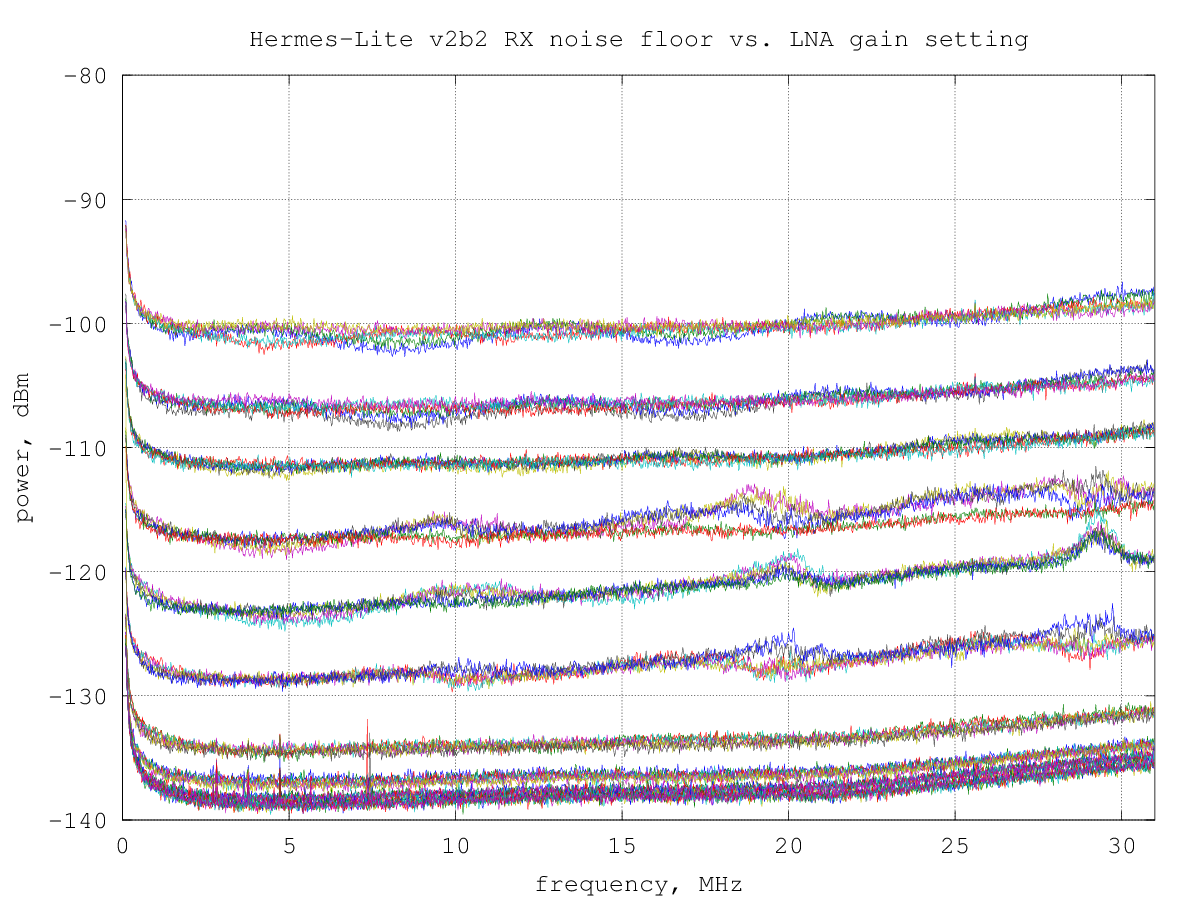
it's interesting to note that several gain steps give practically the same noise floor. This is likely due to the internal RX architecture of the AD9866, where three amplifier stages are cascaded to obtain the overall gain; changing the gain of the first stage has a large impact on the overall noise figure, while changes in the following stages are masked by the noise of the first stage.
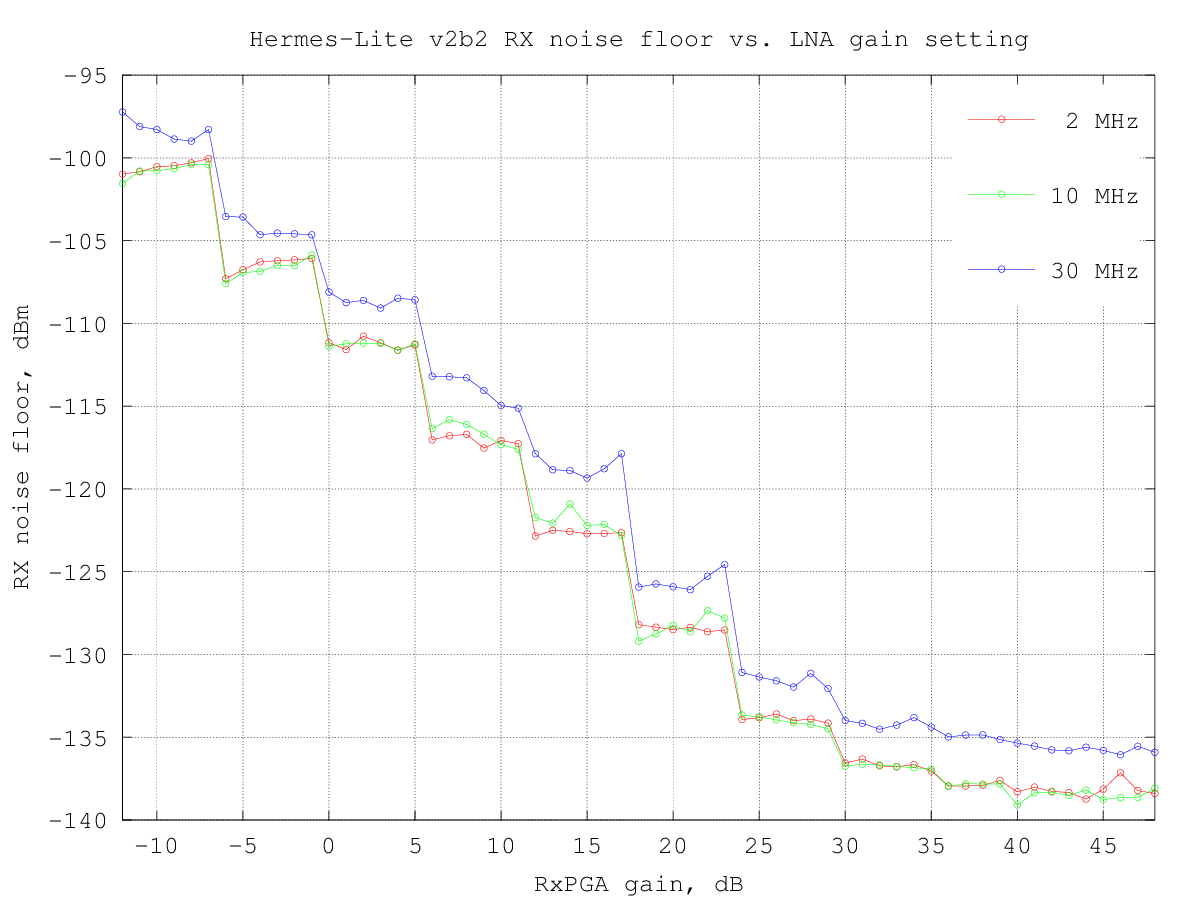
We can look at these data also by plotting the RX noise floor vs. the RxPGA gain for a few selected frequencies:
the same data showing the RX noise figure vs. the RxPGA gain:
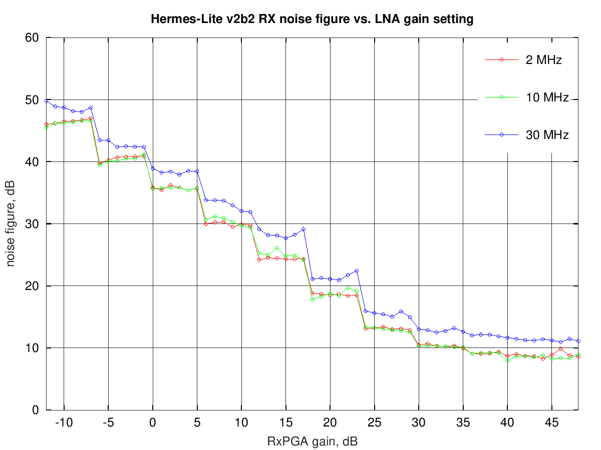
from these graphs it's clear that RxPGA gains above 30 dB bring little improvement in the receiver noise floor and, on the other end, will make frontend more prone to IMD.
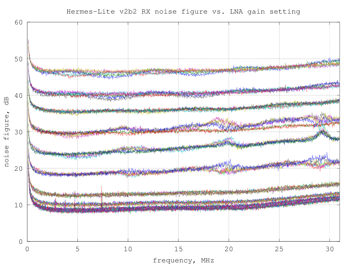
Noise figure over frequency vs. RxPGA gain setting
The noise floor data above can be equivalently expressed using the noise figure, which quantifies how much the receiver noise is higher than the theoretical minimum value due to the thermal noise.
The thermal noise floor at ambient temperature is about -174 dBm per hertz of bandwidth; since the measurement bandwidth used was 500 Hz, the thermal noise in this bandwidth is -174+10log(500) = -147 dBm.
By comparing the theoretical thermal noise floor with the measured noise floor, a graph of the noise figure over frequency for the various RxPGA gain steps is obtained:
RX gain over frequency vs. RxPGA gain setting
The following graph shows the RX gain over frequency for RxPGA gain settings from -12 dB to 48 dB, in 1 dB steps.
The 0 dB point has arbitrarily been placed to have 0 dB at 10 MHz with a RxPGA gain setting of 0 dB.
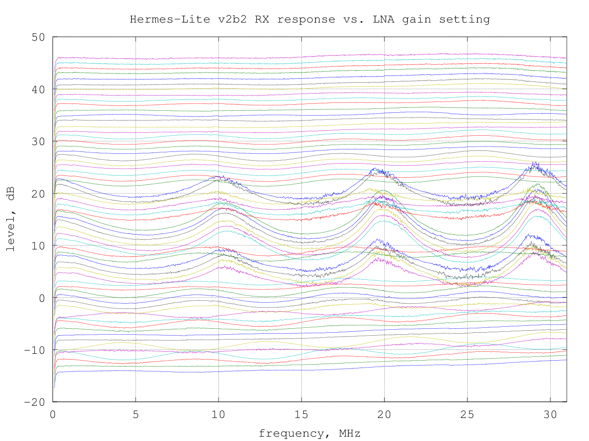
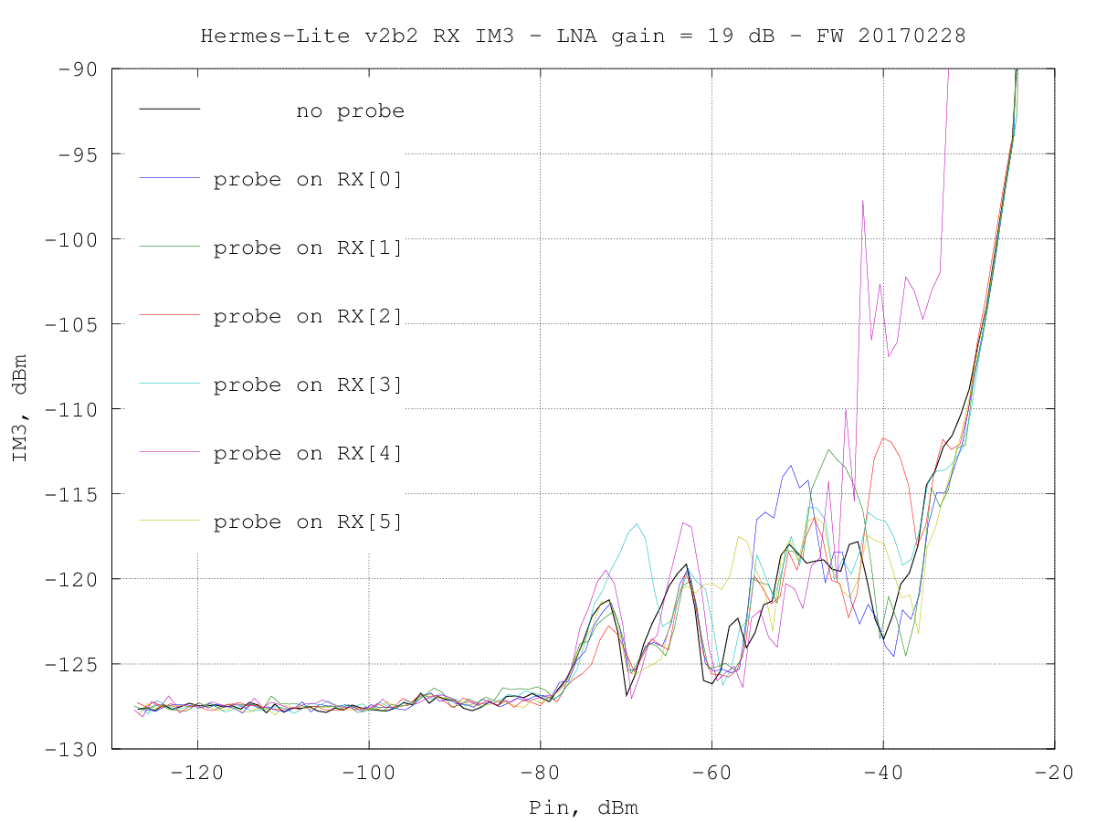
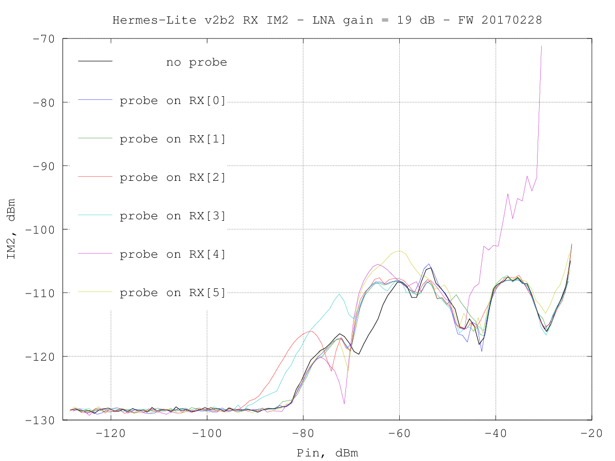
The origin of the ripples in the response at high frequency for some gain settings was not understood when the measurement was taken. After some time it became clear that these are due to crosstalk between the AD9866 digital output lines and the RF input. This crosstalk influences also the intermodulation ditortion measured in the lab, with only clean sinewave signals, as detailed below.
The next Hermes-Lite v2.0 version (beta 3) had some changes in the PCB layout to try to improve this.
IMD due to the digital bus activity
using FW 20170228
TX measurements
...under construction