IN3OTD's web site
...under perpetual construction.

Coil capacitance calculations example
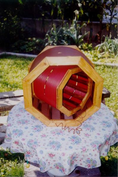
When me and my brother IN3LBQ finished building our variometer we were eager to check the actual inductance of the coils, in order to be sure it was enough to bring our vertical antenna to resonance on the 137 kHz band. But it was also clear that such a big structure will have also a not-so-small parasitic capacitance, that could affect the measured inductance, so we decided to resonate the coils with several different capacitances and use the previously described method to estimate both the true inductance and distributed capacitance.
The following table shows the measured resonance frequencies with three different external capacitances in parallel for the two variometer coils alone and for the assembled variometer in its minimum and maximum inductance configurations:
| Parallel capacitance | outer coil | inner coil | variometer at max. inductance | variometer at min. inductance |
|---|---|---|---|---|
| Cp1 = 18 pF | 375 kHz | 647 kHz | 207 kHz | 405 kHz |
| Cp2 = 518 pF | 153 kHz | 230 kHz | 99 kHz | 177 kHz |
| Cp3 = 1318 pF | 100 kHz | 149 kHz | 67 kHz | 117 kHz |
With the aid of the Inductor Capacitance and Inductance Estimation form the coils capacitance and inductance were computed for different combinations of the external parallel capacitance; the values are reported in the following table:
| Parallel capacitance | outer coil | inner coil | variometer at max. inductance | variometer at min. inductance |
|---|---|---|---|---|
| Cp1, Cp2 | 1804 µH 82 pF |
837 µH 54 pF |
3986 µH 130 pF |
1308 µH 100 pF |
| Cp1, Cp3 | 1810 µH 82 pF |
831 µH 55 pF |
3886 µH 134 pF |
1304 µH 100 pF |
| Cp2, Cp3 | 1813 µH 79 pF |
828 µH 61 pF |
3823 µH 158 pF |
1302 µH 103 pF |
| max. error | 0.28 % 2.5 % |
0.60 % 7.6 % |
2.3 % 12.3 % |
0.26 % 2.0 % |
The last row shows the maximum error between the three computed values of true inductance and distributed capacitance for the four different coils configuration. Note the very good agreement between the inductance values, except for the variometer at max inductance case, where the measured resonance frequencies with Cp2 and Cp3 were quite close; since the calculations are based on the relative frequency differences, a small error in the readings may lead to a large error in the estimated inductance. For example, if a resonant frequency of 66.5 kHz is used in the calculation instead of 67 kHz the error in the estimated inductance will decrease to 1.3 %. The distributed capacitance estimations may be also considered in good agreement, taking into account that these values (differently from the true inductance) depend also on the exact parallel capacitance values, which were not measured but the nominal values were used instead. Also here, if we use a resonant frequency of 66.5 kHz instead of 67 kHz for the variometer at max inductance case the estimated distributed capacitance error decreases, to 4 % .