Meet RadioDek!
RadioDek is a computer controlled four channel switching device designed for 12V radio power circuits but it is capable of up to 150V@30A AC it is a DIY project that anyone can build!
RadioDek is a computer controlled four channel switching device designed for 12V radio power circuits but it is capable of up to 150V@30A AC it is a DIY project that anyone can build!
How mobirise works?
The current releases are as follows:
Windows executable: version 3.0
Linux native install: version 4.2
Arduino firmware: version 2.2
Check GitHub for the latest release of the source code, at the time of writing it was version 4.6
NOTE: at the moment the versions of the desktop app HAVE to match the firmware version as there is no backwards compatibility.
Unless you are using versions 2.3 or 3, these versions require firmware version 2.2 to work.
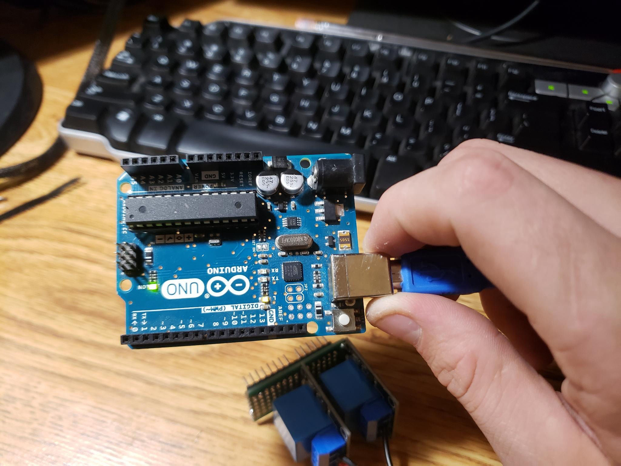
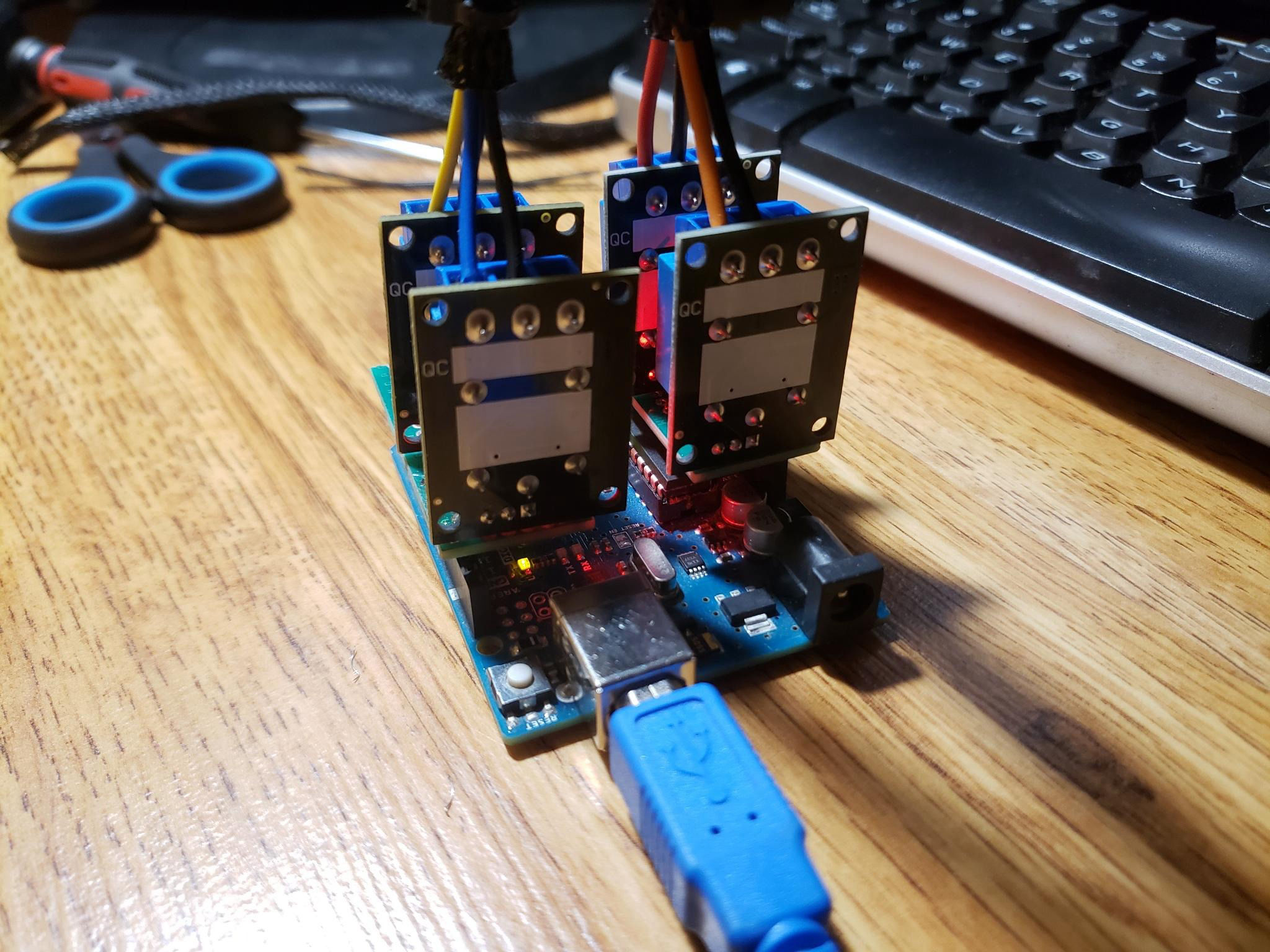
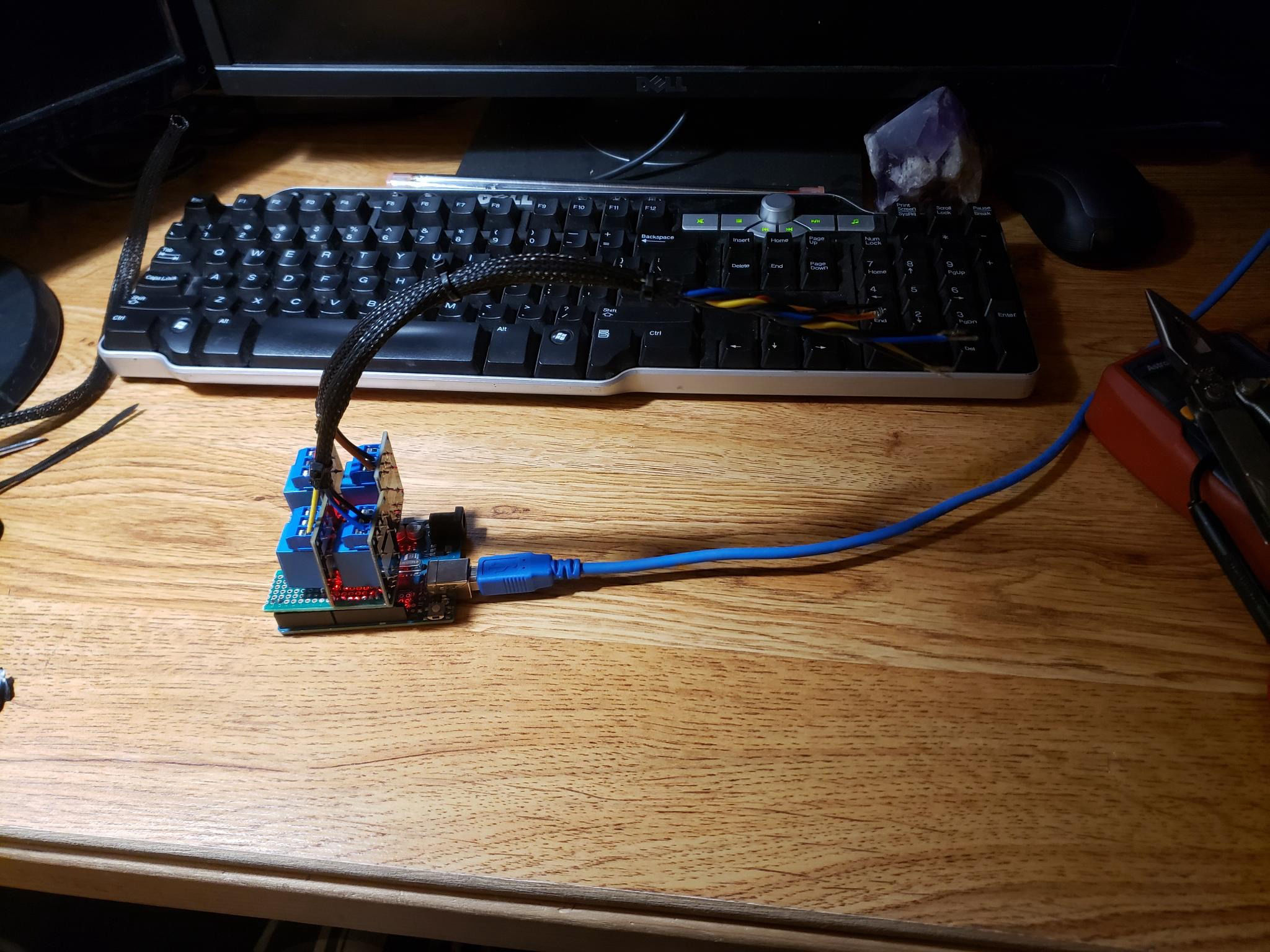
RadioDek is a device that utilizes the serial line functionality of the Arduino board and the native Python that the app is written in to be able to automate the flow of power in you shack in the form of "Deks" with the click of a button in your computers system tray!
To build a RadioDek module you will need:
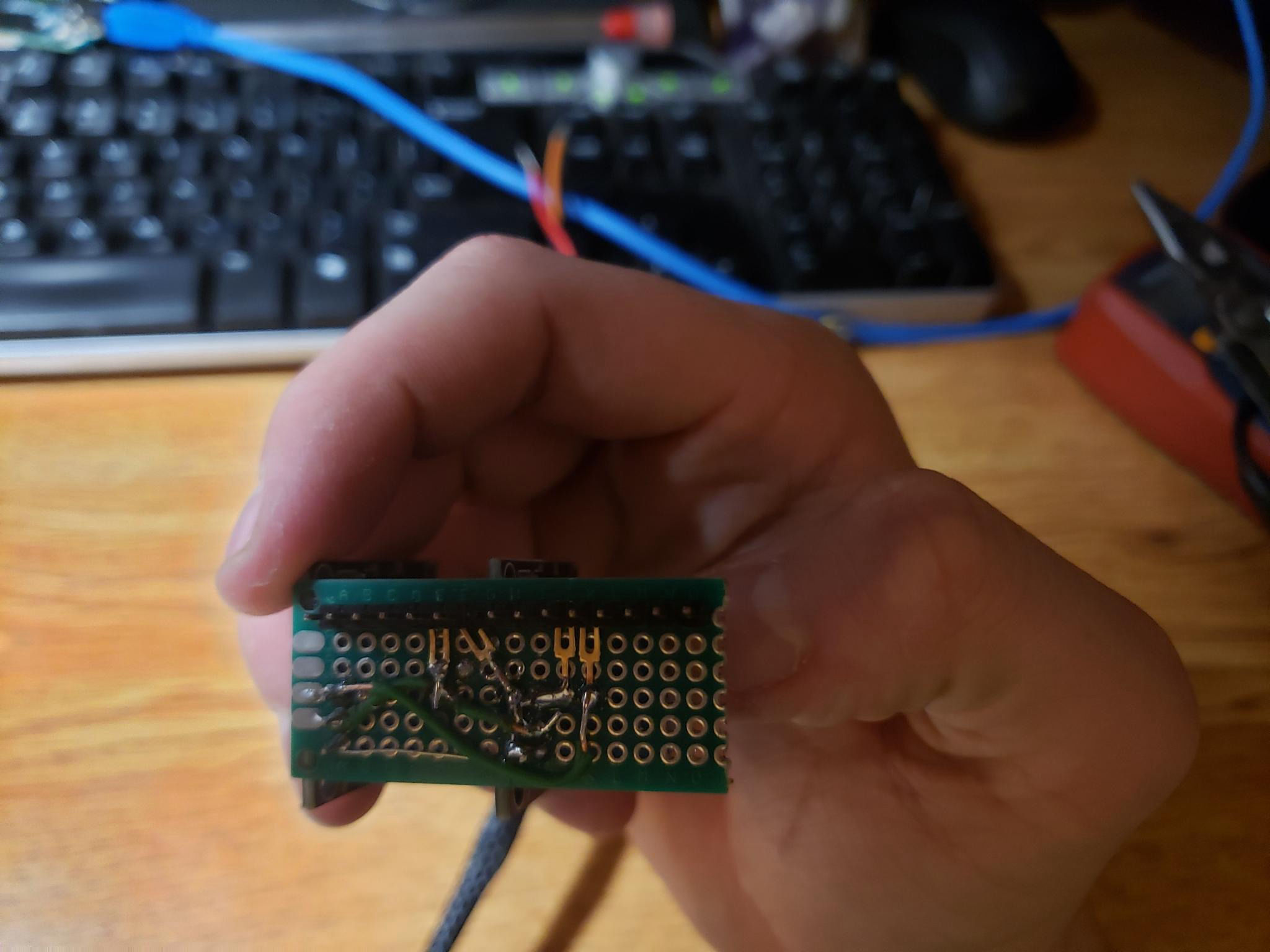
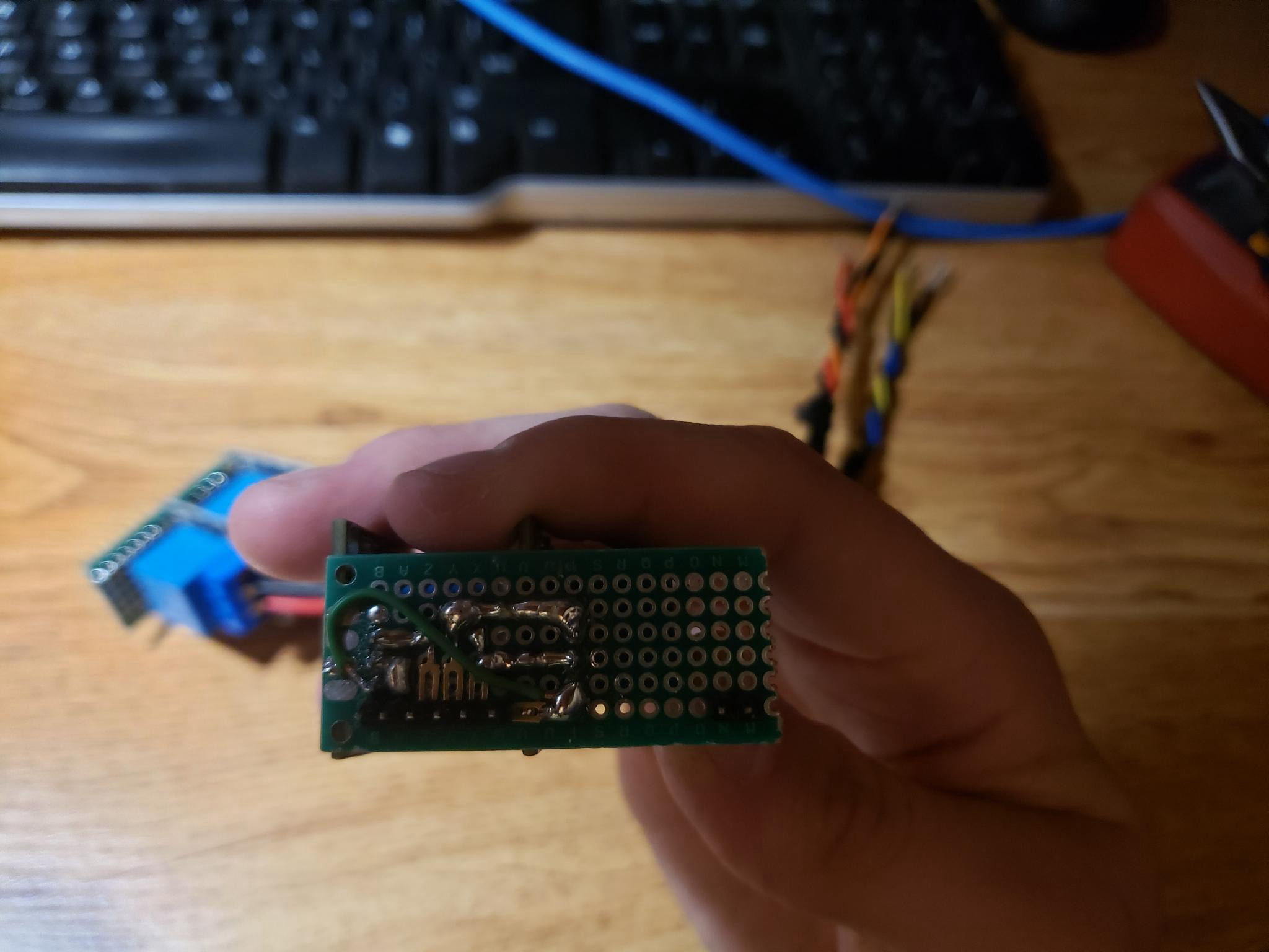
1. Some creativity, I am not going to document how I built mine as at the time I had sub-par tools and it came out pretty bad looking in the circuit.
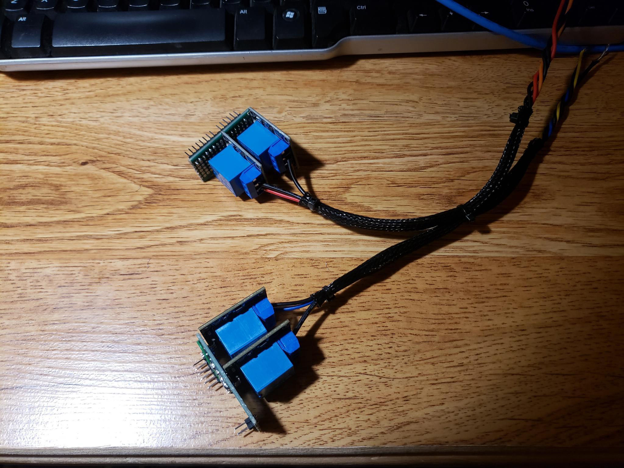
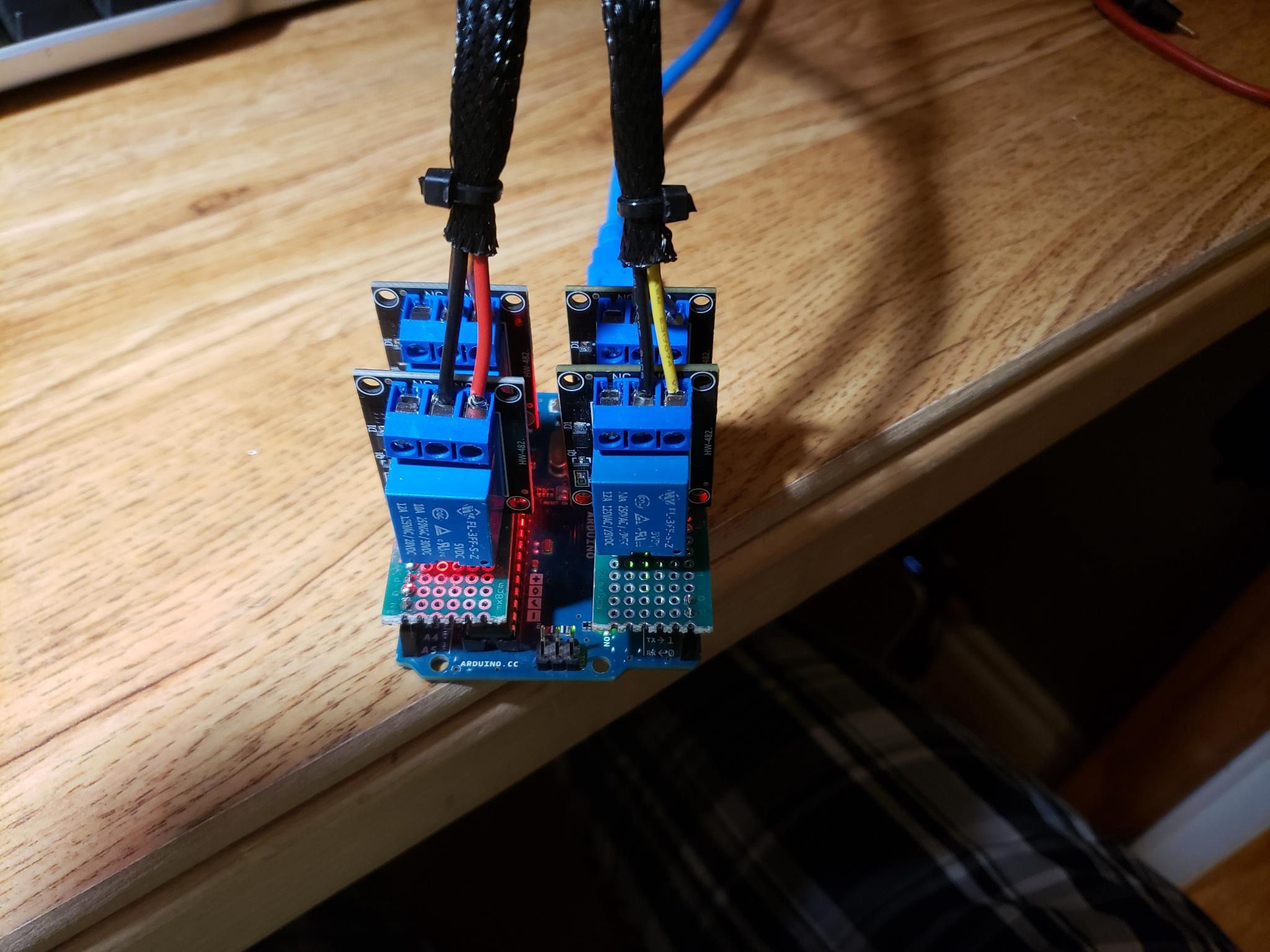
2. 4 relays rated at least 12V@20A with a 5V drive power.
3. Any device capable of being programed with the Arduino IDE that has digital output pins.
4. A computer.
5. Basic knowledge of the Arduino and Python programing languages (only if you plan to compile it your self).
For the sake of those windows users that do not want to mess around with the programing I have uploaded the pre-compiled .exe program file to GitHub for the system tray app as well as the firmware for the Arduino feel free to just download the app! However if you want to customize the menu entry's and what serial port the program uses you will have to compile the code your self (this is now being replaced with a config file that you can change without recompiling in some release versions, check GitHub for more info on this). I will leave instructions for how to do that per system below.
The circuit: (on locked config systems)
relay 1: drive pin connected to digital pin 12.
relay 2: drive pin connected to digital pin 11.
relay 3: drive pin connected to digital pin 14(A0).
relay 4: drive pin connected to digital pin 15(A1).
Note that you can change this config in the Arduino firmware before uploading but these are the plug'n'play settings.
Digital pin 13 and digital pin 10 are set to high on startup and can be used and a 5V power source for your relay drive if you opted to the module style relays like me.

© Copyright 2023 KL5IS - All Rights Reserved

Made with
Drag and Drop Website Builder