144 MHz Omnidirectional Horizontal Antennas - Part
1
NEC Model Comparisons of Single Halo, Turnstile and
Eggbeater Omnidirectional Horizontally Polarized
Antennas at 0.5λ for 144 MHz
by Dr. Carol F. Milazzo, KP4MD (posted 05 January 2013)
E-mail: [email protected]
INTRODUCTION
The halo (HO Loop), turnstile, eggbeater and Big Wheel are
omnidirectional horizontally polarized antennas used for
weak signal VHF terrestrial communications. Cebik3
duly described the benefits and problems of each of
these antenna designs. These antennas can be
stacked to increase gain at low elevation angles and to
decrease sensitivity to noise from high elevation
angles.
This study in six parts presents NEC models that
compare the expected performance of these
antennas. Each antenna was modeled with 4nec2
singly at 0.5λ and at 1λ height and as a stacked pair at
0.5λ and 1λ above a simulated ground. We used
variables and the GH (helix) and GM (move) NEC commands
to facilitate customization and the use of the optimizer
function.
|
- Single
Halo,
Turnstile and Eggbeater at 0.5λ NEC Models
- Single
Halo,
Turnstile and Eggbeater at 1.0λ NEC Models
- Stacked
Halo,
Turnstile and Eggbeater Antenna NEC Models
- Single
Turnstile,
Triangle and Wheel at 0.5λ NEC Models
- Single
Turnstile,
Triangle and Wheel at 1.0λ NEC Models
- Stacked
Turnstile,
Triangle and Wheel Antenna NEC Models
|
|
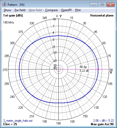
1. 144 MHz single Halo Antenna at 0.5λ horizontal
polarization radiation pattern calculated by NEC Model.
|
2. 144 MHz single Turnstile Antenna at 0.5λ horizontal
polarization radiation pattern calculated by NEC Model.
|
3. 144 MHz single Eggbeater Antenna at 0.5λ horizontal
polarization radiation pattern calculated by NEC Model.
|
|
4. 144 MHz single Halo Antenna at 0.5λ vertical
polarization radiation pattern calculated by NEC Model.
|
5. 144 MHz single Turnstile Antenna at 0.5λ vertical
polarization radiation pattern calculated by NEC Model.
|
6. 144 MHz single Eggbeater Antenna at 0.5λ vertical
polarization radiation pattern calculated by NEC Model.
|
|
7. 144 MHz single Halo Antenna at 0.5λ azimuth pattern
calculated by NEC Model.
|
8. 144 MHz single Turnstile Antenna at 0.5λ azimuth
pattern calculated by NEC Model.
|
9. 144 MHz single Eggbeater Antenna at 0.5λ azimuth
pattern calculated by NEC Model.
|
|
10. 144 MHz single Halo Antenna at 0.5λ elevation
pattern calculated by NEC Model.
|
11. 144 MHz single Turnstile Antenna at 0.5λ elevation
pattern calculated by NEC Model.
|
12. 144 MHz single Eggbeater Antenna at 0.5λ elevation
pattern calculated by NEC Model.
|
|
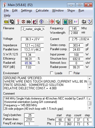
13. 144 MHz single Halo Antenna at 0.5λ 4nec2
Calculations.
|
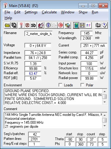
14. 144 MHz single Turnstile Antenna at 0.5λ 4nec2
Calculations.
|
15. 144 MHz single Eggbeater Antenna at 0.5λ 4nec2
Calculations.
|
CM 144 MHz Single Halo Antenna at 0.5
lambda NEC model by Carol F. Milazzo, KP4MD
CM Horizontal orientation (using GH command)
CM Frequency = 145.000 MHz
CM 26-side polygon (40 inch loop with 1.5 inch gap)
CM Simulated good ground
CM http://www.qsl.net/kp4md/omnihoriz.htm
CE
SY frq=145 'Input frequency MHz
SY cir=40.21493 'Input loop
circumference inches (loop + gap)
SY r=0.5*cir/3.1415926 'Calculate
loop radius
SY dia=0.25 'Input loop wire dia.
inches
SY rad=0.5*dia 'Calculate loop
wire radius
SY n=26 'Input n-side polygon of
loop + gap
SY h=40.87 'Input height inches to
0.5 lambda
SY g=1.5 'Input gap size in inches
SY gseg=int(n*g/cir+0.5)
'Calculate gap length in segments
GH 1
n-gseg 1e-300
1e-300*(n-gseg)/n
r r
r r
rad 'First loop
GM 0
0 0
0 gseg*180/n
0 0
h 1 'Raise loop
to 0.5 lambda
GS 0
0 0.0254
GE 1
LD 5
0 0
0 58000000 '0.25
inch copper tubing
GN 2
0 0
0 4 0.01
EK
EX 0
1 (n-gseg)/2
0 0.5
0 0 'Feed point
FR 0
0 0
0 frq 0
EN
16. 144 MHz single Halo Antenna at 0.5λ NEC model.
|
CM 144 MHz Single Turnstile Antenna at 0.5
lambda NEC model by Carol F. Milazzo, KP4MD
CM Horizontal orientation
CM Frequency = 145.000 MHz
CM 21 segments per dipole
CM Simulated good ground
CM http://www.qsl.net/kp4md/omnihoriz.htm
CE
SY frq=145 'Input frequency MHz
SY len=39.815 'Input dipole length
inches
SY dia=0.25 'Input dipole dia.
inches
SY rad=0.5*dia 'Calculate dipole
radius
SY n=21 'Input segments per dipole
(must be odd)
SY nc=0.5*(n+1) 'Calculate feed
point segment
SY h=40.87 'Input height inches to
0.5 lambda
SY s=0.25 'Input separation
between each dipole in pair inches
GW 1
n 0
-len/2 h
0 len/2
h rad 'First
dipole at 0.5 lambda
GM 1
1 0
0 90
0 0
s 1 'Rotate to
form second dipole at right angle
GS 0
0 0.0254
GE 1
LD 5
0 0
0 58000000 '0.25
inch copper tubing
GN 2
0 0
0 4 0.01
EK
EX 0
1 nc
0 0
1 0 'Feed point
EX 0
2 nc
0 -1
0 0 'Feed point
FR 0
0 0
0 frq 0
RP 0
1 361
1000 76.
0. 0.
1. 0.
EN
17. 144 MHz single Turnstile Antenna at 0.5λ NEC
model.
|
CM 144 MHz Single Eggbeater Antenna at 0.5
lambda NEC model by Carol F. Milazzo, KP4MD
CM Vertical orientation (using GH command)
CM Frequency = 145.000 MHz
CM 42-side polygon loops
CM Simulated good ground
CM http://www.qsl.net/kp4md/omnihoriz.htm
CE
SY frq=145 'Input frequency MHz
SY d=29.01591 'Input loop diameter
inches
SY r=0.5*d 'Calculate loop radius
SY dia=0.5 'Input loop wire dia.
inches
SY rad=0.5*dia 'Calculate loop
wire radius
SY n=42 'Input n-polygon loop
SY h=40.66136 'Input height inches
to 0.5 lambda
GH 1
n 1e-300
1e-300 r
r r
r rad 'Form
first loop in ground
GM 0
0 90
90-180/n 0
0 0
h 0 'Raise loop
center to 0.5 lambda and rotate to orient vertically
GM 1
1 0
0 90
0 0
.25 1 'Rotate
loop 90 degrees to form second loop
GS 0
0 0.0254
GE 1
LD 5
0 0
0 58000000 '0.5
inch copper tubing
GN 2
0 0
0 4 0.01
EK
EX 0
1 n
0 0
1 0 'Feed point
EX 0
2 n
0 -1
0 0 'Feed point
FR 0
0 0
0 frq 0
EN
18. 144 MHz single Eggbeater Antenna at 0.5λ NEC model.
|
RESULTS
- All antennas had maximum lobe gains between 3.7 and
5.2 dBi of each other at 25º elevation.
- The turnstile and Eggbeater Antenna more closely
approximated an omnidirectional pattern with 0.6-0.8
dB variation in azimuth radiation while the halo
antenna exhibited a 3.2 dB differential in gain
between its major and minor axes.
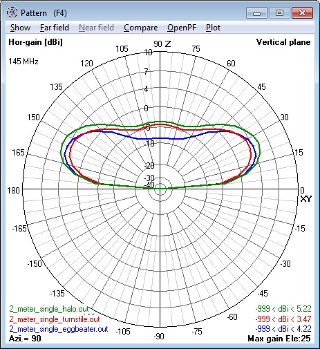
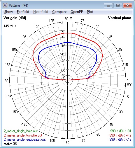
- All antenna types showed similar elevation radiation
patterns with gains of -1 to -6 dBi toward the zenith.
- The Turnstile Antenna exhibited the
least suppression of vertically polarized noise.
CONCLUSION
Although the overall expected performance of each of
the models is similar, the following differences should
be considered:
- The minor difference in performance may not warrant
incurring the greater construction complexity of the
turnstile and eggbeater antenna designs.
- The dimensions of the turnstile and eggbeater
antennas need be precise because deviations in the
antenna dimensions can significantly skew the
radiation patterns.2
|
19. Composite of all 144 MHz single Antennas at 0.5λ
azimuth patterns - horizontal polarization component
only.
|
20. Composite of all 144 MHz single Antennas at 0.5λ
azimuth patterns - vertical polarization component only.
|
REFERENCES
- The
HO
Collinear, A Horizontal Omni, Anderson R, W1HBQ
- The
Double Turnstile Antenna, Beech J, G8SEQ
- Horizontally
Polarized Omni-Directional Antennas: Some Compact
Choices, Part 1, Cebik, LB, W4RNL
- Horizontally
Polarized Omni-Directional Antennas: Some Compact
Choices, Part 2, Cebik, LB, W4RNL
- Experimental
Omnidirectional Antennas for 6-Meters, Cebik,
LB, W4RNL
- 144 MHz Halo Antenna,
Milazzo C, KP4MD
APPENDIX: NEC MODEL FILES
- 144
MHz single Halo at 0.5λ NEC Model
- 144 MHz single
Turnstile at 0.5λ NEC Model
- 144 MHz single
Eggbeater at 0.5λ NEC Model
LINKS
- Single Halo,
Turnstile and Eggbeater at 0.5λ NEC Models
- Single
Halo, Turnstile and Eggbeater at 1.0λ NEC Models
- Stacked
Halo, Turnstile and Eggbeater Antenna NEC Models
- Single
Turnstile, Triangle and Wheel at 0.5λ NEC Models
- Single
Turnstile, Triangle and Wheel at 1.0λ NEC Models
- Stacked
Turnstile, Triangle and Wheel Antenna NEC Models
- Omnidirectional
Horizontal
Antenna Photo Album
|
21. Composite of all 144 MHz single Antennas at 0.5λ
elevation patterns - horizontal polarization component
only.
|
22. Composite of all 144 MHz single Antennas at 0.5λ
elevation patterns - vertical polarization component
only.
|
Summary
of Results
|
|
Halo
|
Turnstile
|
Eggbeater
|
Cebik Triangle
|
Cebik Wheel
|
| Single
0.5λ |
Single 1.0λ
|
Stacked
|
Single
0.5λ |
Single 1.0λ |
Stacked
|
Single
0.5λ |
Single 1.0λ |
Stacked
|
Single
0.5λ |
Single 1.0λ |
Stacked
|
Single
0.5λ |
Single 1.0λ |
Stacked
|
Major lobe elevation (degrees)
|
25
|
15
|
15
|
25
|
15
|
15
|
25
|
15
|
15
|
25
|
15
|
15
|
25
|
15
|
15
|
Major lobe gain (dBi)
|
2.0-5.2
|
2.8-6.0
|
4.8-7.9
|
2.9-3.7
|
3.1-4.1
|
5.8-6.8
|
3.7-4.3
|
4.8-5.4
|
6.3-7.0
|
4.7-4.9
|
5.9-6.1
|
6.8-7.1
|
4.8-4.9
|
6.0-6.1
|
6.9-7.0
|
Gain at 90º elevation
(dBi)
|
-3.5
|
-3.5
|
-40
|
-1.2
|
-1.3
|
-33
|
-5.4
|
-5.6
|
-21
|
-1000
|
-1000
|
-1000
|
-1000
|
-1000
|
-1000
|
|


