4CX1500B RF Deck
Servo Motor tuning -- The tunable elements in this amplifier were originally operated by stepper motors -- size 23 for all except the grid coil which was a size 15. A sine drive was used for smooth & silent operation relay switched between all five motors. I had used gearhead motors in later projects and upon updating this unit these were incorporated into the design.
Heater -- A voltage ramped heater soft start is included. The operation of this circuit is explained in detail here. This implementation uses the first circuit described modified to allow the drain of the FET to be directly grounded -- Both leads of the switching power supply float in this instance. A pair of transistors are also added to connect the negative remote sense line to the switching power supply when the voltage across the power FET drops below .6 volt. The remote sense could not be directly connected to the heater with the Soft Start circuit in place as there are internal diodes in the power supply connecting the sense leads to the output leads.
Grid capacitors --
These are selected with ancient hermetically sealed mil-spec DPDT relays, with 2 Amp contacts wired in parallel, as are the two grid padding coils for 80 & 160 meters.
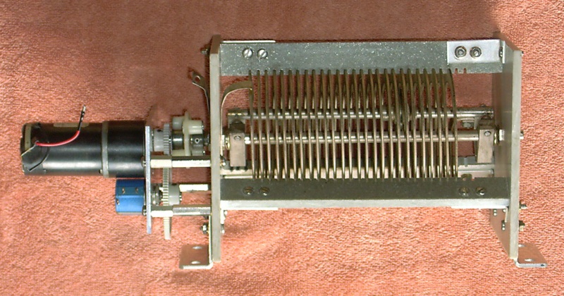
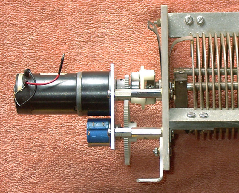
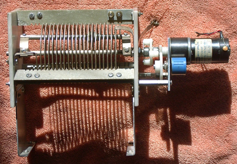
Tune & Load caps -- Vacuum caps, driven by small gearhead motors, are employed for both the tuning (7-750pF) and loading (50-3000pF) for their great range and relatively small size.
Pi-L coil --
The Pi-net is designed for a nominal Q of 12. The L point is designed for 250 ohms nominal.
Where's the plate choke!? --
The 10 meter portion of the Pi coil is comprised of a section of RG-401. The outer conductor is the coil fed through the plate coupling capacitor and the plate voltage is fed through the inner conductor. Then, a rather ordinary pie-wound 2 mHy RF choke is employed mounted directly under the tune capacitor. A detailed explanation of this technique may be seen here.
Tune (Phase) Sensor --
The gird coil current is sensed by a toroidal transfomer providing a 90 degree phase shift and combined with a sample of the plate voltage.
Load Sensor --
This is a typical grid voltage / plate voltage balance circuit. Reed relays select the individual calibration capacitors for use with a 4CX1000A or a 4CX1500B.
Fwd / Ref Power Sensor --
A cross coupled transformer design is used for wide frequency coverage.
Frequency takeoff --
A sample of the input signal is sent to the microprocessor where it is directly counted to determine the input frequency.
Temperature Sensor --
An infrared temperature sensor is aimed at the tube where the ceramic meets the plate structure.
QSK Relays --
A reed relay is employed for the input switching and a vacuum relay for the antenna switch. The relay coils are connected in series and engerized from a high voltage source, with a voltage limit across the reed relay and a current limit.
Excessive Details on the Motor Drives
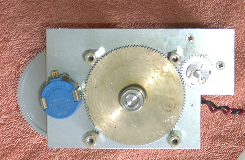
Pi & L Coils -- The endplates of the large Henry Radio roller coils were not made with great precision. To sidestep this problem the endplates were demounted then, the mounting holes, and the motor shaft position, for the new aluminum motor mount plates were just traced directly. The Pi coil plate is 3.5" x 3", the L coil plate is 3.5" x 2.5"; both parts are .094" thick. When re-assembling the roller coils ensure that the endplates rest flat against a surface, in both planes, to keep the coils true.
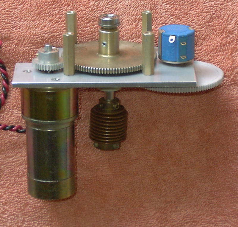
The motor plates are fastened to the Henry coil endplates with 1.375" brass spacers threaded for 6-32 screws. Spacers of that length weren't "in stock" so .5" parts and .875" parts were stacked. Brass washers are placed between the spacer and the steatite coil endplates to spread the stress and attached to the existing Henry screws that hold the coil supports in two places. The additional spacers are fastened in existing unused holes in the endplates with brass screws & washers.
Plexiglass templates for the 8xxx Pittman motors with holes for the (offset) shaft position and the mounting center facilitate layout of the motor mounts. The holes for the motor mounts are located after the main motor hole is punched using (4-40) transfer screws in the motor housing.
A Bourns 3540S 10 turn potentiometer is coupled to the Pi coil motor shaft with 40 and 108 tooth 48 pitch 1/8" thick gears. The L coil uses 40 and 84 tooth gears. The gears are installed with the hub toward the motor on the motor shaft and with the hub away from the potentiometer on the potentiometer shaft. The motor mount holes required just a bit of filing to clear the hub on the small gear. The hole positions for the potentiometers were spotted by placing the gears in position and marking the shaft locations.
The motor shafts are connected to the coil shafts with the existing nylon insulated couplings.
The Pi coil is mounted to the side of the case using the factory mounting angles.
The L coil required a pair of aluminum extensions to position it above the bypass box. These had to be shortened by 3/8" to clear the new servo box mounted at the top left rear of the amplifier.
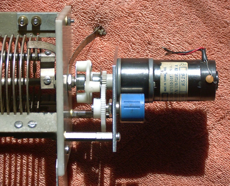
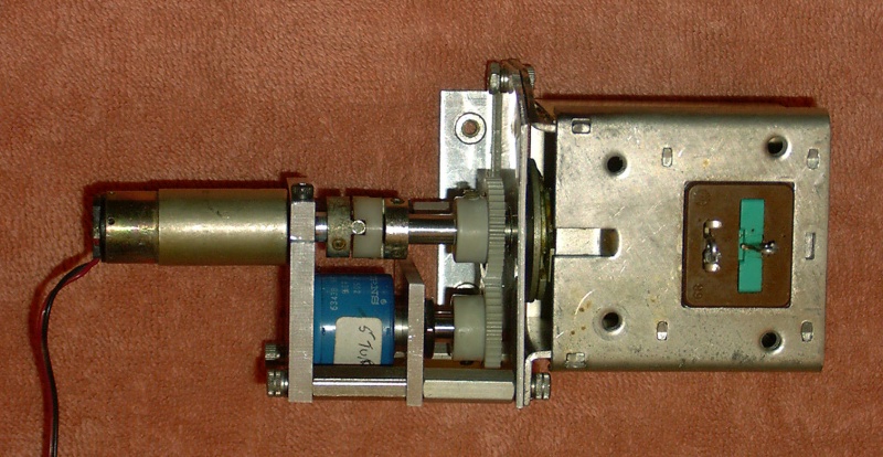
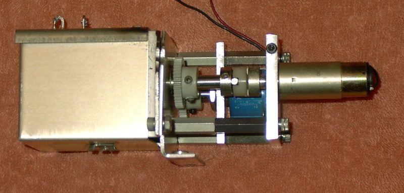
Tune & Load Capacitors --
The capacitor drives required a bit more ingenuity to fit the existing mounting configuration. The tune cap plate is 3.5" x 3", the load cap plate is 3.5" x 2.5"; both parts are .093" thick. The plates were mounted with 1" spacers to the existing stepper motor mounts.
The motors are coupled to the drive shaft with 36 & 109 tooth gears -- yes, 109's are rather uncommon but, I had a pair of them and no other use for same; 108's would work just as well to duplicate the drive. The drive shaft is supported by 1/4" ball bearings in the mounting plate and the rear grid compartment plate.
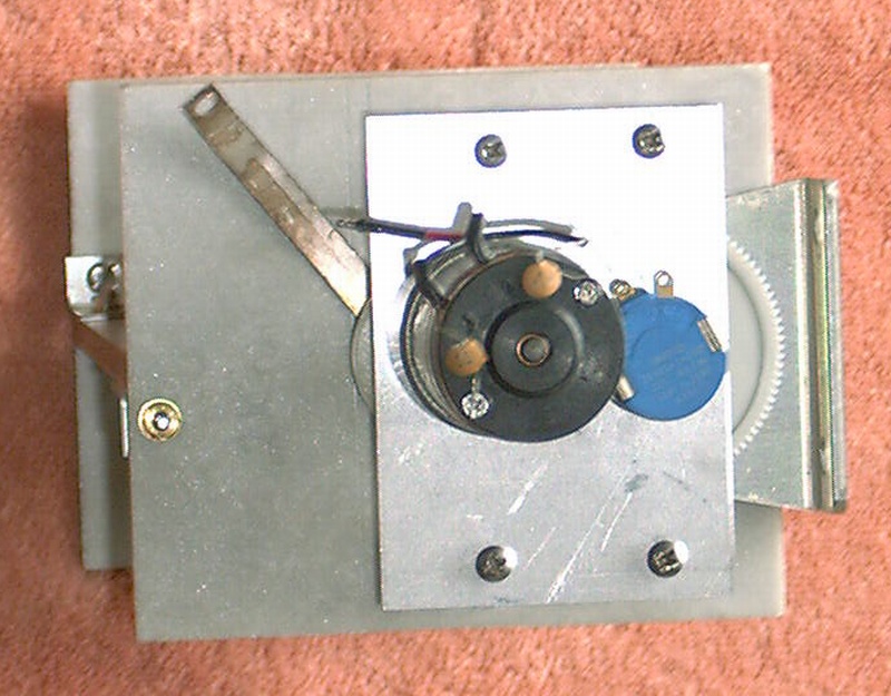
A Bourns 3540S 10 turn potentiometer is coupled to the Tune cap shaft with 48 and 108 tooth gears. The Load cap uses the same ratio. The hole locations for the potentiometers were again spotted by using the gears for spacing.
Greater precsion is realized on the holes by first punching them with a slightly undersized JC Whitney punch and then drilling to the final dimension. The motor mount holes are punched with a 1/2" Greenlee chassis punch.
The Whitney punch covers holes up to 9/32" and Greenlee punches start at 1/2". A step bit was employed for in between fractional sizes such as the 3/8" potentiometer holes.
Grid Coil --
The variable grid coil, a Mallory 416S001 Inductuner, is mounted by a custom made L bracket to the inside of the grid compartment.
A 1.75" x 1" by .125" thick aluminum plate holds the Bourns 5 turn postion potentiometer supported by two .875" spacers. A 1.625" x 1.75" x .187" thick aluminum plate, supported by two .75" spacers stacked on the potentiometer plate plus a third 1.625" spacer which bypass that plate, mounts the Swiss Micromotor with an integral 500:1 gearhead by means of an integral compression clamp formed by cutting a slot from the edge of the plate into the .277" diameter hole which fits the motor bushing. A 4-40 cap head screw tapped into the main body of the plate provides clamping force. The motor is coupled to the coil shaft with a minature flex coupling and a pair of 40 tooth, 48 pitch gears couple the coil shaft to the position pot.