IN3OTD's web site
...under perpetual construction.

Homemade SMA female calibration kit measurements
The following chapter shows several reference impedances having an SMA female port.
Some time ago I found on eBay a quite cheap lot of new old stock Molex 73251-1260 female SMA connectors; they are well suited to build some simple loads as they have a very short center pin and four standard ground legs, as they were intended to be mounted on a PCB while minimizing the connection parasitics (hence the surface-mount style center conductor).
Open
This is simply a bare SMA connector - no additional components. In theory the center conductor should be shielded from the external environment, i.e. enclosed in a conductive case, but in practice, at the relatively low frequencies involved here, this has been found to make no difference.


Short - style 1 (SnPb solder only)
This reference short circuit was built by simply flooding the back of the connector with enough solder to fill the void between the center conductor and ground. Not a very elegant way, but seems to work quite well.


Short - style 2 (Cu disk)
This is another version of the short circuit reference; a small copper disk was cut out from a thin copper tape with just the right size to fill the void between the center conductor and the surrounding ground and then soldered down. Performances seems about the same as the first version or maybe even a little worse (!).


50 Ω loads
For the 50 Ω load several possibilities were tried, using a different number of resistors in parallel, since the common wisdom is that two or three resistor in parallel are better than a single one, but I did not find any actual measurements to support this statement. Not surprisingly, that seems to be true...
Load - 1 x 49.9 ohm
A reference load built using a single Panasonic ERA3AEB49R9V resistor (49.9Ω 0.1 %, 0603 size, 100 mW max).


Load - 2 x 100 ohm
A reference load built using two Panasonic ERA3AEB101V resistors (100Ω 0.1 %, 0603 size, 100 mW max) in parallel.


Load - 2 x 100 ohm (0805 size resistors)
After building the loads with 0603-size resistors, I read that 0805 ones are supposed to behave better up to a few GHz [1] [2], so I later built a load with two 0805 resistors to check this. The picture and curve below show a reference load built using two ERA-6AEB101V thin-film resistors (100Ω 0.1 %, 0805 size, 125 mW max) in parallel.


indeed the conventional wisdom is true, and the larger size resistor shows a better return loss than the smaller ones, until about 5 GHz; however, at higher frequencies the performances degrades rapidly.
Load - 3 x 150 ohm
A reference load built using three Panasonic ERA3AEB151V resistors (150Ω 0.1 %, 0603 size, 100 mW max) in parallel.


Load - 4 x 200 ohm
A reference load built using four Panasonic ERA3AEB201V resistors (200Ω 0.1 %, 0603 size, 100 mW max) in parallel.


Calibration kit modeling for the HP 8753C
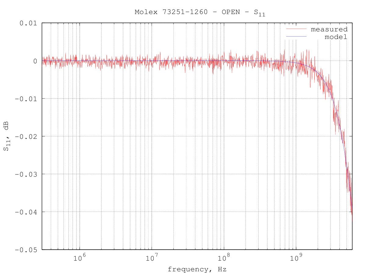
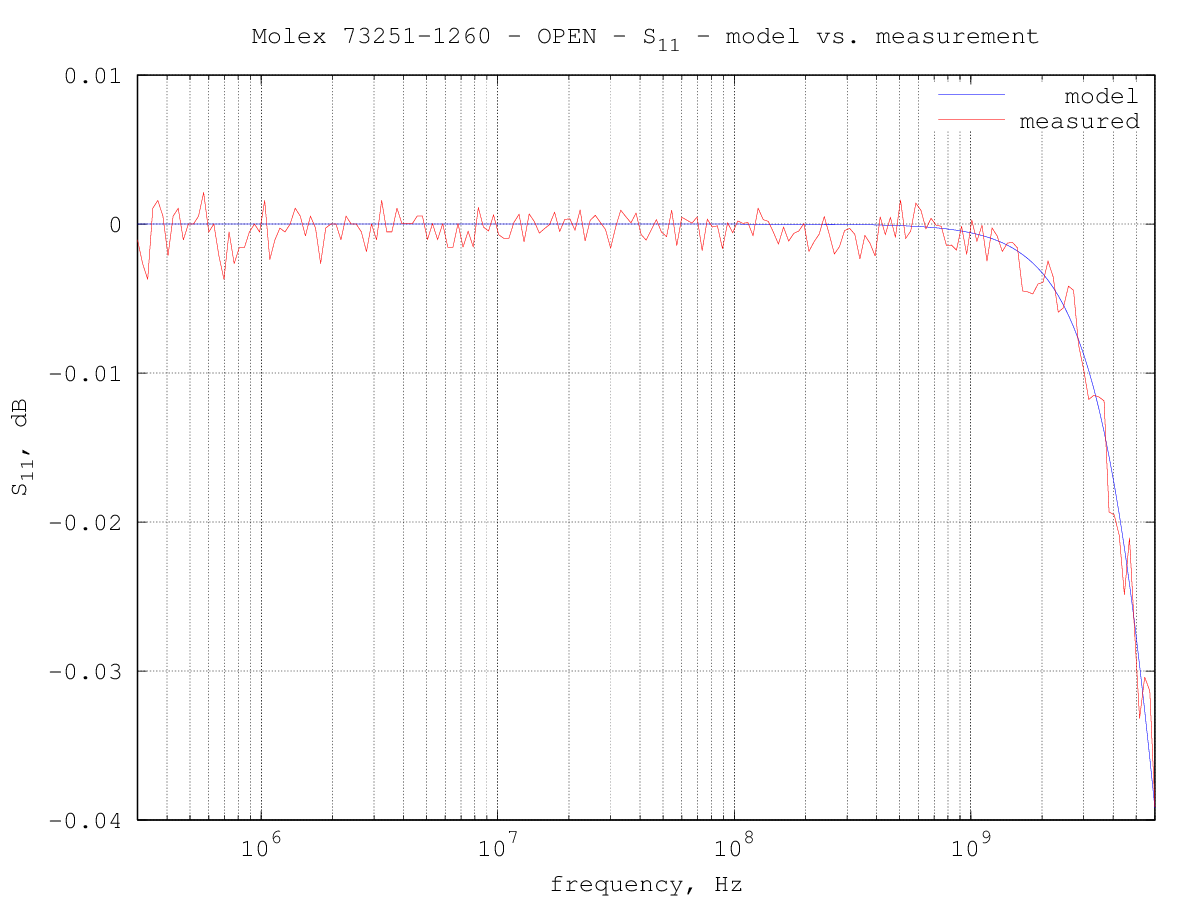
SMA female open model
The open model includes a frequency-dependent parasitic capacitance, which allows to obtain good results over a wide frequency range. In the optimization results below the offset Z0 has been fixed at 50 Ω since its value did not influence much the final results:
| offset delay | offset loss | offset Z0 | C0 | C1 | C2 | C3 |
|---|---|---|---|---|---|---|
| 35.73 ps | 2.87 GΩ/s | 50 Ω | -4.87 fF | -1140.3e-27 F/Hz | 2176.5e-36 F/Hz2 | -213.5e-45 F/Hz3 |
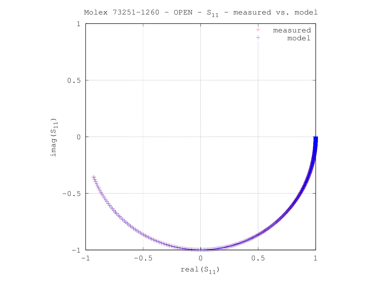
Fitting results:
This is the residual error (model S11 - measured S11) across the whole frequency range:
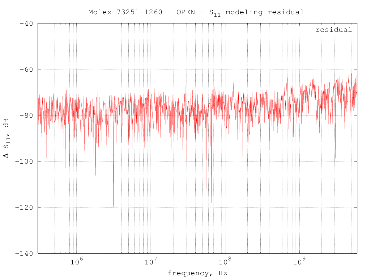
the overall RMS error is around -72 dB.
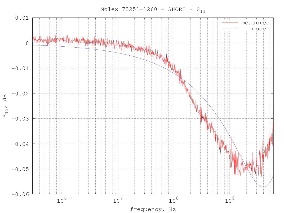
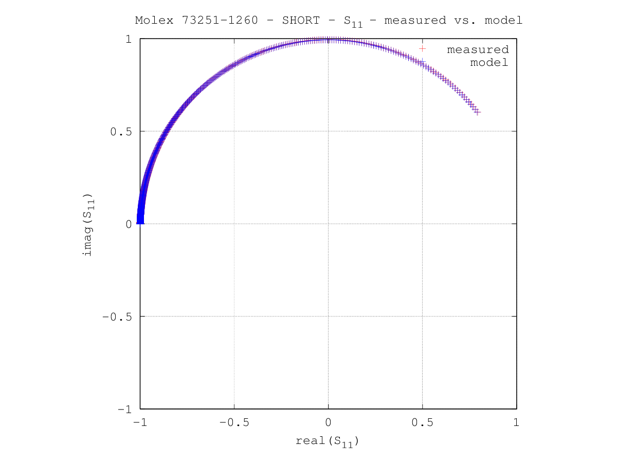
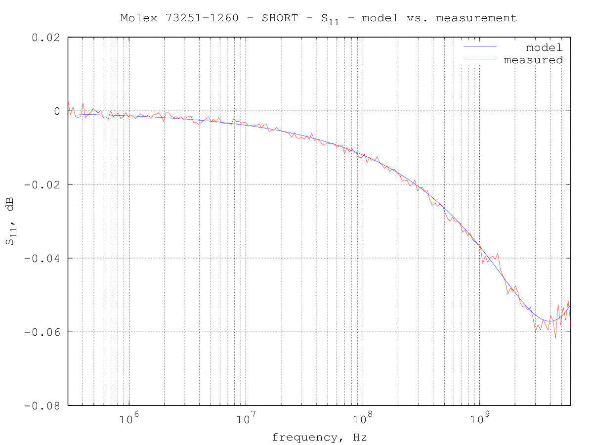
SMA female short model
As said above, the HP 8753C does not allow to specify a parasitic inductance for the short as this is assumed to be zero, so only the offset transmission line parameter can be used to model this standard behavior. Here are the optimization results
| offset delay | offset loss | offset Z0 | L0 | L1 | L2 | L3 |
|---|---|---|---|---|---|---|
| 31.6 ps | 3.4 GΩ/s | 51.9 Ω | 0 pH | 0e-24 H/Hz | 0e-33 H/Hz2 | 0e-42 H/Hz3 |
Fitting results:
This is the residual error (model S11 - measured S11) across the whole frequency range:
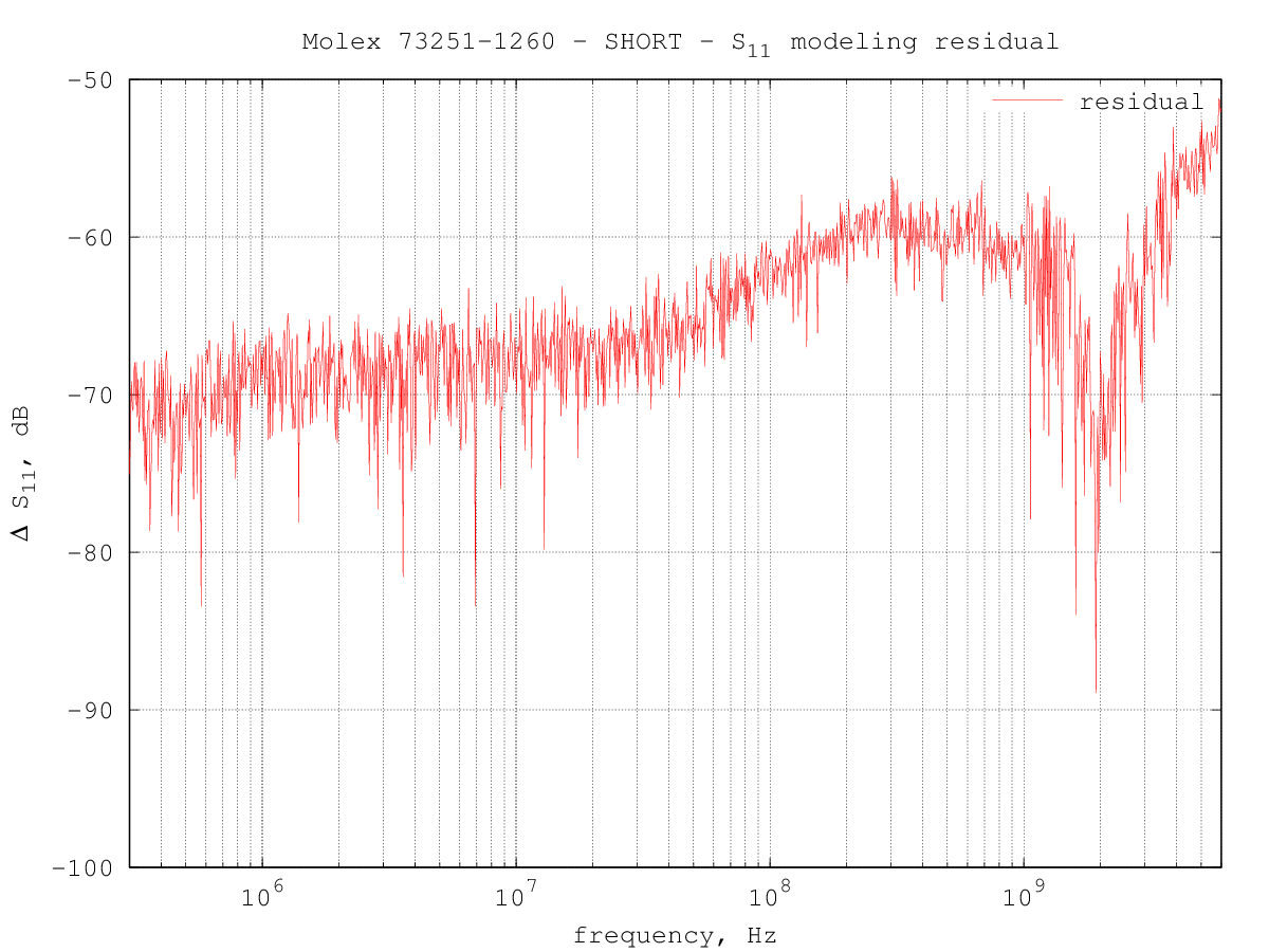
the overall RMS error is around -61 dB.
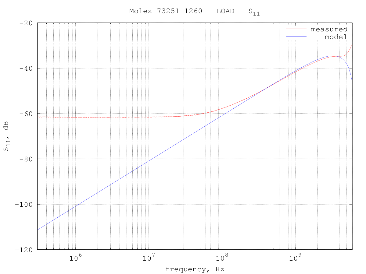
SMA female load model
Of all the loads built, the one that fitted best the 8753C load model is the one made with two 100Ω resistors in parallel, so only the results for this load are presented.
| offset delay | offset loss | offset Z0 |
|---|---|---|
| 76.6 ps | 0.0 GΩ/s | 50.95 Ω |
Fitting results:

This is the residual error (model S11 - measured S11) across the whole frequency range:

the overall RMS error is around -51 dB but the error at high frequencies becomes quite high, probably because of the parasitic capacitance that cannot be accounted for in the model.
Verification of the computed models
As a verification that the model used for calculating the models parameters corresponds to the one used internally by the 8753C VNA, I have done a 1-port calibration using the homemade standards characterized above, after having entered the computed standard coefficients in the "user kit" standard definition.
After the calibration, connecting the same loads used as calibration standards we should obtain the same S-parameters as computed for the corresponding model.
In the following, graphs for the different load standard show the computed model S-parameters and the corresponding S-parameters measured by the VNA after calibrating it with the standards definitions above.
SMA female open model
SMA female short model
SMA female load model
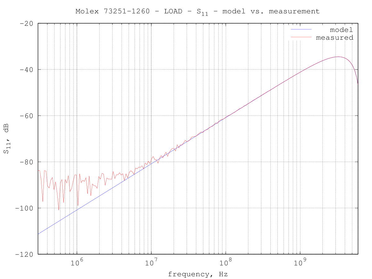
for all the three standard the computed and measured S-parameters are practically equal, meaning that the model calculations done by the GNU Octave script and the 8753C VNA is the same, as expected.
References:
| [1] | Joel Dunsmore, "Calibration for PC Board Fixtures and Probes," ARFTG Conference Digest-Spring, 45th, vol.27, pp. 56,63, 19 May 1995 |
| [2] | Sam Wetterlin, "OSL Calibration," (see the OSL_Standards.pdf" file) |