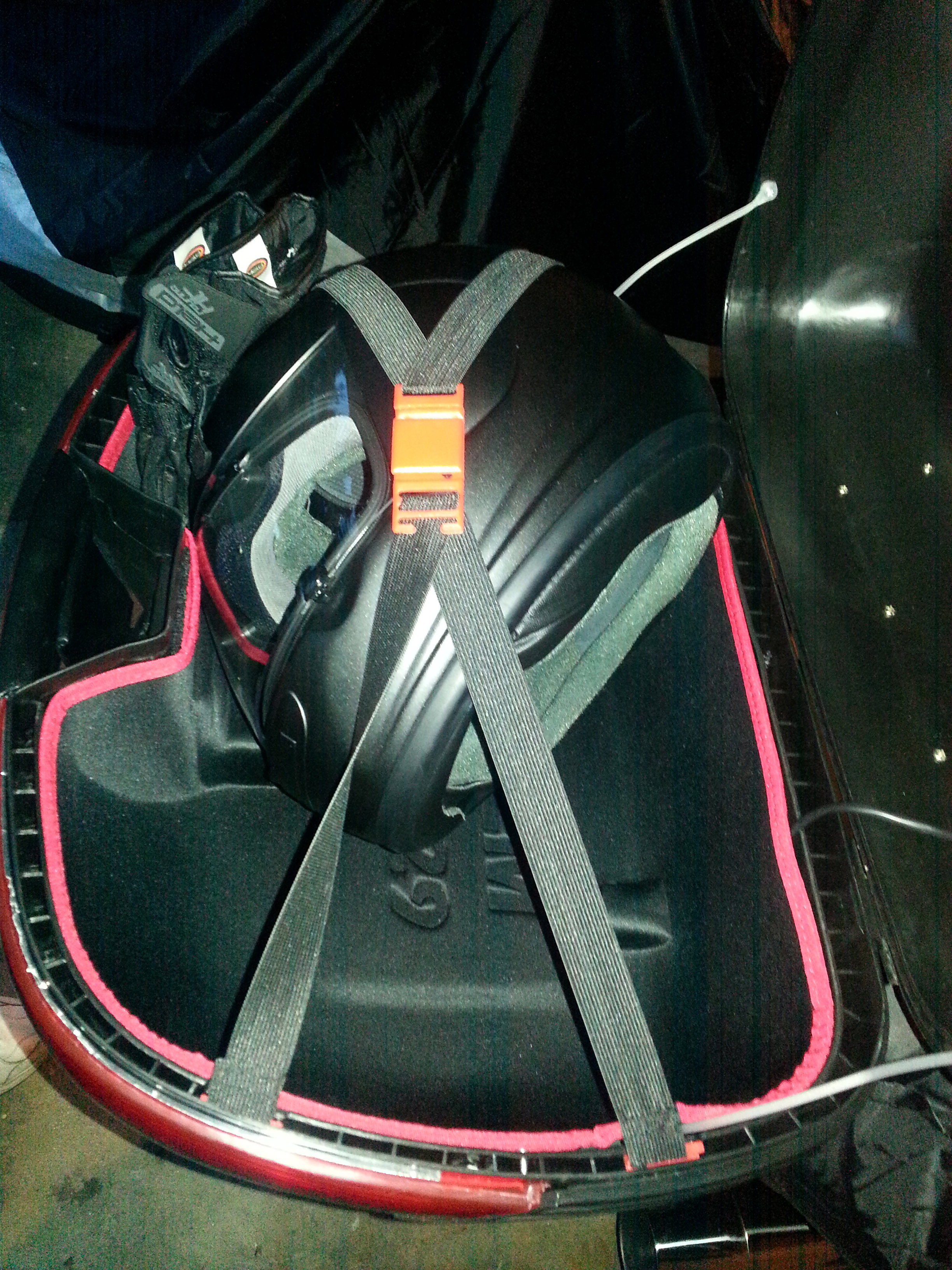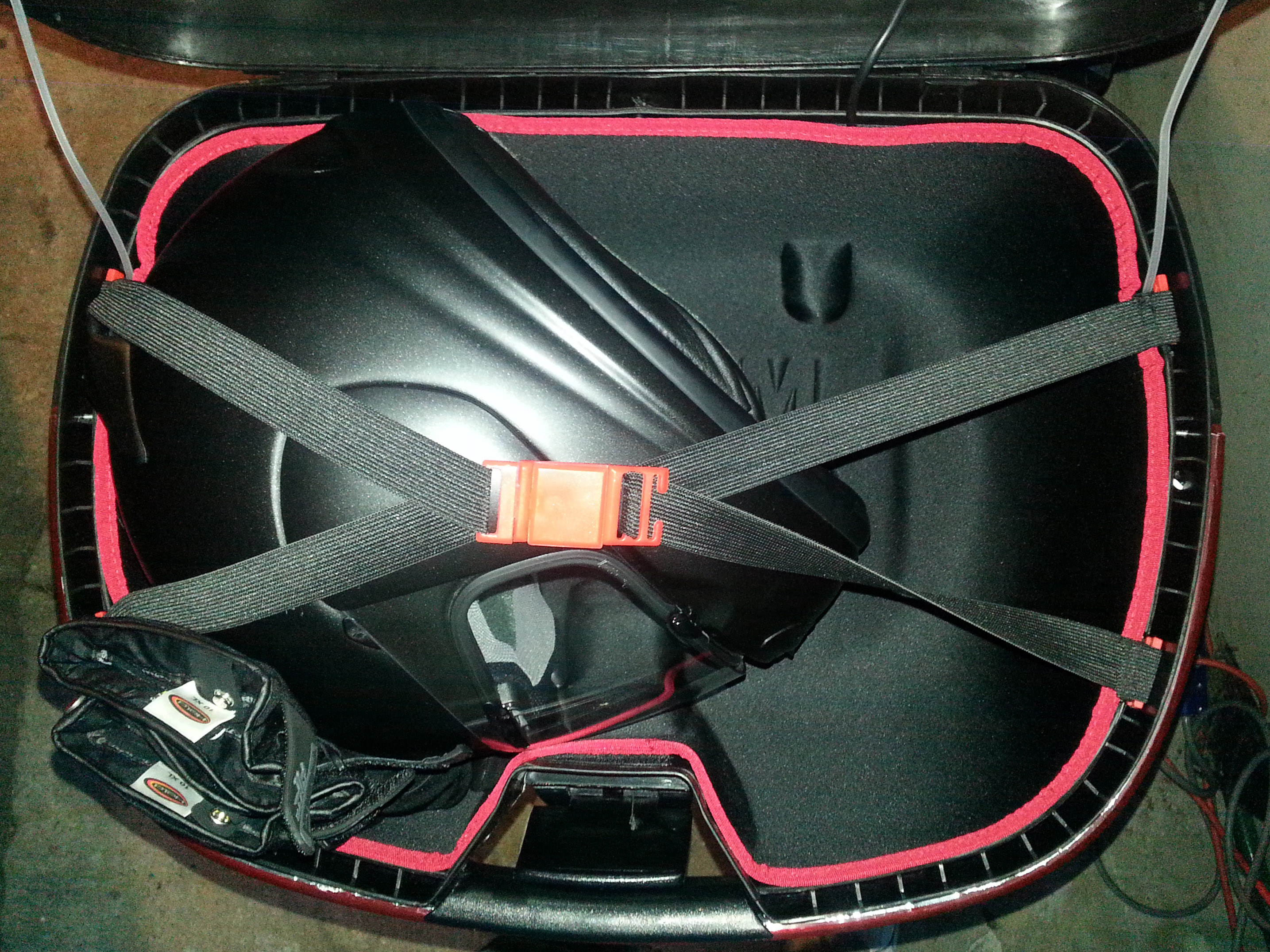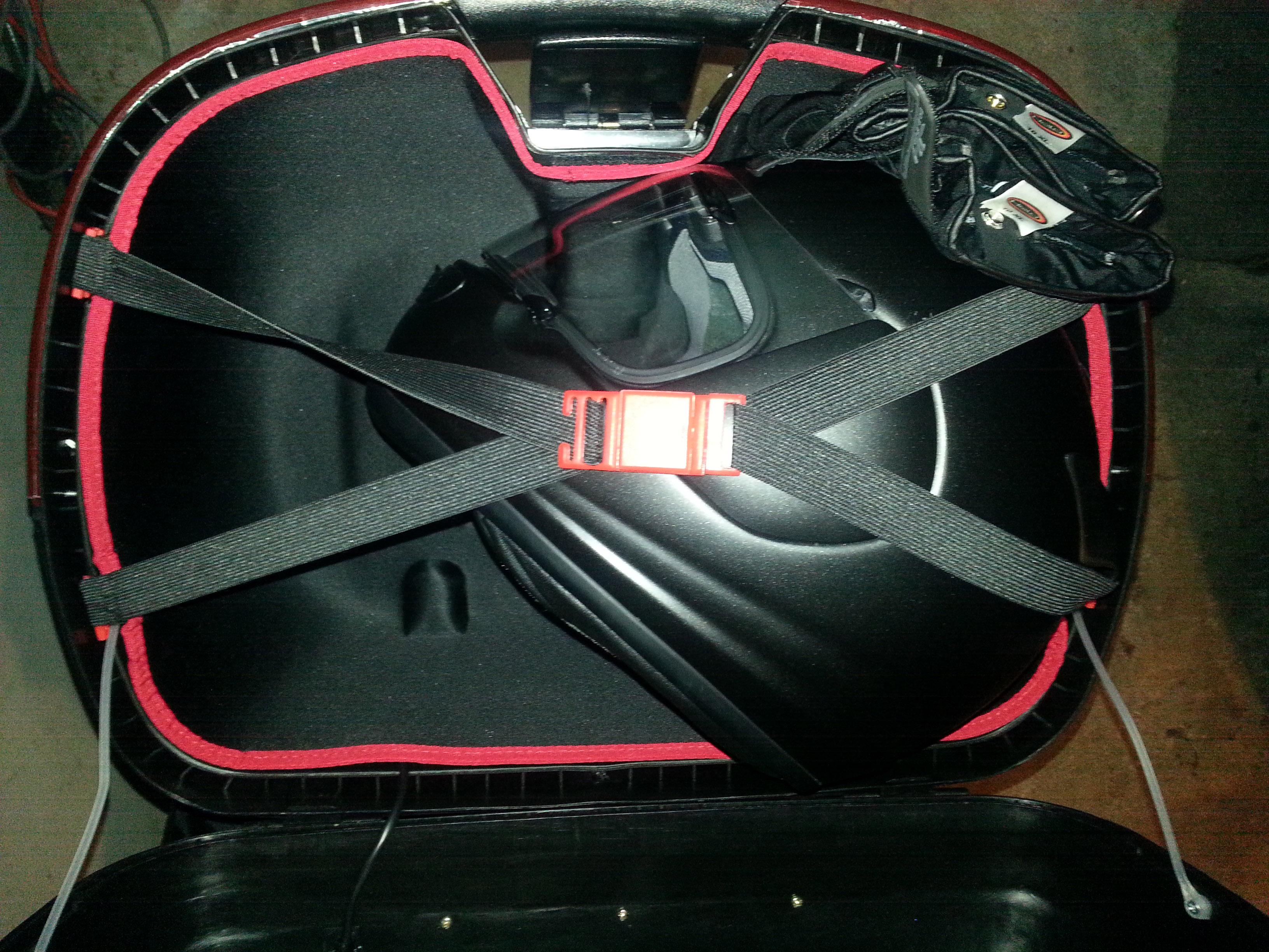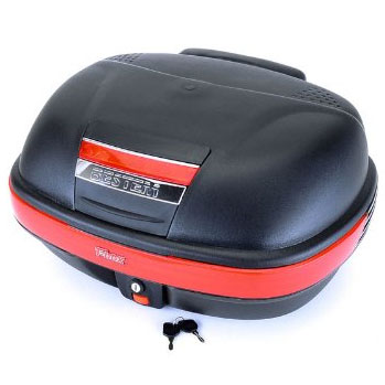
This page attempts to document my efforts to get a top box on my CTX700. Take the time to read through it and get a jist for what was done before jumping in with both feet. After reading everything I could find about top boxes and the mounts for them, I made a decision to go with the Honda OEM rear carrier and a Bestem 929 top box. Other manufacturers like Givi and Shad have specific mounts for their boxes. Using Shad's mount prevents the installation of an aftermarket seat like a Corbin. The other factor is that neither Givi or Shad provided enough mechanical information about the brackets! I purchased the 92 box with the liner. On first opening it had a chemical smell so it went outside to air out for a few days!
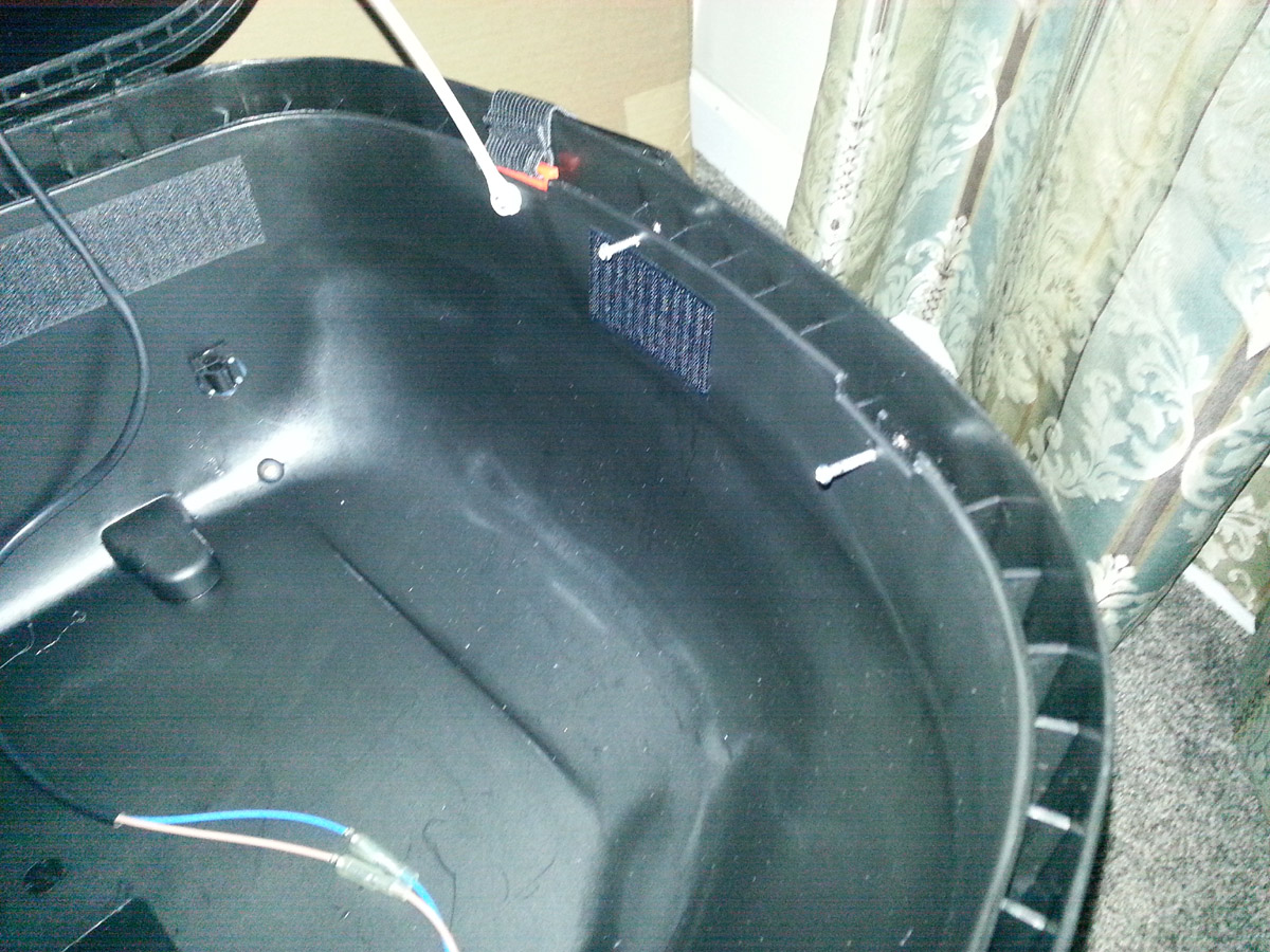
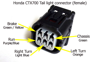
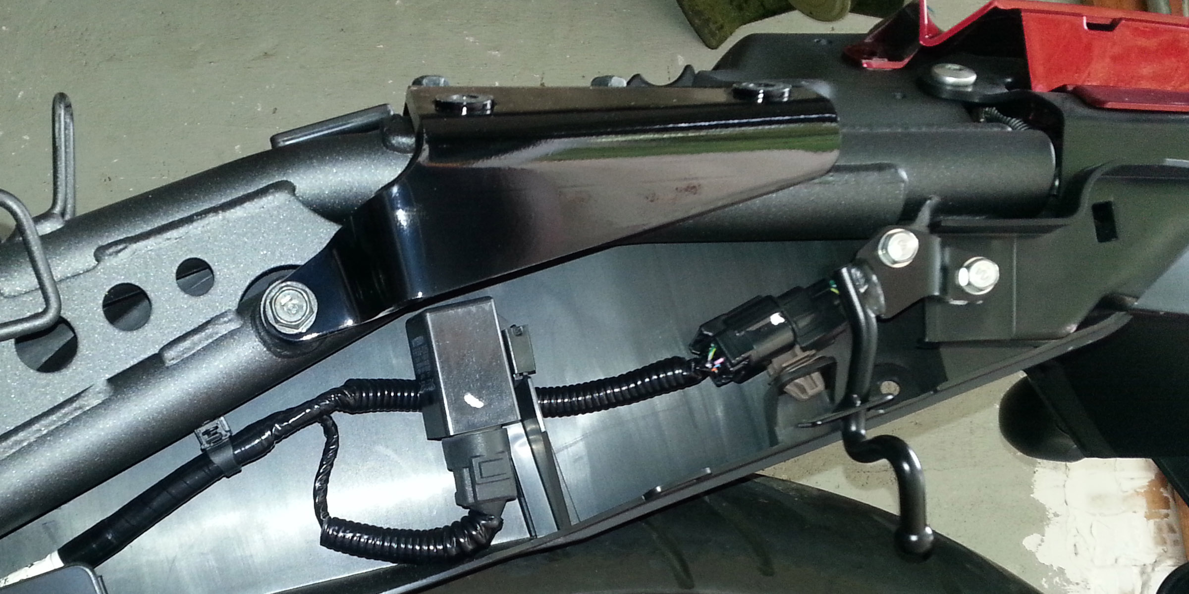
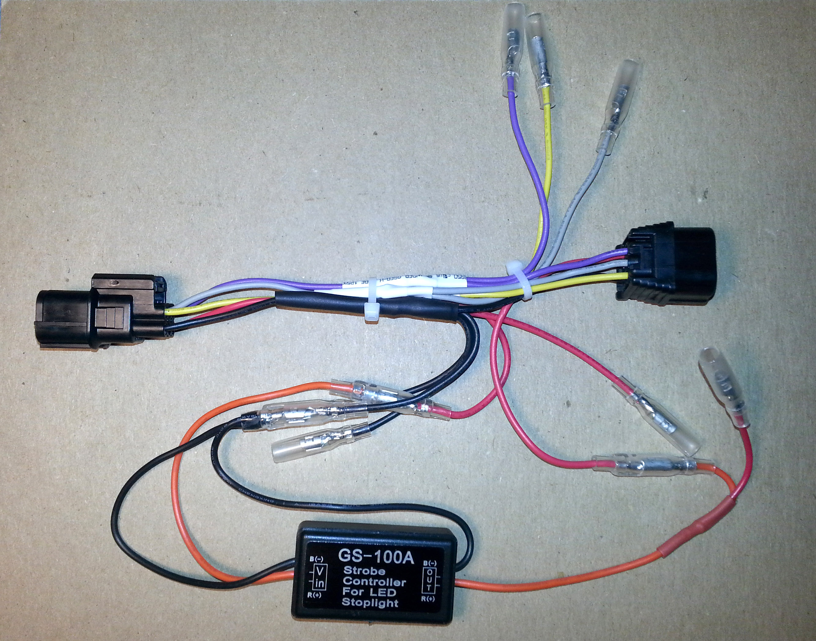
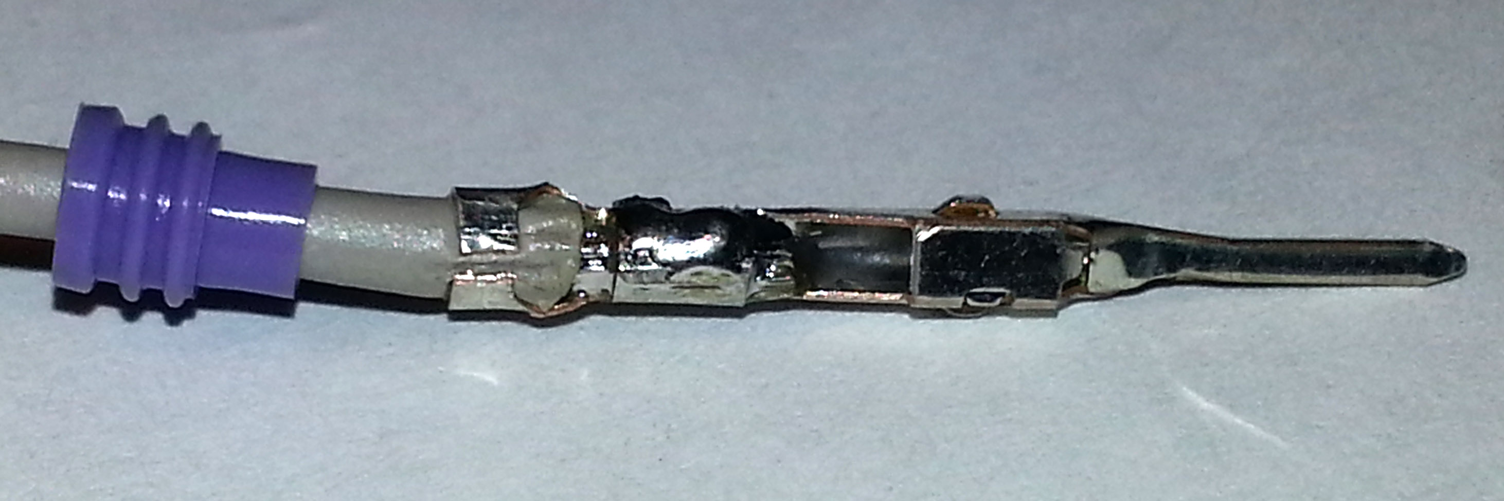
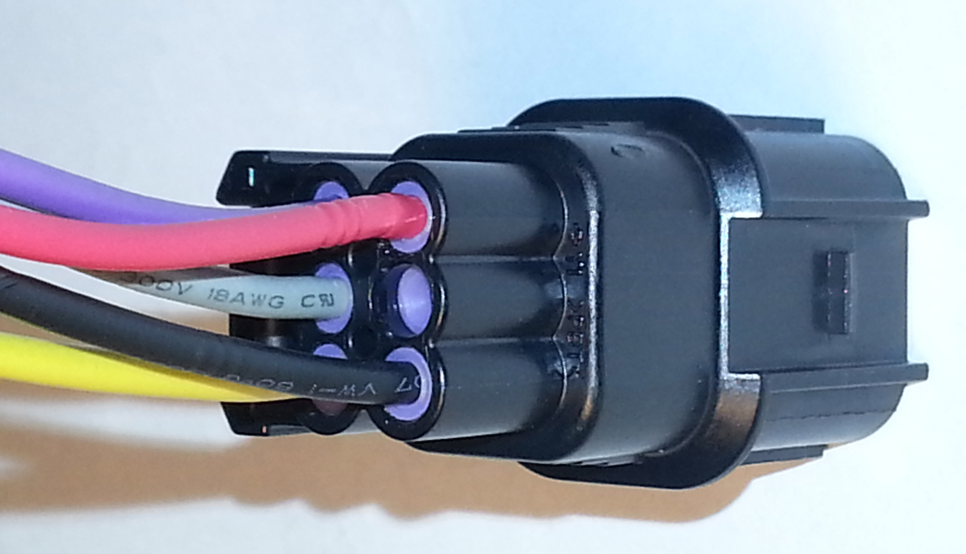
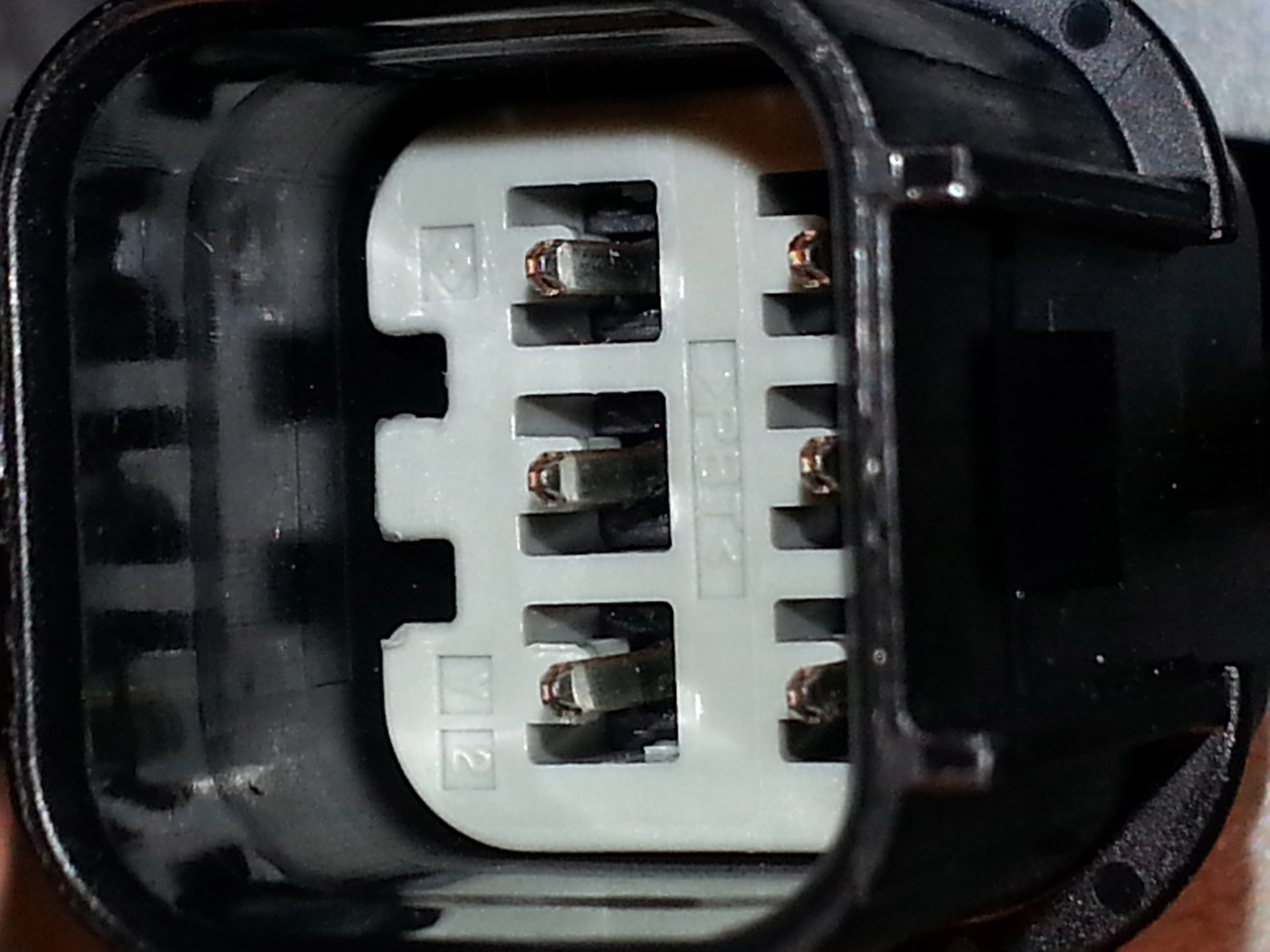
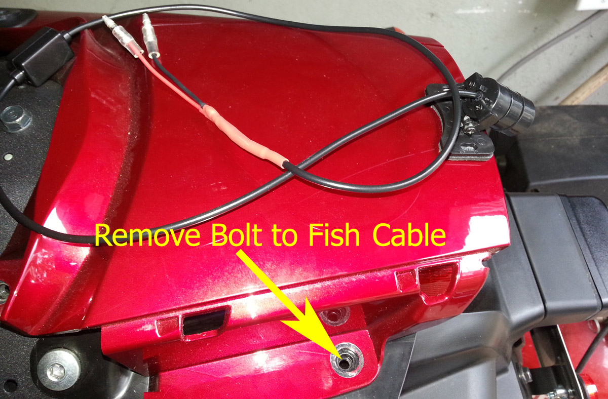
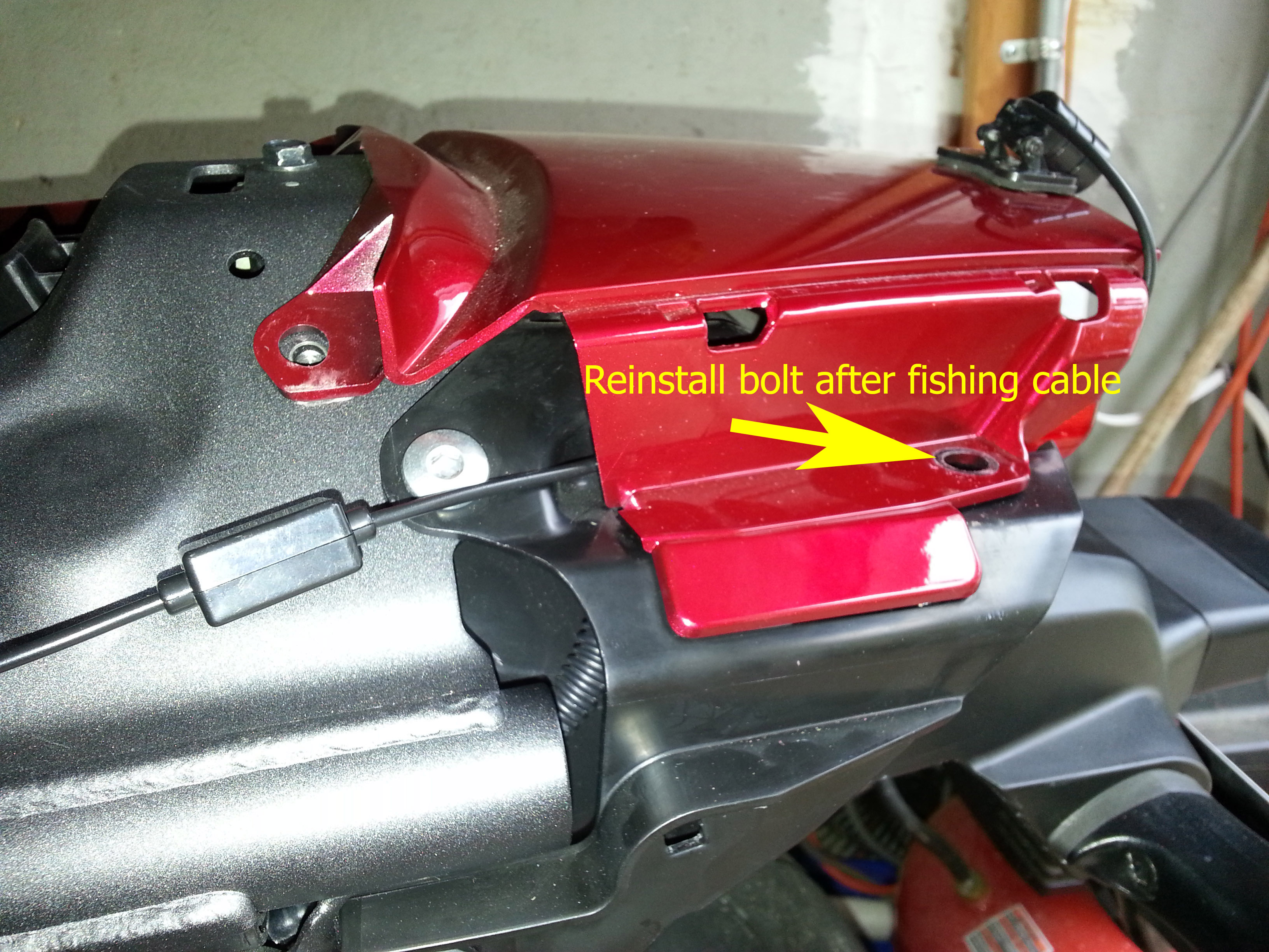
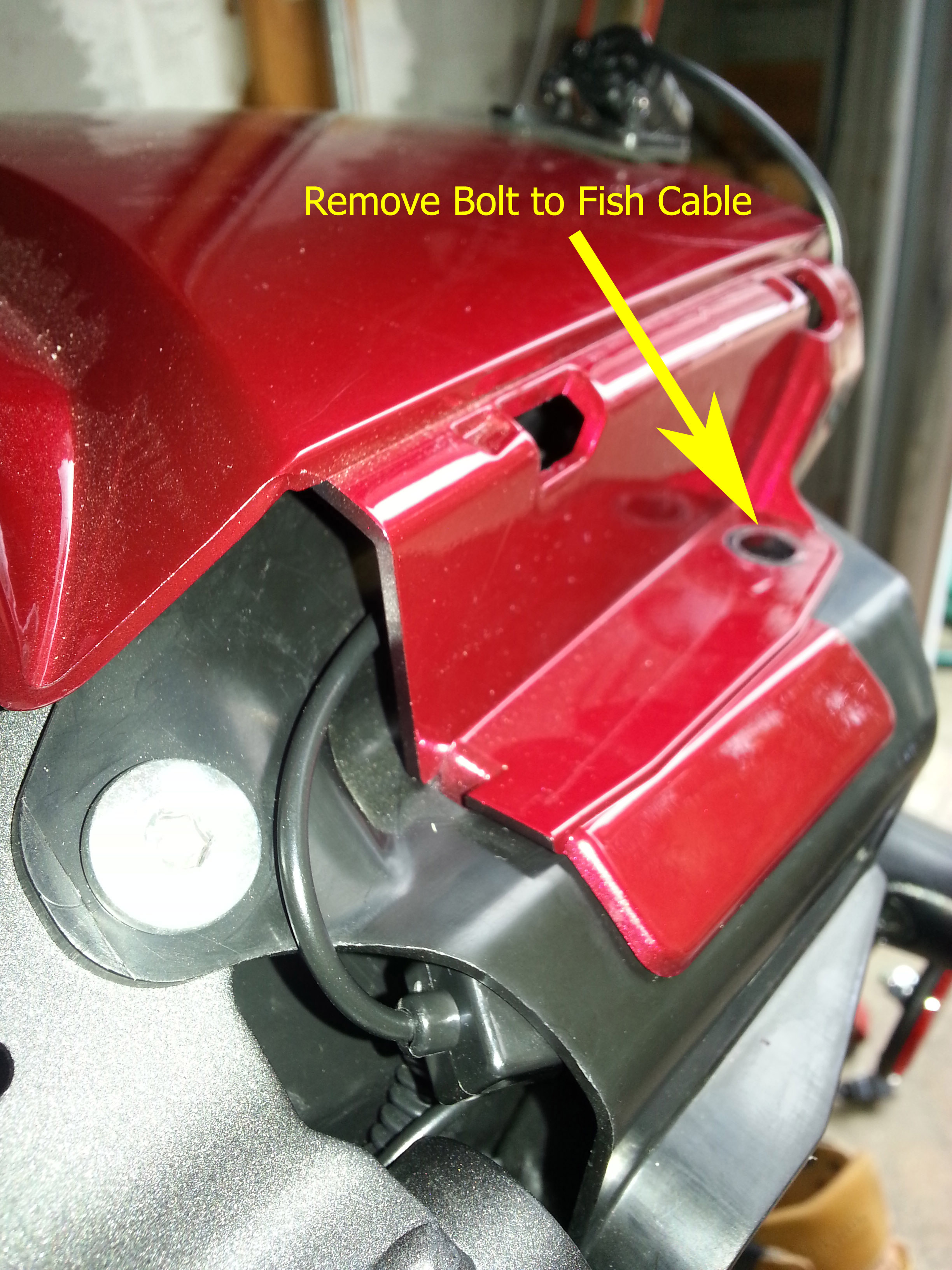
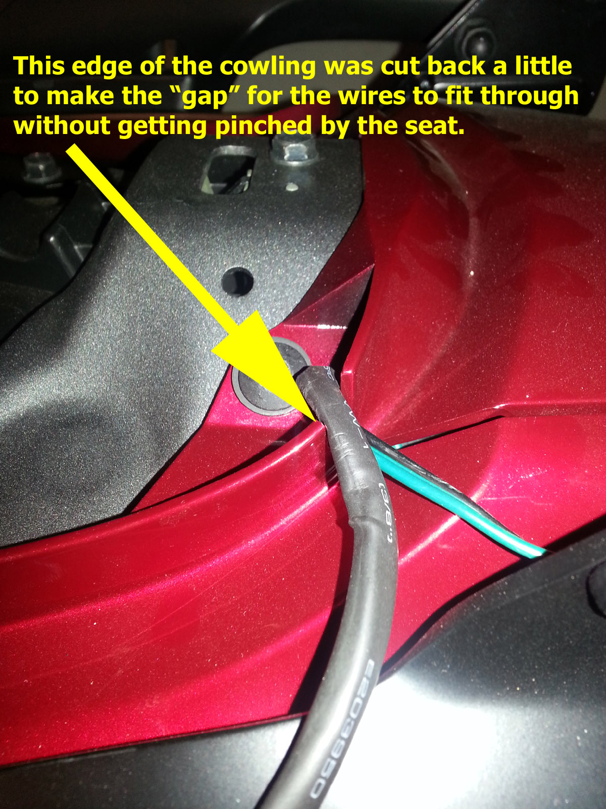
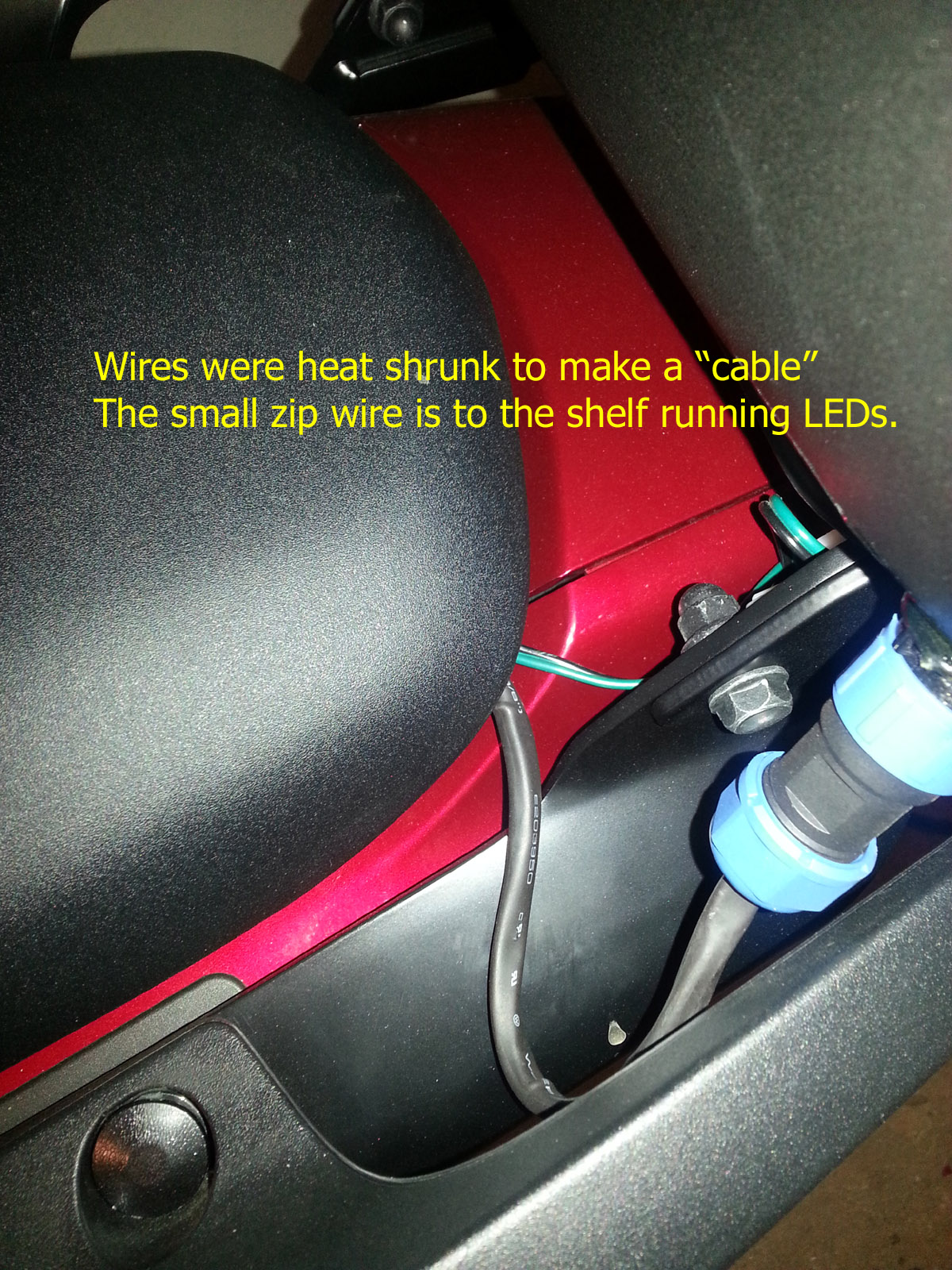
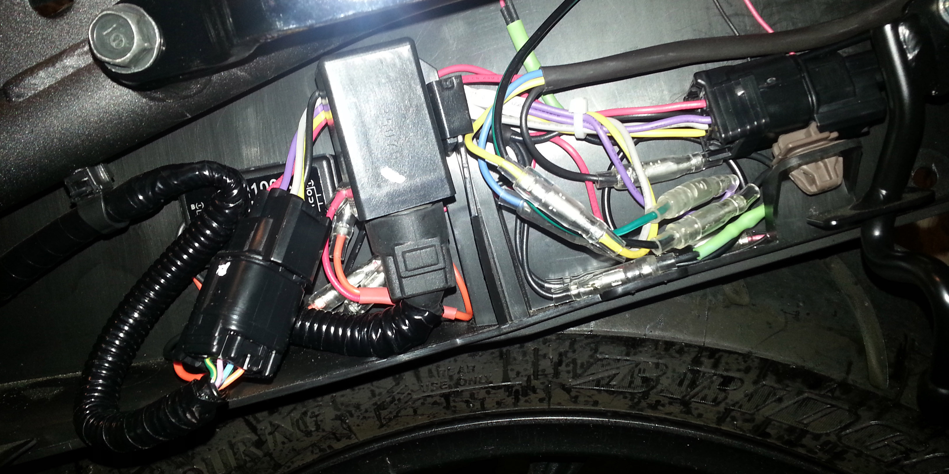
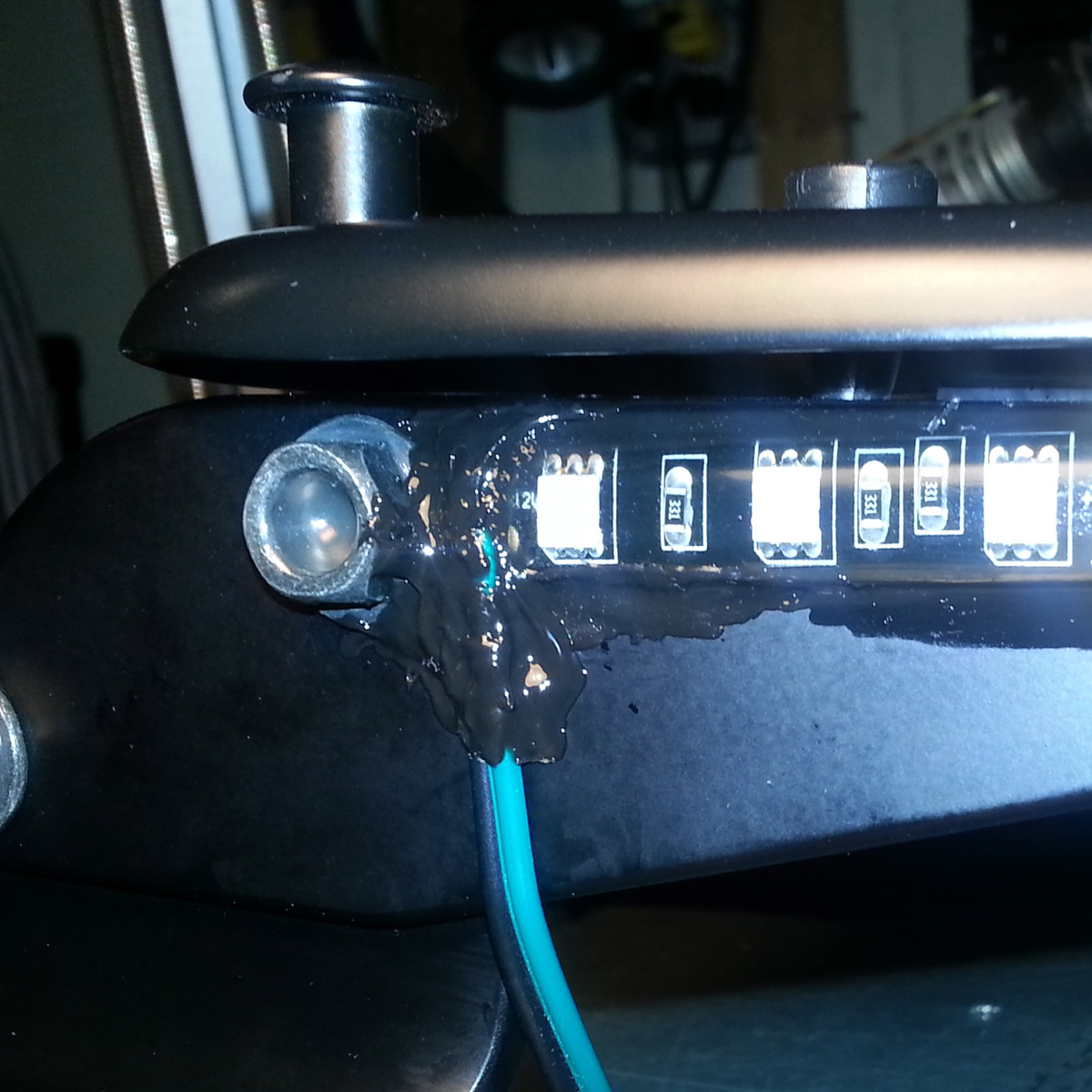
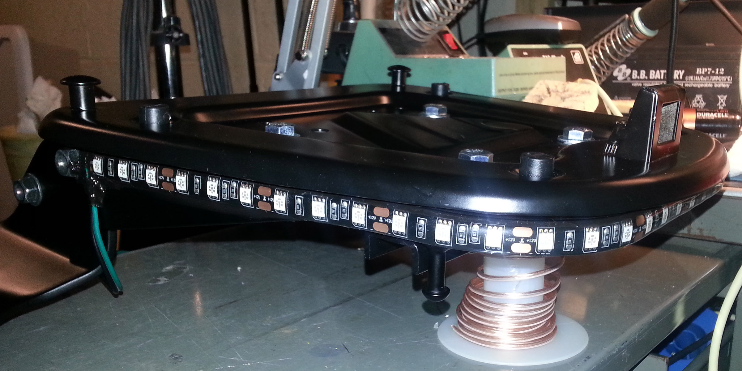
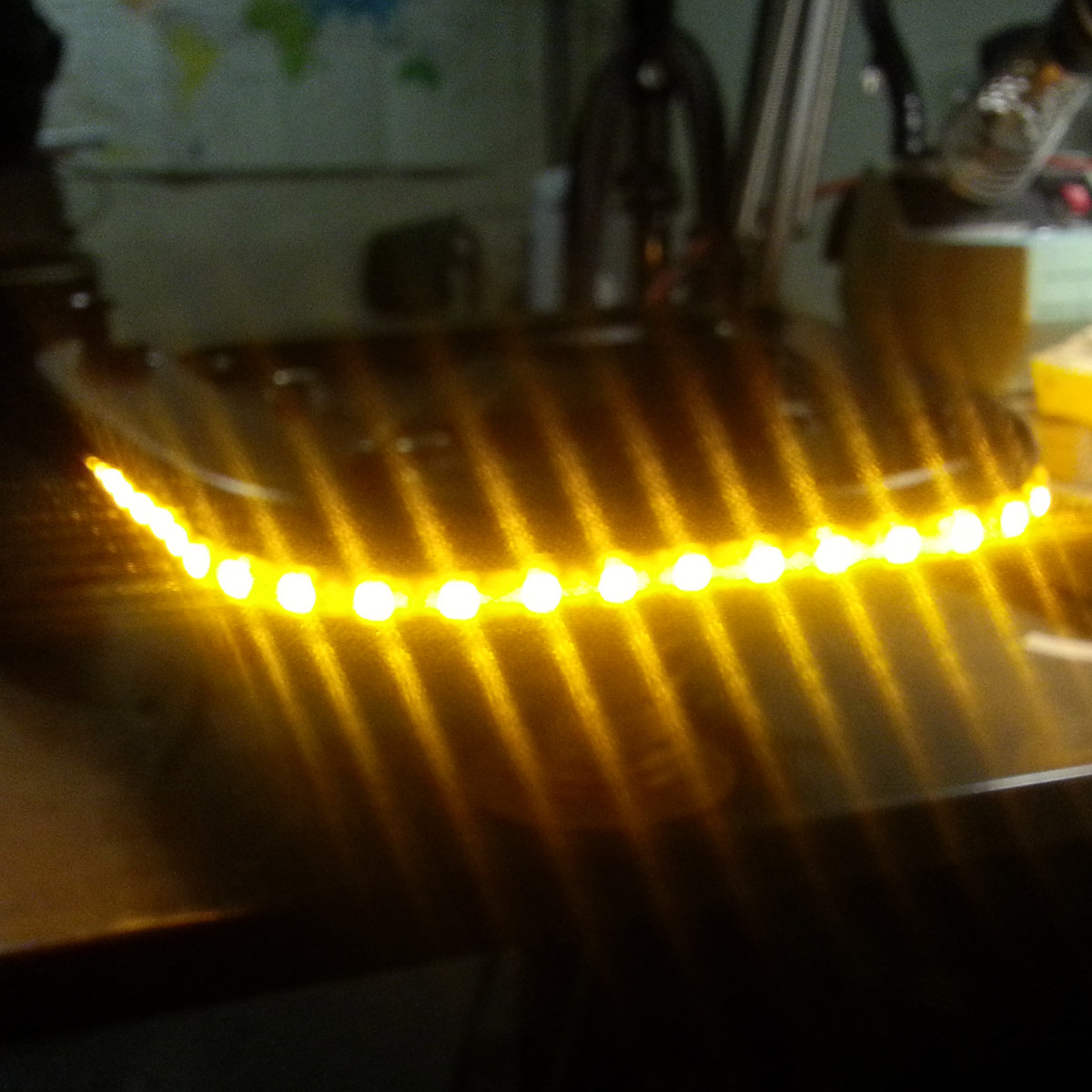
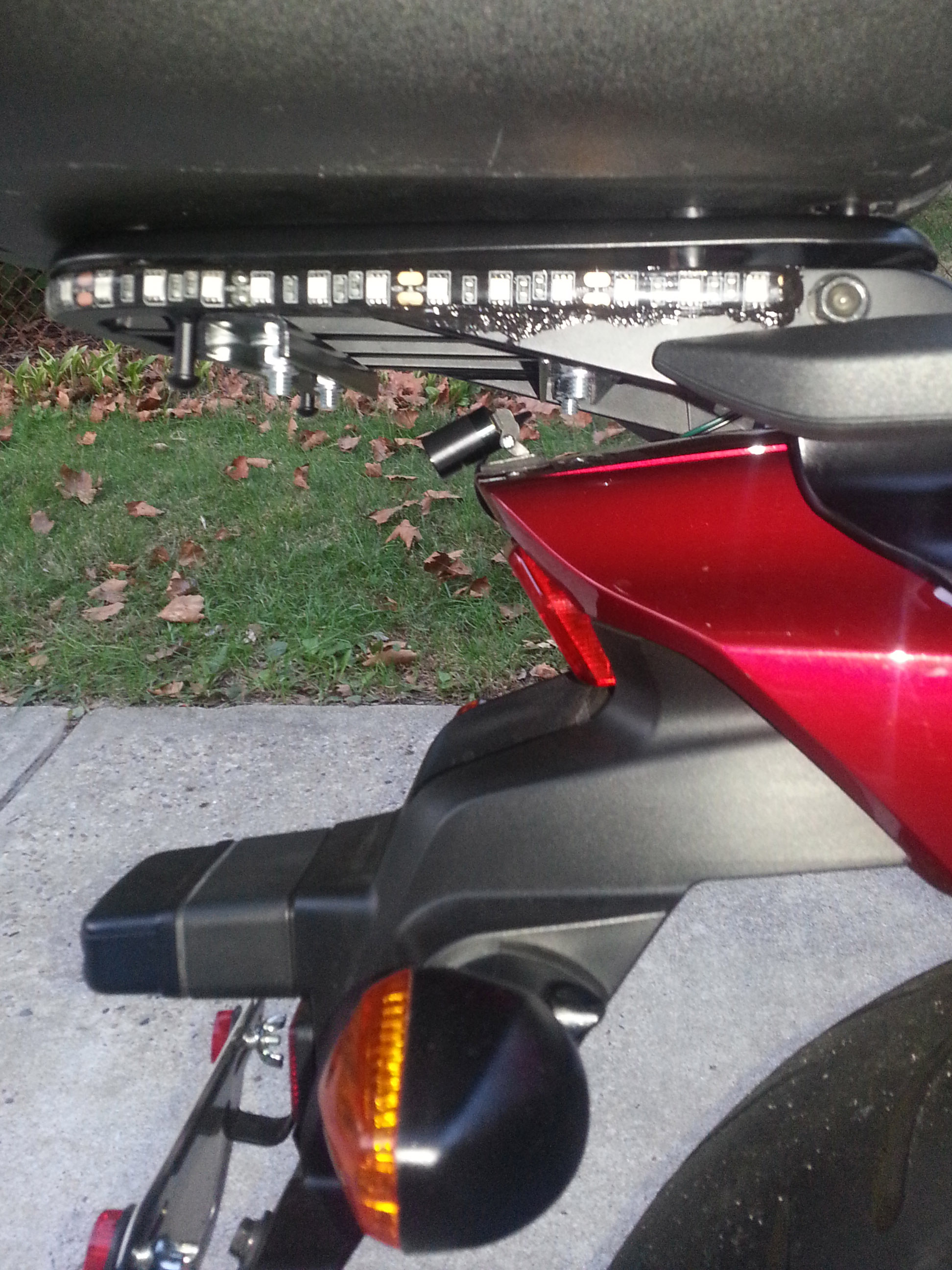
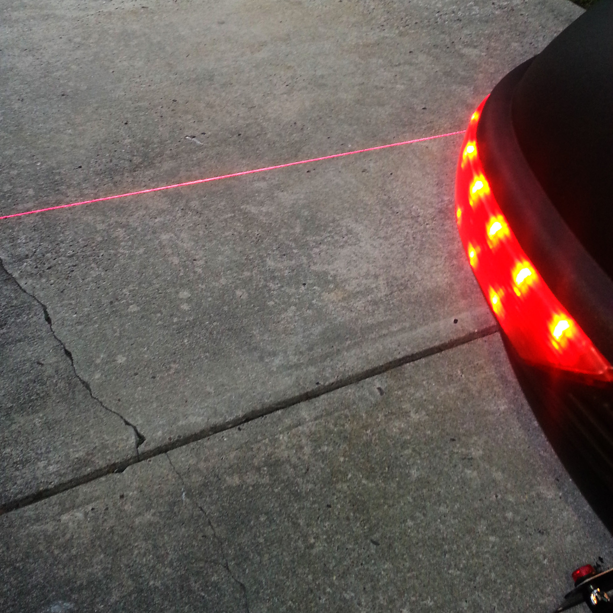
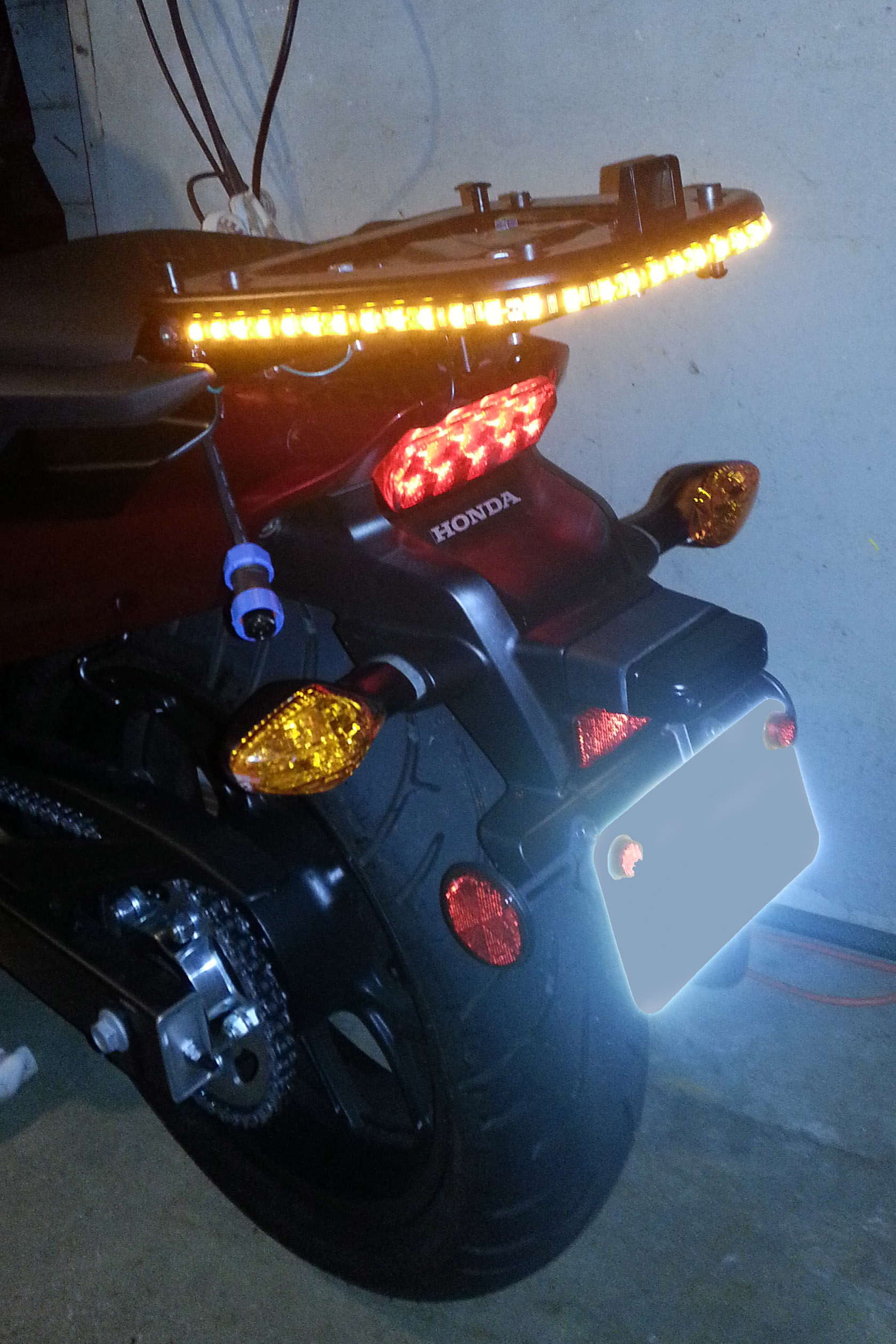
I had installed the rear carrier a few weeks before ordering the Bestem 929 because I had yet to make up my mind to get the Bestem.. Accessing the connector to tap into the brake light power means removing the left sde plastic cowling. Yep you guessed it. The backrest brackets that hold the rear carrier need to come off to get the cowling off! I ended up removing the rear carrier by unbolting the passenger hadles and the backrest brackets. That way BOTH the brackets AND the rear carrier shelf came off the bike as one unit. Instead of just making brake connections I figgured I'd go the full monty and break out ALL of the electrical signals to the tail light adding turn signals and running LEDs along with the brake light.. Click HERE to jump to the installation
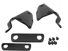
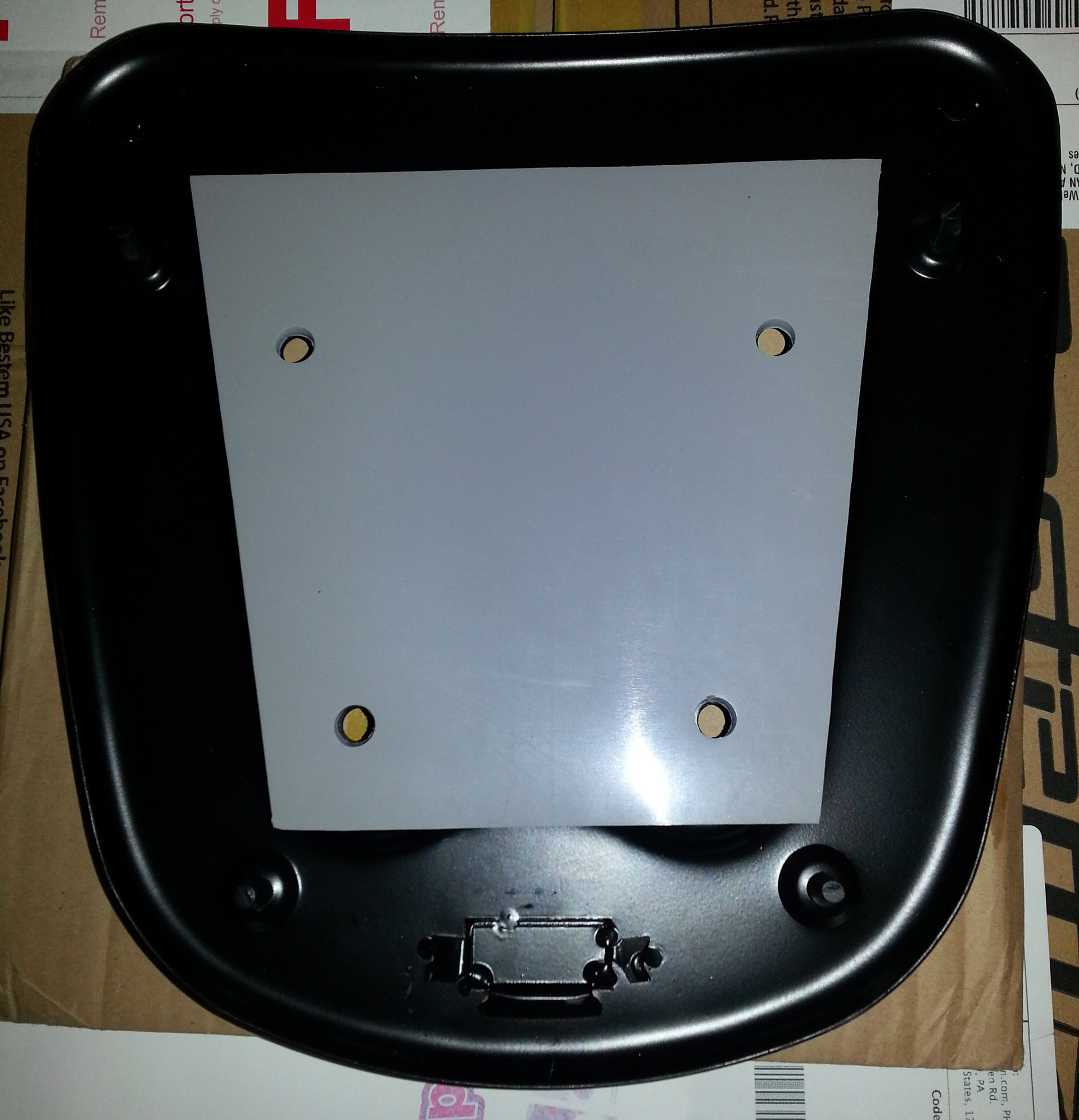
P/N 08L72-MJF-A00
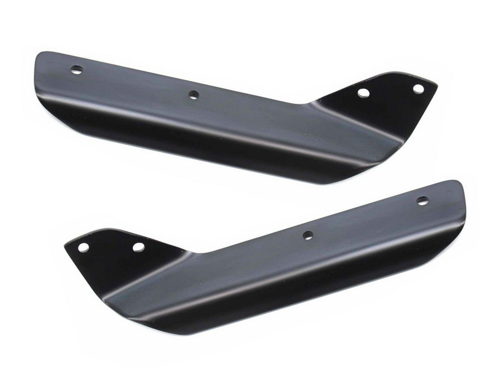
P/N 08R71-MJF-A00ZP
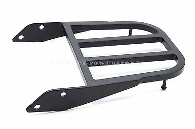
P/N 08L70-MJF-A00ZP
 |
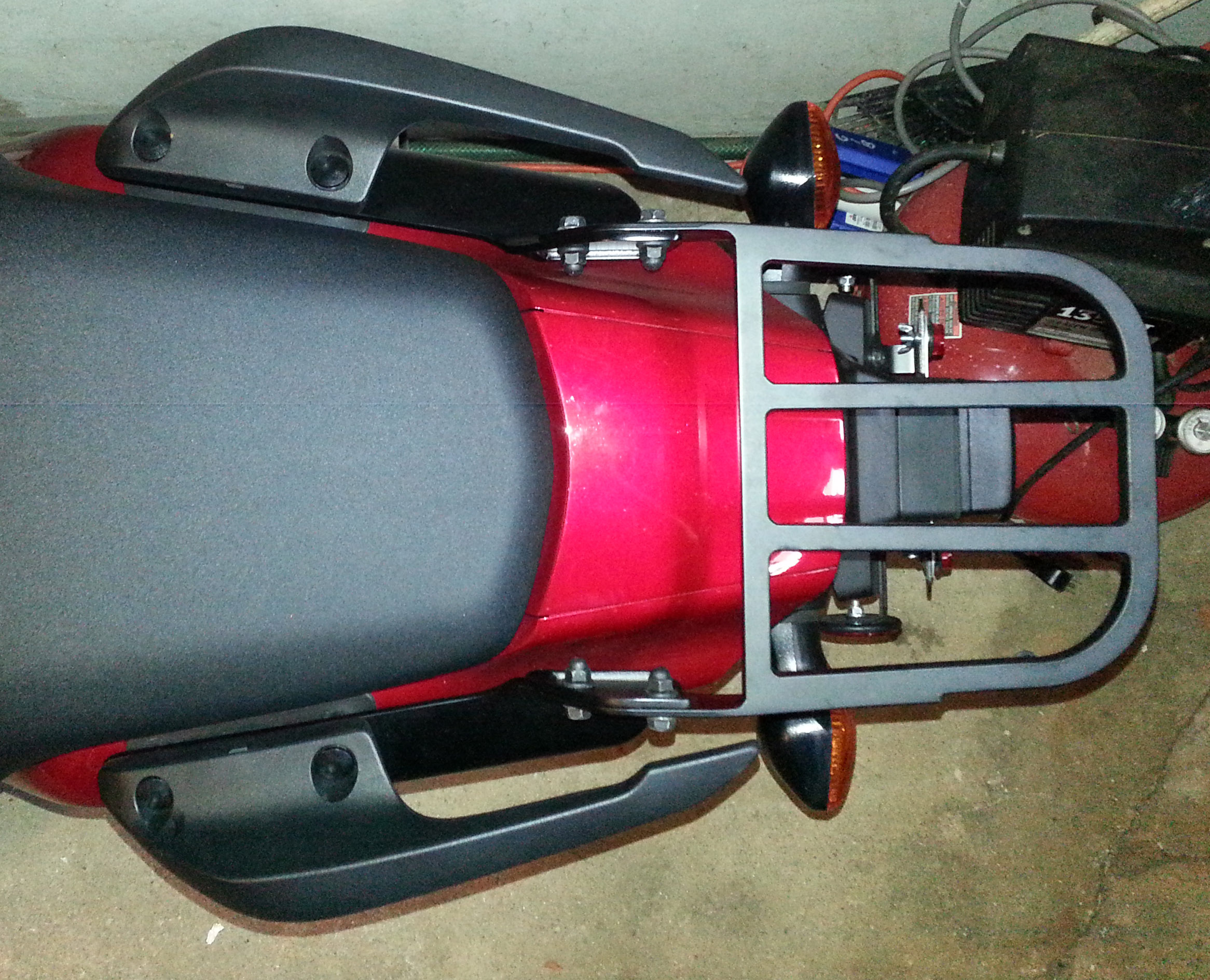 |
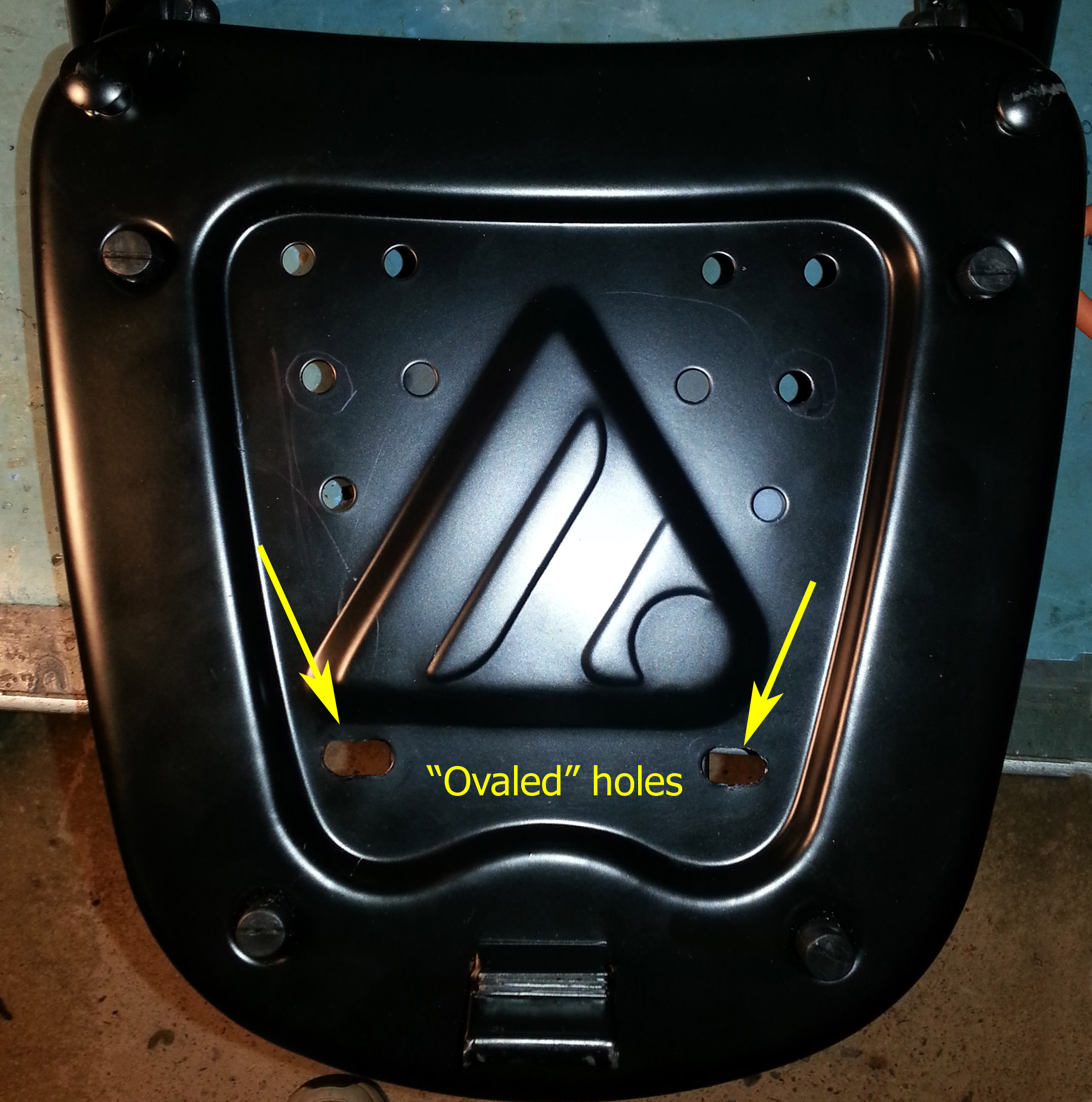
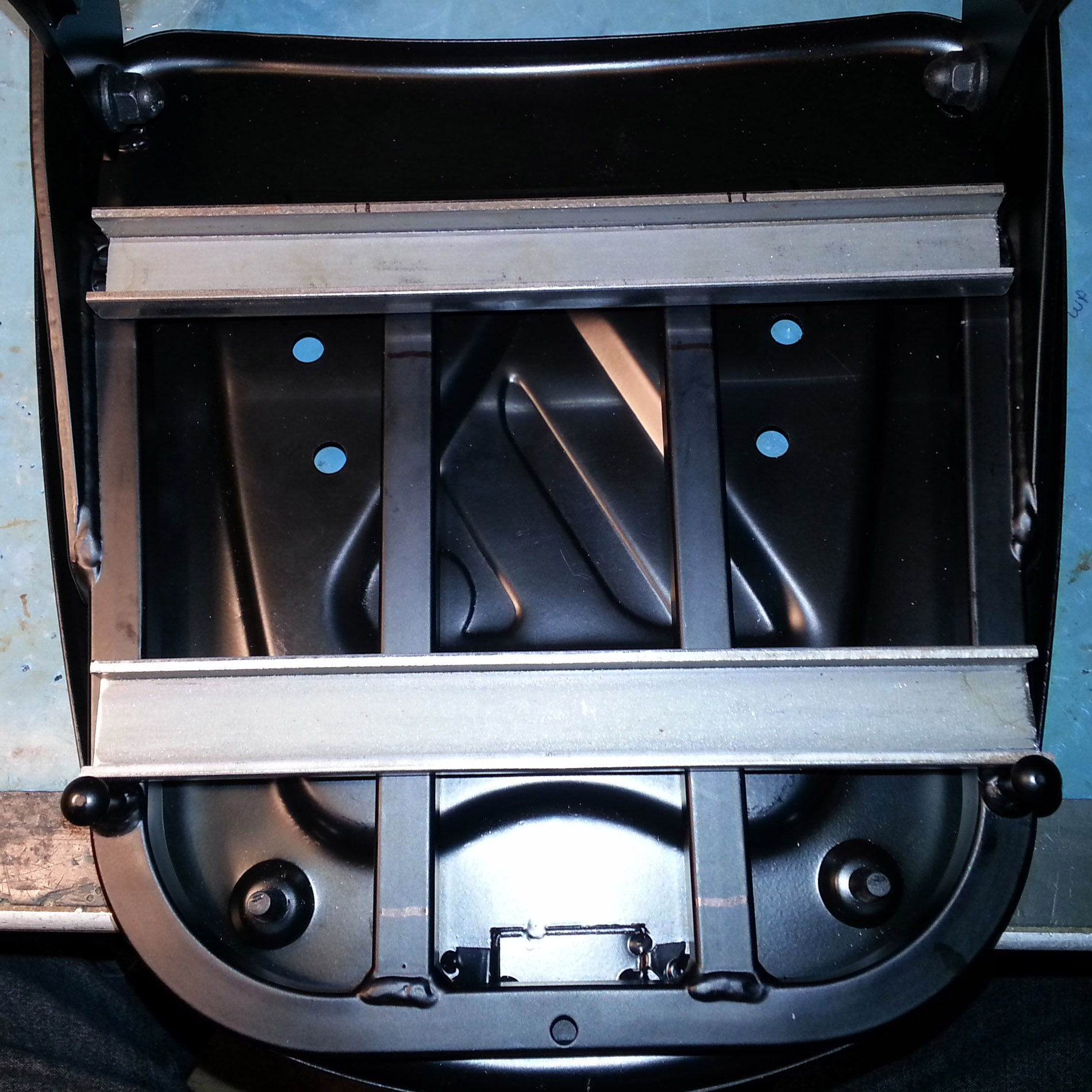
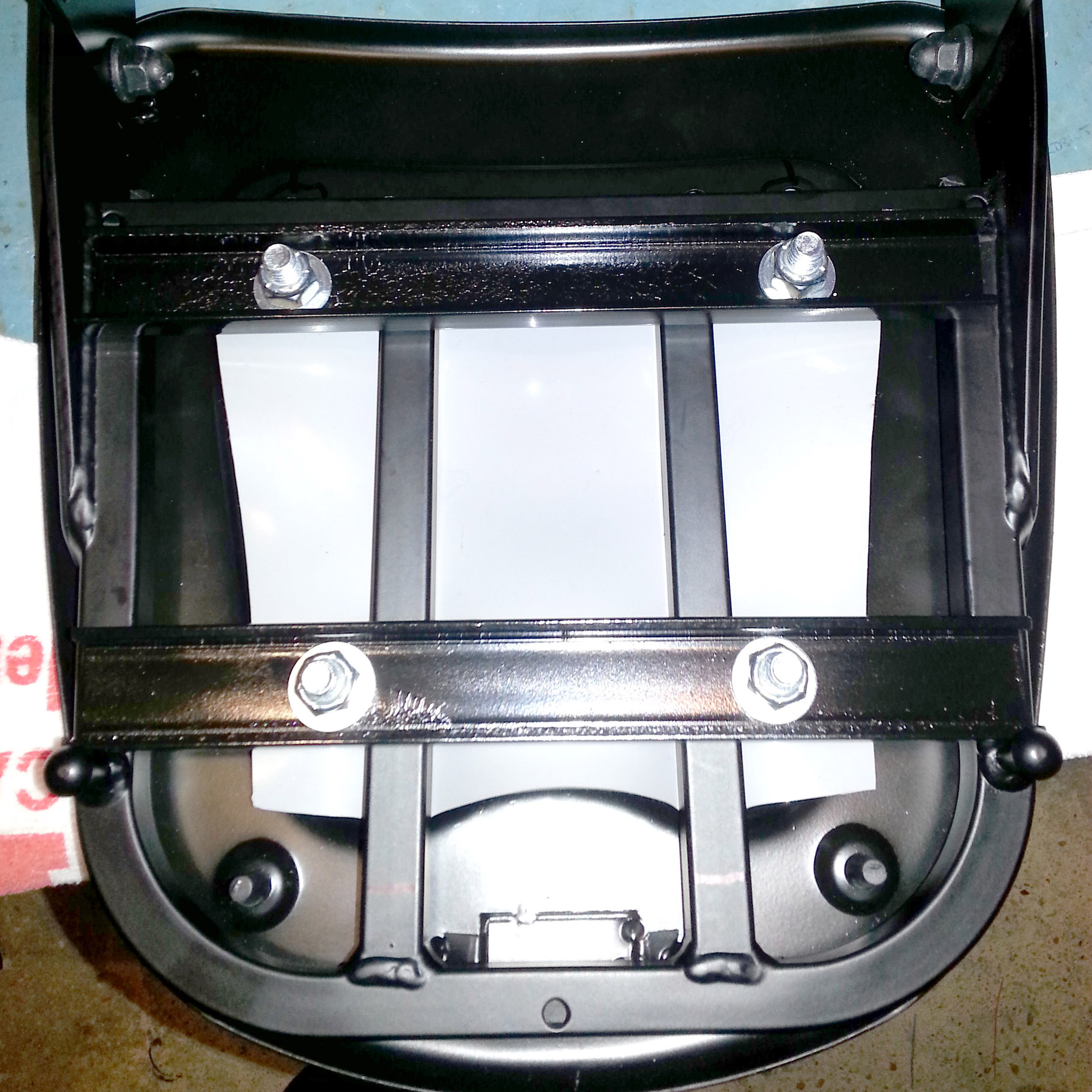
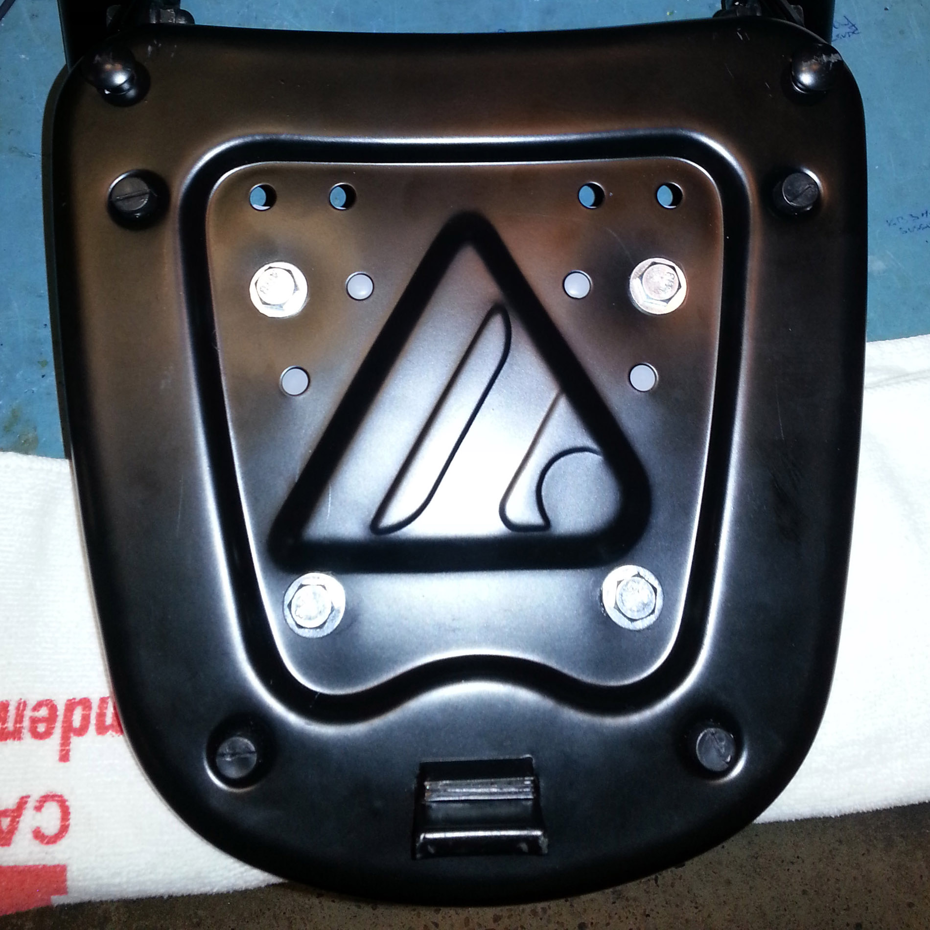
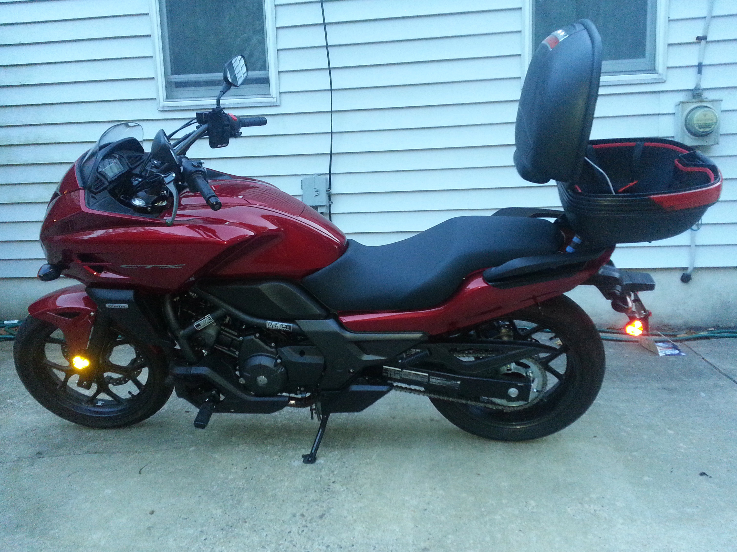
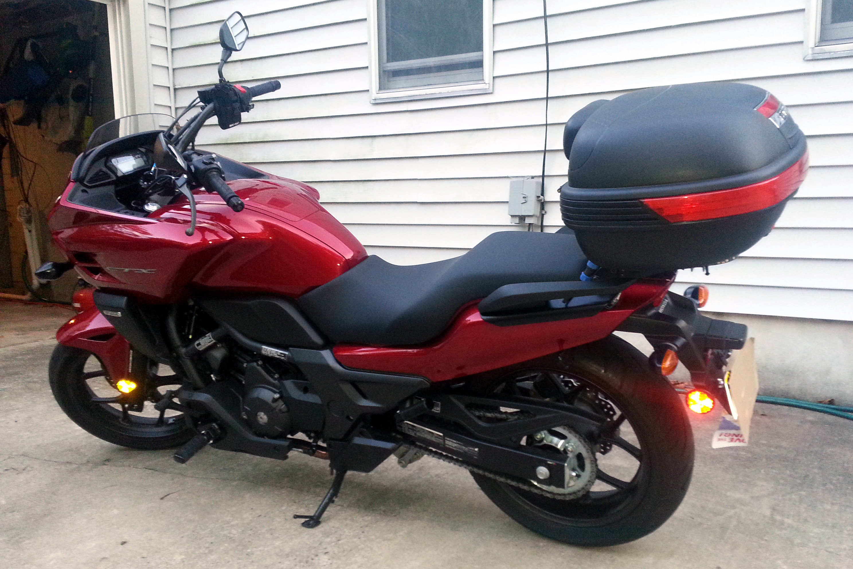
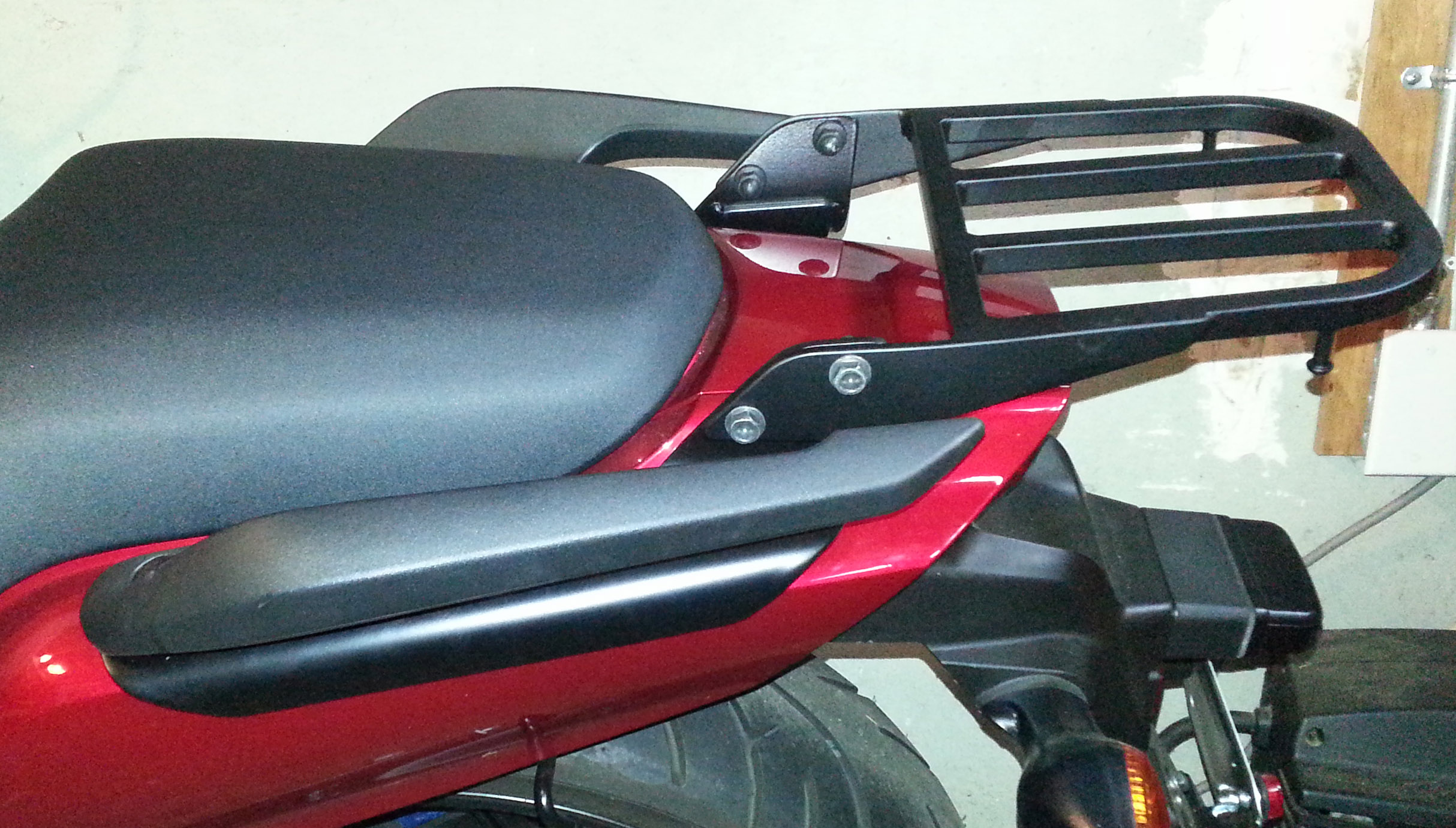
Here is what the OEM rear carrrier looks like when installed per Honda's instructions. |
This isn't the best look down view, but you get the idea. |