INTRODUCTION
The objective of this study was to use amateur radio station equipment to quantify a satellite's orbital velocity based on the observed Doppler frequency shift on the satellite radio beacon signal.
THE SATELLITE
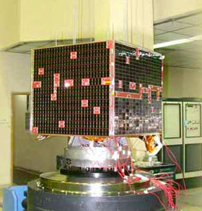
VO-52 (also known as HAMSAT India)1 was launched on 5 May 2005 to provide emergency communications and to stimulate interest in the scientific and technical aspects of satellite communication. VO-52 is is a low earth orbit satellite with a mean orbital altitude of 619.35 km and an orbital period of 97.23 minutes. It carries an inverting Mode U/V linear transponder and a continuous CW beacon transmitter with an output power of one watt on 145.86 MHz.
THE RECEIVING STATION
The receiving station consisted of an Elecraft XV-144 transverter and a FlexRadio 1500 software defined radio. The transmission lines consisted of 14 m lengths of Belden 8214 RG-8/U foam coaxial cable with 1.6 dB attenuation. The station was located in Citrus Heights, California, at an elevation of 32 m in the Sacramento Valley.
The station had two omnidirectional antennas:
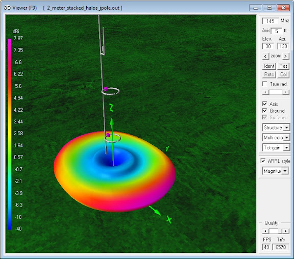
- a pair of stacked horizontally polarized halo antennas with 7.9 dBi gain; and,
- a lower gain Arrow OSJ 146/440 J-pole antenna.
The stacked halo antennas had superior gain, directivity and rejection of vertically polarized noise for reception at low elevation angles. The J-pole antenna was not an ideal antenna for overhead satellite reception, but offered better sensitivity than the halo antennas for signals from higher elevation angles.
OBSERVATION AND DATA
A near overhead pass of this satellite from 0259 to 0312 UTC on 9 SEP 2012 was selected for observation. During the entire satellite pass a video recording was made of the receiver panadapter frequency display with the concurrent satellite elevation, distance and footprint map as calculated by the Satscape program.2 The halo antennas were used for reception near the beginning and end of the pass, and the J-pole antenna was selected when signal strength decreased during the higher elevation angles of the pass.
Here are the measured frequencies at acquisition of signal (AOS), nearest approach and loss of signal (LOS):
| Data |
Time UTC | Elevation | Frequency Hz |
|---|---|---|---|
| AOS | 0302 | 25° | 145,864,400 |
| Nearest approach | 0305 | 89° | 145,861,450 |
| LOS | 0312 | 0° | 145,858,100 |
DATA ANALYSIS
Due to the absence of Doppler shift at the point of nearest approach, the frequency measured at that time was taken to represent the true transmitter frequency f0.
In classical physics, where the speeds of source and the receiver relative to the medium are lower than the velocity of waves in the medium, the relationship between observed frequency f and emitted frequency f0 is given by:3
 , where
 c is the velocity of waves in the medium
(299,792,458 m/s);
vr is the velocity of the receiver
relative to the medium; positive if the receiver is moving
towards the source; and
vs is the velocity of the source
relative to the medium; positive if the source is moving
away from the receiver.
as the receiver is taken to be stationary the above equation simplifies to:
The calculated velocity vs
represents the linear velocity vector component relative
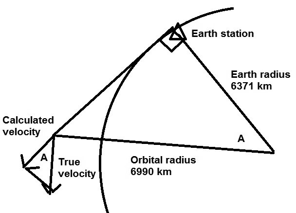
to the receiving station. For orbits that pass
directly over the receiving station, the accompanying
figure demonstrates the calculation of the true orbital
velocity.* At zero elevation angle, the two right
triangles are similar (equal corresponding angles and
proportional sides) and the following ratio holds true
yielding v as the true orbital velocity:
v/vs = 6990/6371
v = vs × 6990/6371
The following form of the equation will calculate the true orbital velocity for any angle of elevation a:
v = vs × (6990/6371) / cos(a)
The frequency measured at loss of signal, 145,858,100 Hz,
yields a calculated true orbital velocity of 7555
m/s. The orbital velocity calculated by dividing the
orbital circumference (43922 km) by the orbital period is
7529 m/s within 1% of the figure derived from the Doppler
frequency shift.
* Oblique passes (those that do not pass directly over
the receiving station) will require analysis of vector
components in three dimensions in order to calculate the
orbital velocity.

VO-52 HAMSAT India

The stacked halo antennas' superior gain, directivity and rejection of vertically polarized noise for reception at low angles

J-pole antenna is not ideal for overhead satellite reception, but offered better sensitivity for signals from higher angles

Vector analysis of satellite velocity
APPENDIX
REFERENCES
- "About HAMSAT", https://www.amsatindia.org/hamsat
- Satscape Program, Hather, S, G7LIU, http://scotthather.weebly.com/satscape.html
- Rosen, Joe; Gothard, Lisa Quinn (2009). Encyclopedia of Physical Science. Infobase Publishing. p. 155. ISBN 0-8160-7011-3., Extract of page 155 Note that the sign of the relative speed in the source (u) is opposite from the sign in the article (υs,r)
- "The Doppler Shift of Radio Satellite Beacons", Miller, M, N8ZYL, http://amateurgeophysics.wordpress.com/earth-orbiting-satellites/the-doppler-shift-of-satellite-radio-beacons/
- "A Close Up of Doppler Shift", Langdon, A, VK3JED, http://www.qsl.net/vk3jed/doppler.html