Multiple HF Antenna Combinations
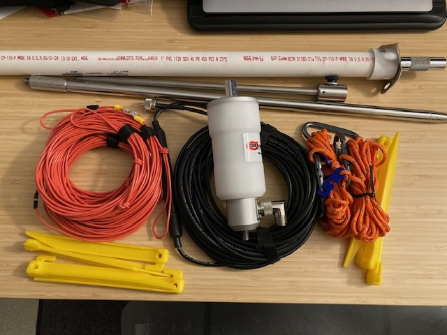
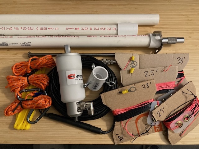
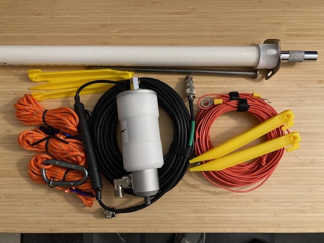
Starting with a small set of high quality commercial antenna components, it is possible to create many different types of antennas setups. This page lists the original two antennas and many additional antenna types put together based on Chameleon Antenna system parts.
While these 17 antenna setups were put together independantly, Chameleon Antenna has just introduced their MPAS-READY Product Guide, sharing multiple antenna systems that can be put together mix-and-match using their products. The antenna combinations listed here utilize just a handful of Chameleon Antenna components integrated with additional low-cost off the shelf internet and hardware store items to fit many different field scenarios and operating conditions.
Starting point:
Chameleon MPAS Lite with TDL add-on kit (hub and top wire) and additional SS-17 telescoping whip.
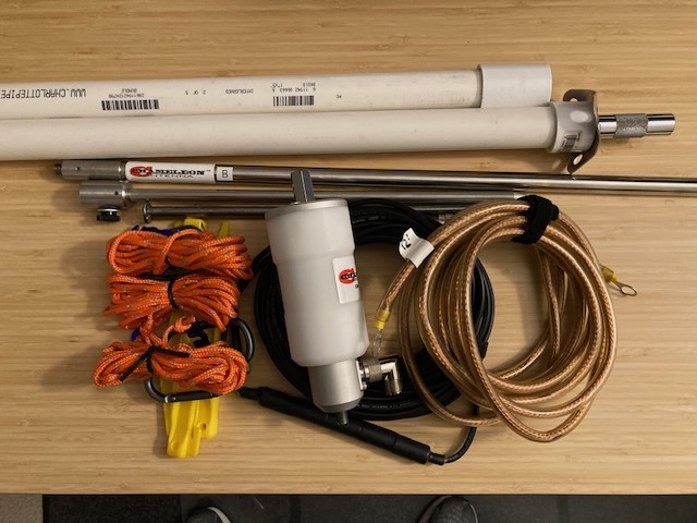
Antenna #1, MPAS Vertical, Ground Mounted (160-6m)
- CHA MPAS Hybrid Mini with right-angle PL-259 to SO-239 adapter
- CHA SS-17 whip (1)
- CHA Ground spike
- Four 25’ red counterpoise/elements w/ 3/8” lugs, stakes
- CHA 50’ RG-58A Coax (PL-259 to PL-259) with SO-239 to BNC-Male adapter
- Small rubber mallet
Set ground spike with mallet, add hybrid with 4 red counterpoise wires at base, attach coax with choke at antenna end*, attach SS-17 to hybrid top and fully extend, roll out counterpoise wires and stake ends, roll out coax and attach to radio. Safety/hazard check system deployment.
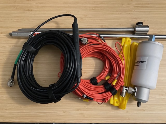
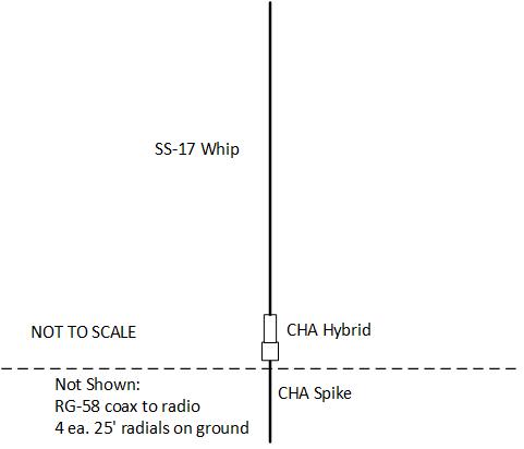
*Prefer to have the ferrite sleeve end of the coax located at the antenna end. This chokes off coax outer conductor current flow and serves to isolate the coaxial cable from the counterpoise of the antenna system. This standard is followed for all of the field antenna setups.
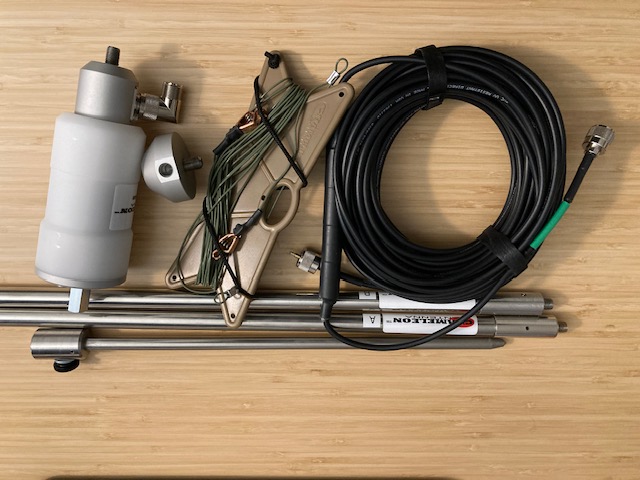
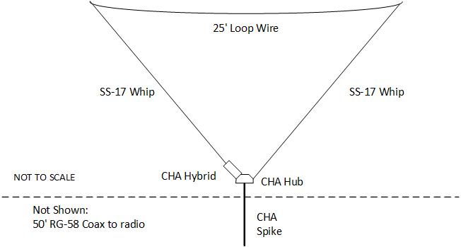
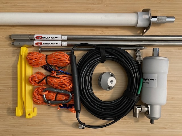
Antenna #2, Tactical Delta Loop, Ground Mounted (80-6m)
- CHA MPAS Hybrid Mini with right-angle PL-259 to SO-239 adapter
- CHA SS-17 whips (2)
- CHA TDL Hub, TDL 25’ top wire on winder
- CHA Ground spike
- CHA 50’ RG-58A Coax (PL-259 to PL-259) with SO-239 to BNC-Male adapter
- Small rubber mallet
Set ground spike with mallet, add hub to spike, add hybrid to hub angle side, attach coax to hybrid with choke at antenna end, attach SS-17 to hybrid top and SS-17 to Hub opposite side, loop-over/clip ends of TDL 25’ top wire to ends of SS-17 elements, extend both SS-17 to full length, roll out coax and attach to radio. Add rope guy to TDL element as needed to prevent free-wheeling in wind. Safety/hazard check system deployment.
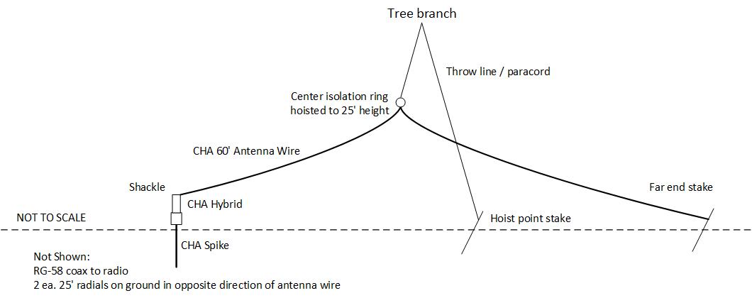
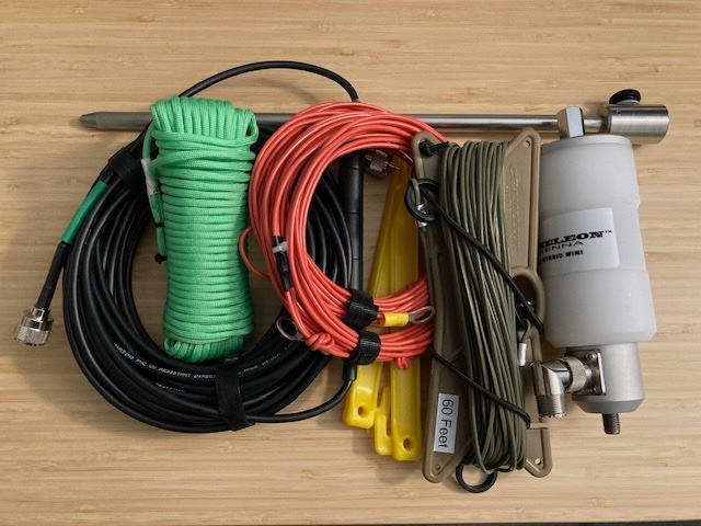
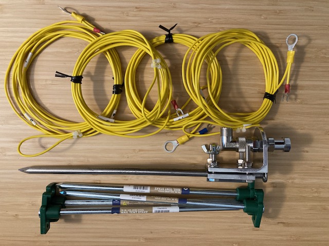
Antenna #3, Inverted V (160-6m, requires ~25’ center support)
- CHA MPAS Hybrid Mini with right-angle PL-259 to SO-239 adapter
- CHA 60' antenna/counterpoise wire on winder
- CHA Ground spike
- Two 25' red counterpoise/elements w/ 3/8" lugs, stakes
- CHA 50' RG-58A Coax (PL-259 to PL-259) with SO-239 to BNC-Male adapter
- Hybrid 3/8-24 accessories, tools, Ox-Gard
- 75' throw line & weight, bag
- Small rubber mallet
Set ground spike with mallet, add hybrid with 2 ea 25’ counterpoise wires at GND end, attach coax to hybrid with choke at antenna end, attach antenna wire with shackle strain relief to hybrid top, extend antenna wire with ring in middle, hoist center support ring to ~25’ height, tension and stake out antenna wire far end, extend and stake counterpoise wires opposite direction of antenna wire (120 deg), roll out coax and attach to radio. Safety/hazard check system deployment.
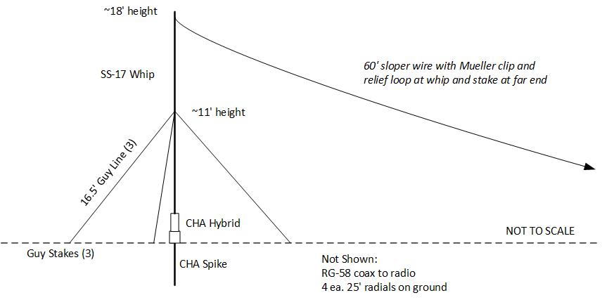
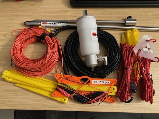
Antenna #4, MPAS Vertical with 60’ Lazy-Sloper wire, Ground Mounted (160-6m)
- CHA MPAS Hybrid Mini with right-angle PL-259 to SO-239 adapter
- CHA SS-17 whip (1)
- CHA Ground spike
- Four 25’ red counterpoise/elements w/ 3/8” lugs, stakes
- 60’ Lazy-Sloper wire with far-end stake
- Universal Guying System (Center & three 16.5’ 1/8” red paracord, stakes)
- Hybrid 3/8-24 accessories, tools, Ox-Gard
- CHA 50’ RG-58A Coax (PL-259 to PL-259) with SO-239 to BNC-Male adapter
- Small rubber mallet
Set ground spike with mallet, add hybrid with 4 red counterpoise wires at base, attach coax to hybrid with choke at antenna end, attach SS-17 and partially extend, add guying system to SS-17, loop over/clip Lazy-Sloper wire to SS-17, fully extend SS-17, set guying system and stake, extend Lazy-Sloper wire and stake end, roll out counterpoise wires and stake ends, roll out coax and attach to radio. Safety/hazard check system deployment.
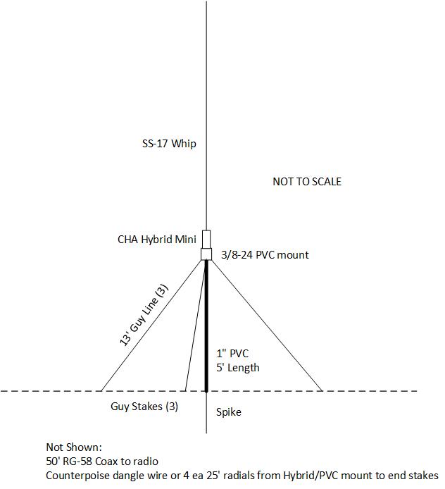
Antenna #5, Elevated MPAS Vertical (160-6m, 10’ raised mount)
- CHA MPAS Hybrid Mini with right-angle PL-259 to SO-239 adapter
- CHA SS-17 whip (1)
- Landscape spike
- Four 25’ red counterpoise/elements w/ 3/8” lugs, stakes
- Two 5’ PVC pipe with coupler and 3/8-24 top mount
- PVC mount guys, 13’ 1/8” orange paracord, 3 each with carabiners and adjusters, stakes
- CHA 50’ RG-58A Coax (PL-259 to PL-259) with SO-239 to BNC-Male adapter
- Small rubber mallet
Assemble MPAS vertical with hybrid, SS-17 to hybrid top, red counterpoise wires to hybrid base, hybrid base to PVC 3/8-24 top mount, pre-assemble PVC mount guys onto 3/8-24 top mount guy points, attach coax to hybrid with choke at antenna end, assemble PVC pipe and couplers, set base spike with mallet, extend SS-17, raise assembly with PVC pipe into position over base spike, extend guy ropes and stake mast vertical, extend and stake counterpoise/radials, fasten coax to mast or wrap a turn or two around mast, roll out coax and attach to radio. Safety/hazard check system deployment.
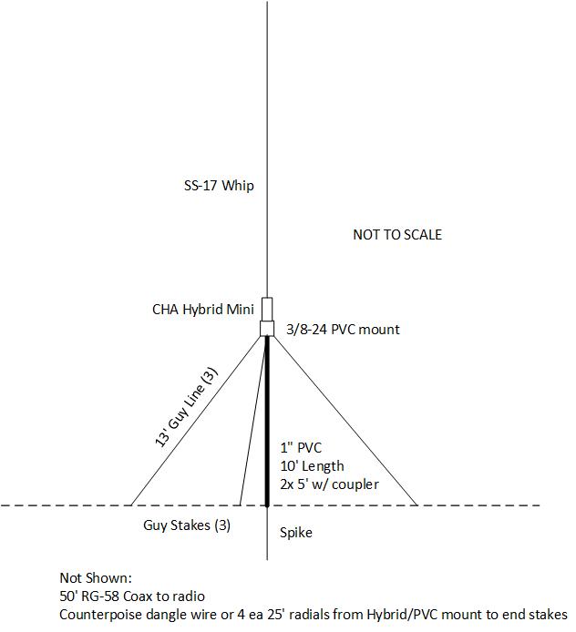
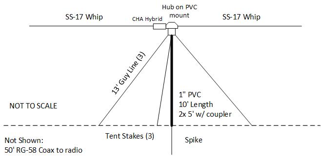
Antenna #6, Elevated MPAS Vertical (160-6m, 5’ raised mount)
- CHA MPAS Hybrid Mini with right-angle PL-259 to SO-239 adapter
- CHA SS-17 whip (1)
- CHA Ground spike or landscape spike
- Four 25’ red counterpoise/elements w/ 3/8” lugs, stakes
- One 5’ PVC pipe with coupler and 3/8-24 top mount
- PVC mount guys, 13’ 1/8” orange paracord, 3 each with carabiners and adjusters, stakes
- CHA 50’ RG-58A Coax (PL-259 to PL-259) with SO-239 to BNC-Male adapter
- Small rubber mallet
Assemble MPAS vertical with hybrid, SS-17, red counterpoise wires at hybrid bottom, pre-assemble PVC mount guys onto 3/8-24 top mount guy points, attach coax to hybrid with choke at antenna end, assemble PVC pipe and top PVC mount, set base spike with mallet, extend SS-17, raise assembly with PVC pipe into position over base spike, extend guy ropes and stake mast vertical, extend and stake counterpoise/radials, fasten coax to mast or wrap one turn around mast, roll out coax and attach to radio. Safety/hazard check system deployment.

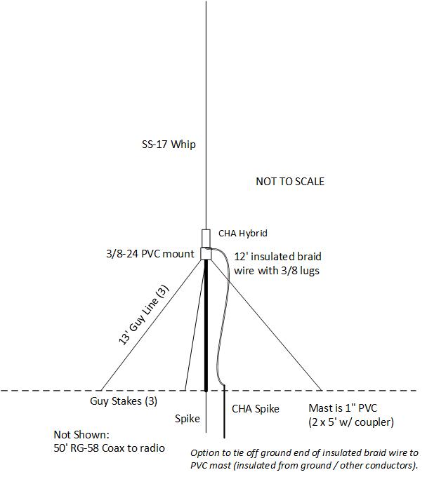
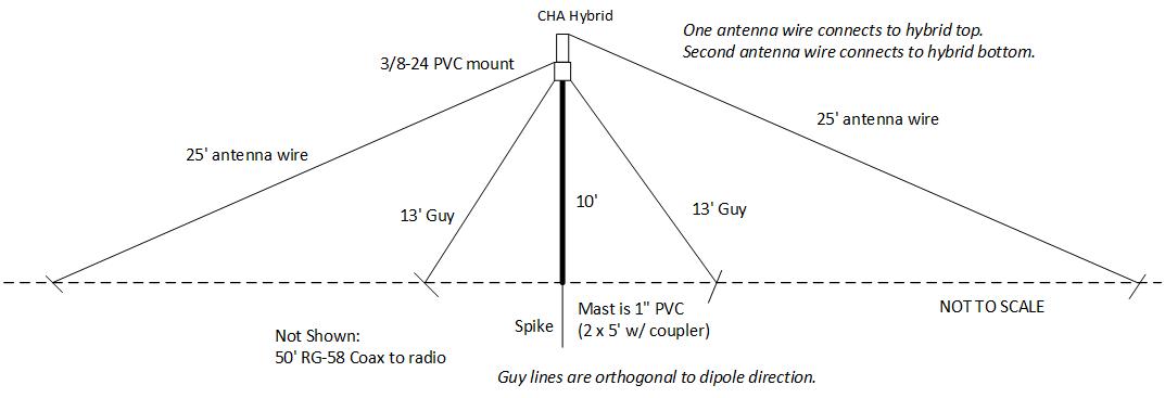
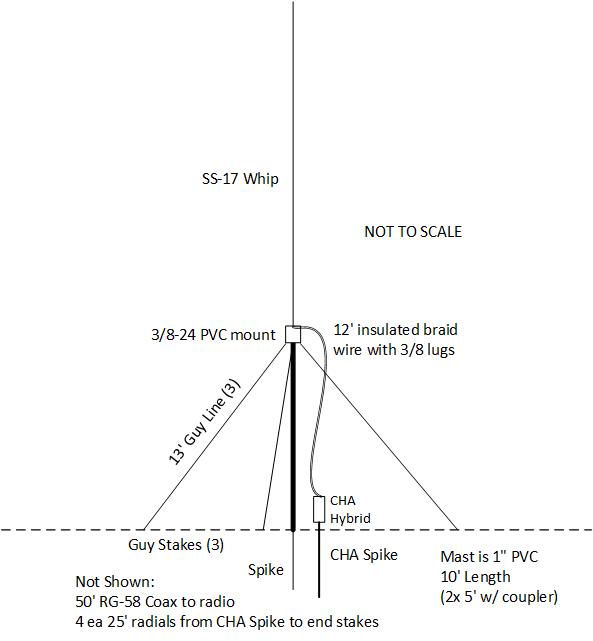
Antenna #7, Elevated MPAS Off Center Fed Dipole (80-6m, 10’ raised mount)
- CHA MPAS Hybrid Mini with right-angle PL-259 to SO-239 adapter
- CHA SS-17 whip (1)
- CHA Ground spike
- Landscape spike
- 12’ plastic covered braid wire w/ 3/8” lugs
- Two 5’ PVC pipe with coupler and 3/8-24 top mount
- PVC mount guys, 13’ 1/8” orange paracord, 3 each with carabiners and adjusters, stakes
- CHA 50’ RG-58A Coax (PL-259 to PL-259) with SO-239 to BNC-Male adapter
- Small rubber mallet
Assemble MPAS vertical with hybrid, SS-17 to hybrid top, plastic covered braid lug to hybrid base, hybrid base to PVC 3/8-24 top mount, pre-assemble PVC mount guys onto 3/8-24 top mount guy points, attach coax to hybrid with choke at antenna end, assemble PVC pipe and couplers, set base landscape spike with mallet, set CHA ground spike 12” from base spike, extend SS-17, raise assembly with PVC pipe into position over base landscape spike, extend guy ropes and stake mast vertical, connect bottom end of plastic covered braid lug to CHA ground spike ground connection, route coax from hybrid away from mast (follow guy wire down), roll out coax and attach to radio. Safety/hazard check system deployment.

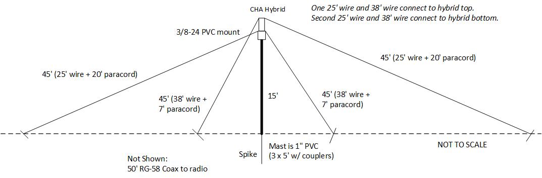
Antenna #8, NVIS Crossed Dipole (160-6m, 15’ self-supported raised mount)
- CHA MPAS Hybrid Mini with right-angle PL-259 to SO-239 adapter
- DIY NVIS antenna dipole wires (25’ and 38’ dipole wire sets and guy ends, stakes)
- Landscape spike
- Three 5’ PVC pipe with coupler and 3/8-24 top mount
- PVC coupler mid-mount guy support at 10’ with guys, 13’ 1/8” orange paracord, 3 each with carabiners and adjusters, stakes
- CHA 50’ RG-58A Coax (PL-259 to PL-259) with SO-239 to BNC-Male adapter
- Small rubber mallet
Assemble PVC top mount with hybrid and dipole wires (1 ea 25’ and 38’ wires at hybrid top and 1 ea 25’ and 38’ wires at hybrid bottom, pre-assemble PVC mount guys onto 10’ mid mount/coupler guy points, attach coax to hybrid with choke at antenna end, assemble PVC pipe and couplers, set base spike with mallet, raise assembly with PVC pipe into vertical position over base spike, detangle coax / dipole wires, extend 10’ coupler mount guy ropes and stake mast vertical, extend antenna wires and stake rope ends in crossed dipole orientation, fasten coax to mast or wrap coax around pole length a turn or two, roll out coax and attach to radio. Safety/hazard check system deployment.
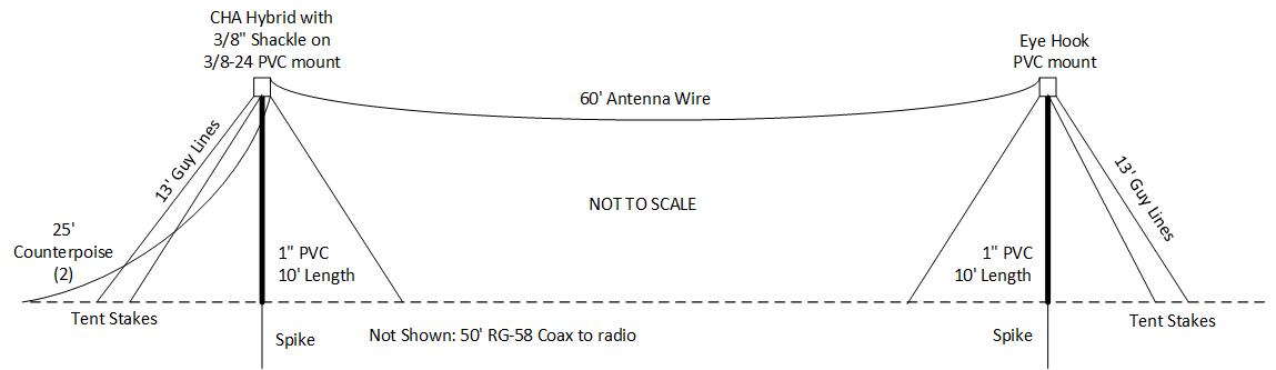
Antenna #9, NVIS 60’ Long Wire (160-6m, 10’ raised ends)
- CHA MPAS Hybrid Mini with right-angle PL-259 to SO-239 adapter
- CHA 60’ NVIS antenna wire
- Two 25’ red counterpoise/elements w/ 3/8” lugs, stakes
- Two landscape spikes
- Four 5’ PVC pipe with two mast in-line couplers
- PVC 3/8-24 top mount (hybrid end) and PVC pulley/eye-hook top mount (far end)
- PVC mast guys, 13’ 1/8” orange paracord, 6 each with carabiners and adjusters, stakes
- Hybrid 3/8-24 accessories, tools, Ox-Gard
- CHA 50’ RG-58A Coax (PL-259 to PL-259) with SO-239 to BNC-Male adapter
- Small rubber mallet
Assemble PVC top mount with hybrid, 60’ NVIS wire with strain relief shackle at hybrid top end and two 25’ counterpoise at hybrid bottom end, pre-assemble PVC mount guys onto both top mounts, attach coax to hybrid with choke at antenna end, assemble 2 ea 10’ PVC pipe and couplers, set base spikes with mallet at ~65’ apart, raise feed end assembly with PVC pipe into position over base spike, detangle coax / counterpoise wires, extend feed end mount guy ropes and stake mast vertical, add paracord to extend antenna wire to far end mount loop through eye-hook pulley, raise far end mast over base spike and stake guy lines with mast in vertical orientation, tension antenna wire and stake paracord end rope, extend 2 counterpoise at 120 deg to antenna wire and stake, fasten feed coax to mast or wrap coax around mast length a turn or two, roll out coax and attach to radio. Safety/hazard check system deployment.

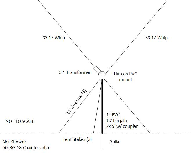
Antenna #10, Elevated V-Dipole (80-6m, 10’ raised mount)
- CHA MPAS Hybrid Mini with right-angle PL-259 to SO-239 adapter
- CHA SS-17 (2)
- CHA Hub
- Landscape spike
- Two 5’ PVC pipe with coupler and 3/8-24 top mount
- PVC mount guys, 13’ 1/8” orange paracord, 3 each with carabiners and adjusters, stakes
- Hybrid 3/8-24 accessories, tools, Ox-Gard
- CHA 50’ RG-58A Coax (PL-259 to PL-259) with SO-239 to BNC-Male adapter
- Small rubber mallet
Set landscape spike with mallet, add hub to PVC 3/8-24 top mount, add hybrid to hub angle side, attach coax to hybrid with choke at antenna end, attach SS-17 to hybrid top and SS-17 to Hub opposite angle side, extend both SS-17 to full length, assemble PVC pipe and top PVC mount, raise assembly with PVC pipe into position over base spike, extend guy ropes and stake mast vertical, fasten coax to mast or wrap coax one to two turns around mast, roll out coax and attach to radio. Safety/hazard check system deployment.

Antenna #11, Elevated Horizontal Dipole (80-6m, 10’ raised mount)
- CHA MPAS Hybrid Mini with right-angle PL-259 to SO-239 adapter
- CHA SS-17 whips (2)
- CHA Hub
- Landscape spike
- Two 5’ PVC pipe with coupler and 3/8-24 top mount
- PVC mount guys, 13’ 1/8” orange paracord, 3 each with carabiners and adjusters, stakes
- CHA 50’ RG-58A Coax (PL-259 to PL-259) with SO-239 to BNC-Male adapter
- Small rubber mallet
Set landscape spike with mallet, add hub to PVC 3/8-24 top mount, add hybrid to hub side, attach coax to hybrid with choke at antenna end, attach SS-17 to hybrid top and SS-17 to Hub opposite side, extend both SS-17 to full length, assemble PVC pipe and top PVC mount, raise assembly with PVC pipe into position over base spike, extend guy ropes and stake mast vertical, fasten coax to mast or wrap coax one to two turns around mast, roll out coax and attach to radio. Safety/hazard check system deployment.

Antenna #12, NVIS Inverted 25' Wire Dipole on 10’ mast (80-6m)
- CHA MPAS Hybrid Mini with right-angle PL-259 to SO-239 adapter
- Two 25’ red counterpoise/elements w/ 3/8” lugs, stakes
- Landscape spike
- Two 5’ PVC pipe with coupler and 3/8-24 top mount
- PVC mount guys, 13’ 1/8” orange paracord, 3 each with carabiners and adjusters, stakes
- Hybrid 3/8-24 accessories, tools, Ox-Gard
- CHA 50’ RG-58A Coax (PL-259 to PL-259) with SO-239 to BNC-Male adapter
- Small rubber mallet
Set landscape spike with mallet, add hybrid to PVC 3/8-24 top mount connecting one 25’ antenna wire at bottom of hybrid connection (at mount), attach coax to hybrid with choke at antenna end, attach 25’ antenna wire to hybrid top, assemble PVC pipe and top PVC mount, raise assembly with PVC pipe into position over base spike, extend guy ropes and stake mast vertical, extend and stake two 25’ antenna wires in opposite directions, fasten coax to mast or wrap coax one to two turns around mast, roll out coax and attach to radio. Safety/hazard check system deployment.
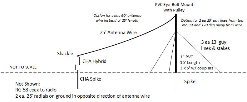
Antenna #13, Short Sloping Wire Configuration (80-6m, 25’ wire from ground mounted hybrid to elevated far end 10-15’ mast)
- CHA MPAS Hybrid Mini with right-angle PL-259 to SO-239 adapter
- CHA TDL 25’ antenna/counterpoise wire on winder
- CHA Ground spike
- Two 25’ red counterpoise/elements w/ 3/8” lugs, stakes
- Landscape spike
- Two 5’ PVC pipe with coupler and pulley eye-hook top mount
- PVC mount guys, 13’ 1/8” orange paracord, 3 each with carabiners and adjusters, stakes
- Hybrid 3/8-24 accessories, tools, Ox-Gard
- CHA 50’ RG-58A Coax (PL-259 to PL-259) with SO-239 to BNC-Male adapter
- 25’ paracord, line tensioner, stake with eye-hole loop
- Small rubber mallet
Set ground spike with mallet, add hybrid with 2 ea 25’ counterpoise wires at GND end, attach coax to hybrid with choke at antenna end, attach 25’ antenna wire with shackle strain relief to hybrid top, extend antenna wire in direction of elevated end, set landscape spike at end of extended antenna wire, attach paracord to 25’ antenna wire end, pass through pulley, attach rope mast guys to eye-hook top mount, add masts and coupler to top mount, raise mast into position and stake vertical, tension antenna wire and fix guy end at stake, extend and stake counterpoise wires opposite direction of antenna wire (120 deg), roll out coax and attach to radio. Safety/hazard check system deployment.
Antenna #14, Tall Vertical (whip on 10’ PVC mast mount), lugged shield to hybrid on ground, ground radials (80-6m)
- CHA MPAS Hybrid Mini with right-angle PL-259 to SO-239 adapter
- CHA SS-17 whip (1)
- CHA Ground spike
- Landscape spike
- 12’ insulated braid wire with 3/8” lugs at each end
- Four 25’ red counterpoise/elements w/ 3/8” lugs, stakes
- Two 5’ PVC pipe with coupler and 3/8-24 top mount
- PVC mount guys, 13’ 1/8” orange paracord, 3 each with carabiners and adjusters, stakes
- Hybrid 3/8-24 accessories, tools, Ox-Gard
- CHA 50’ RG-58A Coax (PL-259 to PL-259) with SO-239 to BNC-Male adapter
- Small rubber mallet
Set CHA ground spike with mallet, add hybrid with four red counterpoise wires at hybrid bottom and feed end of lugged shield connection to top of hybrid using 3/8-24 accessories, attach coax to hybrid with choke at antenna end, set landscape spike with mallet ~12” away, pre-assemble PVC mount guys onto 3/8-24 top mount guy points, assemble PVC pipe and top PVC mount, attach SS-17 and antenna end of lugged shield connection onto 3/8-24 PVC top mount, extend SS-17, raise assembly with PVC pipe into position over base spike, extend guy ropes and stake mast vertical, extend and stake counterpoise/radials, roll out coax and attach to radio. Safety/hazard check system deployment.
Antenna #15, Raised Portable Vertical, SS-17 on Hub/PVC mast with single directional radial SS-17 whip (80-6m)
- CHA MPAS Hybrid Mini with right-angle PL-259 to SO-239 adapter
- CHA SS-17 whip (2)
- CHA Hub
- Landscape spike
- Two 5’ PVC pipe with coupler and 3/8-24 top mount
- PVC mount guys, 13’ 1/8” orange paracord, 3 each with carabiners and adjusters, stakes
- CHA 50’ RG-58A Coax (PL-259 to PL-259) with SO-239 to BNC-Male adapter
- Small rubber mallet
Set landscape spike with mallet, add hub to PVC 3/8-24 top mount, add hybrid to hub top, attach coax to hybrid with choke at antenna end, attach SS-17 to hybrid top and second SS-17 to Hub side, extend both SS-17 to full length, assemble PVC pipe and top PVC mount, raise assembly with PVC pipe into position over base spike, point single horizontal SS-17 in direction of desired contacts, extend guy ropes and stake mast vertical, fasten coax to mast or wrap coax one to two turns around mast, roll out coax and attach to radio. Safety/hazard check system deployment.
(Antenna is similar to Antenna 11, with the hybrid and one whip mounted on the hub pointed up.)
Antenna #16, Off Center Fed Dipole (on 15’ mast) using 25’ and 60’ antenna wires (160-6m)
- CHA MPAS Hybrid Mini with right-angle PL-259 to SO-239 adapter
- Landscape spike
- One 25’ red counterpoise/elements w/ 3/8” lugs, stake
- CHA 60’ antenna wire on winder, stake
- Three 5’ PVC pipe with coupler, eye-hook mid-length coupler, and 3/8-24 top mount
- PVC mount guys (13’ 1/8” orange paracord, 3 each with carabiners and adjusters, stakes, bag)
- Two 25’ yellow paracord guys with tensioners, stakes
- Hybrid 3/8-24 accessories, tools, Ox-Gard
- CHA 50’ RG-58A Coax (PL-259 to PL-259) with SO-239 to BNC-Male adapter
- Small rubber mallet
Set landscape spike with mallet, add hybrid to PVC 3/8-24 top mount connecting 25’ antenna wire at bottom of hybrid connection (at mount), attach coax to hybrid with choke at antenna end, attach 60’ antenna wire to hybrid top with strain relief shackle, attach two 25’ guys to 3/8-24 top mount guy points, assemble PVC pipe, couplers, and top PVC mount, raise assembly with PVC pipe into position over base spike, extend 10’ coupler guy ropes and stake mast vertical, extend and stake two antenna wires in opposite directions, extend and stake 25’ top guys orthogonal to dipole, fasten coax to mast or wrap coax one to two turns around mast, roll out coax and attach to radio. Safety/hazard check system deployment.
(Antenna is similar to Antenna 12, with the top connected 25' wire replaced with a 60' wire.)
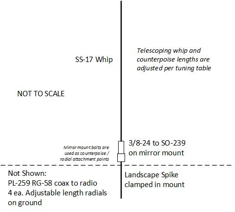
Antenna #17, Basic Vertical (BV), 20-6m
- 3/8-24 ground mount/spike with PL-259 to SO-239 adapter
- CHA SS-17 whip (1)
- Four 9’ yellow counterpoise (marked for shorter lengths) with 3/8” lugs, stakes
- CHA 12’’ RG-58A Coax (PL-259 to PL-259) with SO-239 to BNC-Male adapter
- Small rubber mallet
Set mount with mallet, attach coax with choke at antenna end, attach and extend four counterpoise per BV setup table, stake counterpoise wires, attach SS-17 to mount and extend to length per BV setup table, roll out coax and attach to radio with extension lengths as needed. Safety/hazard check system deployment.
| Whip Length | |||||
| Band | Frequency | Feet | Inches | Sections Up | Radials |
| 20 | 14.18 | 17 | 0 | Fully Extended | 4 x 12' 6" |
| 17 | 18.12 | 12 | 7 | Seven and a half | 4 x 12' 6" |
| 15 | 21.23 | 11 | 5 | Six and three-quarters | 4 x 9' |
| 12 | 24.945 | 9 | 7 | Five and a half | 4 x 6' |
| 10 | 28.51 | 8 | 10 | Five and a quarter | 4 x 5' |
| 6 | 52.025 | 4 | 0 | One and a quarter | 4 x 3' |
Will add additional configurations as time permits...
NOTE: No claim is made to any Chameleon Antenna owned copyrights, trademarks, or other company produced information.