My HF Receiver Collection
24 May 2019
Introduction
1920s - 1950s
1960s
1970s
1980s
1990 - today
Introduction - 1920s to 1950s
This is the era of 'steam radio', as all the receivers are valve operated. In my collection, a few of the later ones, from the 1950s, are still operational, notably the Eddystone 680X and the Collins 51J-4 and 75S-1. Tremendous changes evolved over this period,
from TRF to superhet radios, through wartime developments, to very high performance communications receivers.
RCA Radiola III-A (1924)
This is a very early four valve regenerative AM receiver, covering 220 - 550m (540 kHz to 1.4 MHz). It's not operational,
as I don't have the appropriate valves (UX199 and UX120 or later WD11). The first stage is a regenerative detector, followed by an audio
amplifier, and a push-pull audio output pair capable of driving a loudspeaker.
Inside, the condition is remarkable, although the rubber shock-absorbers for the valve sockets
have collapsed. It was designed to run off one A cell for filaments, and a collection of 22.5 and 45V batteries for HT. The headphone/
speaker connections are live to the HT!
The receiver is mounted in a sturdy french polished wooden box with dovetailed corners, about 300 x 170 x 120 mm. The front panel is
made of pressed Bakelite. I was given the receiver while working in the USA in the late 1990s.
Original tube lineup: UX199, UX199, UX120, UX120.
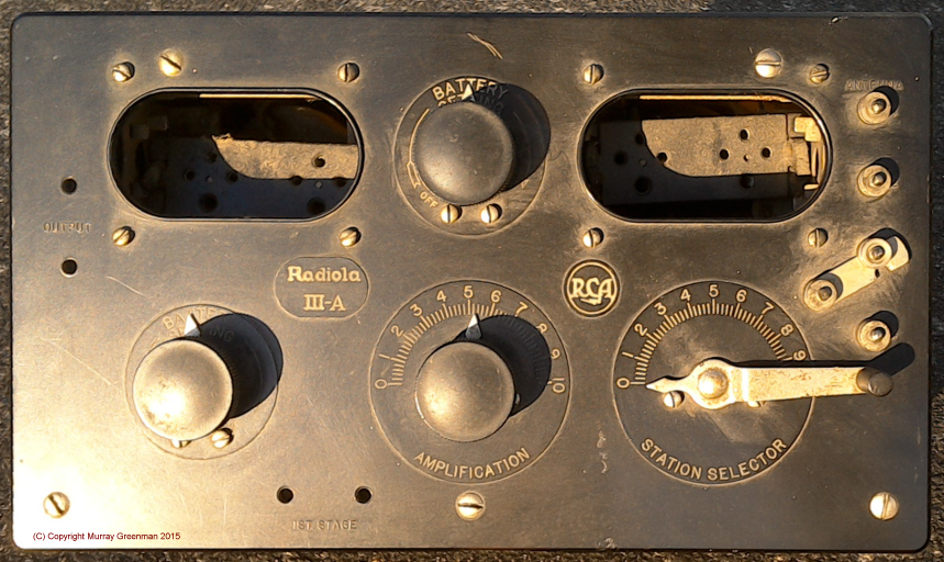
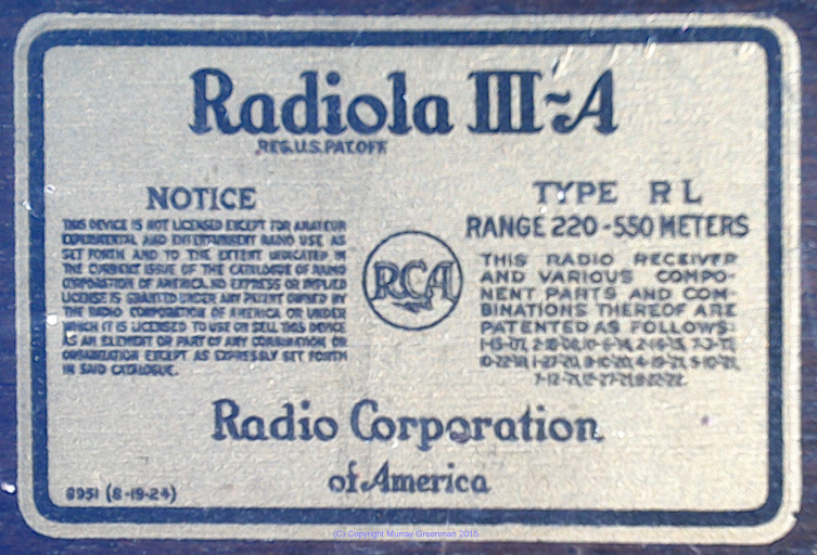
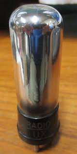
The Radiola III-A (left),
the original rear-panel label (centre, 1.5 x life size), and a UX199 valve (right)
Make sure you check out all the detailed photos in the list above. I recently found some reasonable replicas of the original 'tubes' (valves)
as you will see here. The 'tubes' are actually 'Edison style' LED garden lights
with silvered glass envelopes, and glow yellow when powered up. They look remarkably realistic!
RCA Radiola III (1924)
This is the smaller brother of the Radiola IIIA. The first two stages are virtually the same, a regenerative detector, followed by a transformer coupled headphone amplifier.
The interior looks like new, and the exterior is also in very good condition, despite surviving for 93 years.
The receiver is mounted in a sturdy french polished wooden box, about 200 x 165 x 120 mm. The front panel is
made of pressed Bakelite. I was given the receiver in 2017 by a friend, Doug Lux WB6VAC. It came with the original manual and CAMCO 'Cannon-ball Junior' headphones.
At some point in the last 50 years, the tubes have been replaced with 'pencil tubes', a CK505AX and a CK512AX. I have yet to find out if it works. The radio operates from 22.5 V (detector) 45 V (audio stage), 1.5 V filaments and a separate 1.5 V bias battery. The power lead looks new, and is braided with individual metal identification tags on each lead. The leads end in automotive bullet connectors.
Original tube lineup: UX199, UX199.
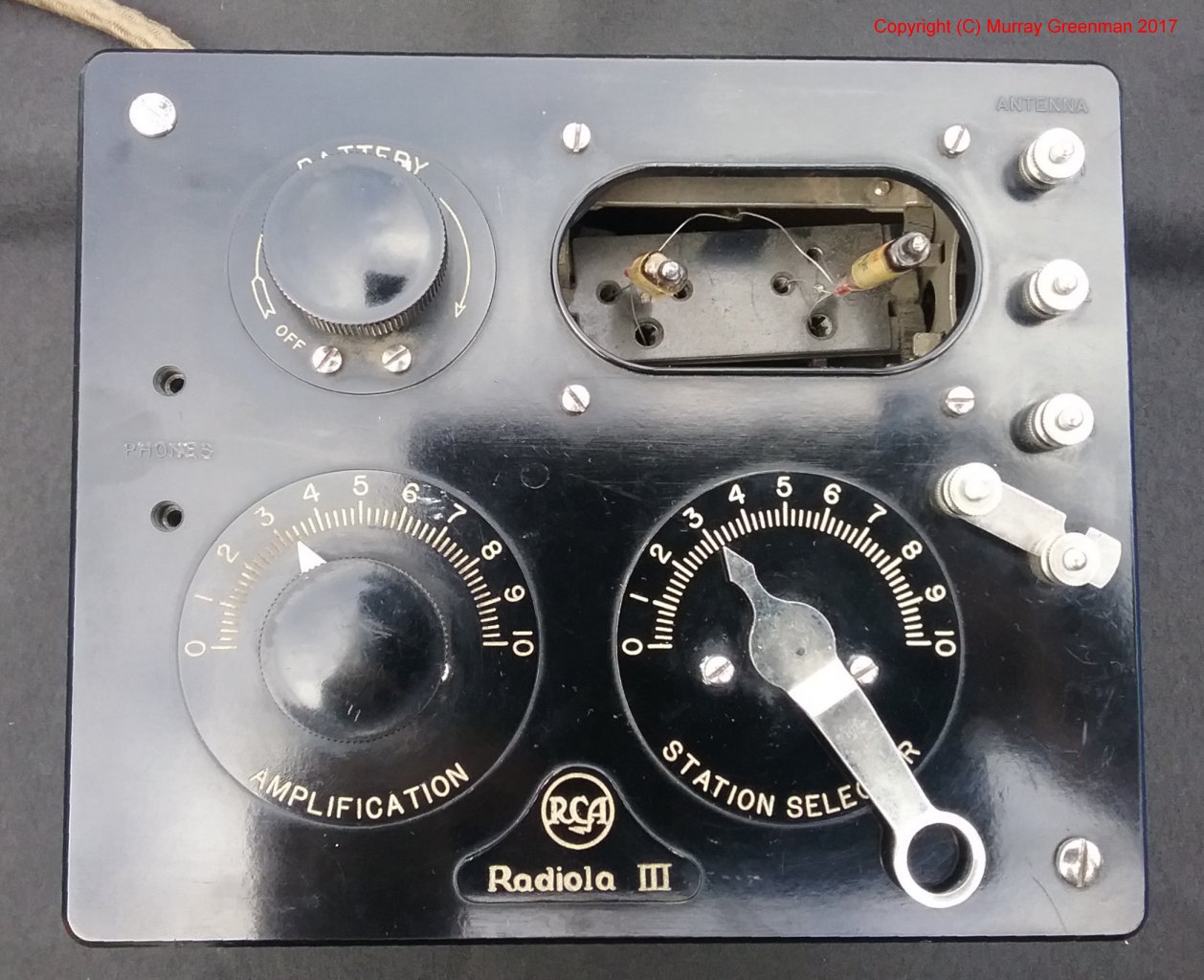
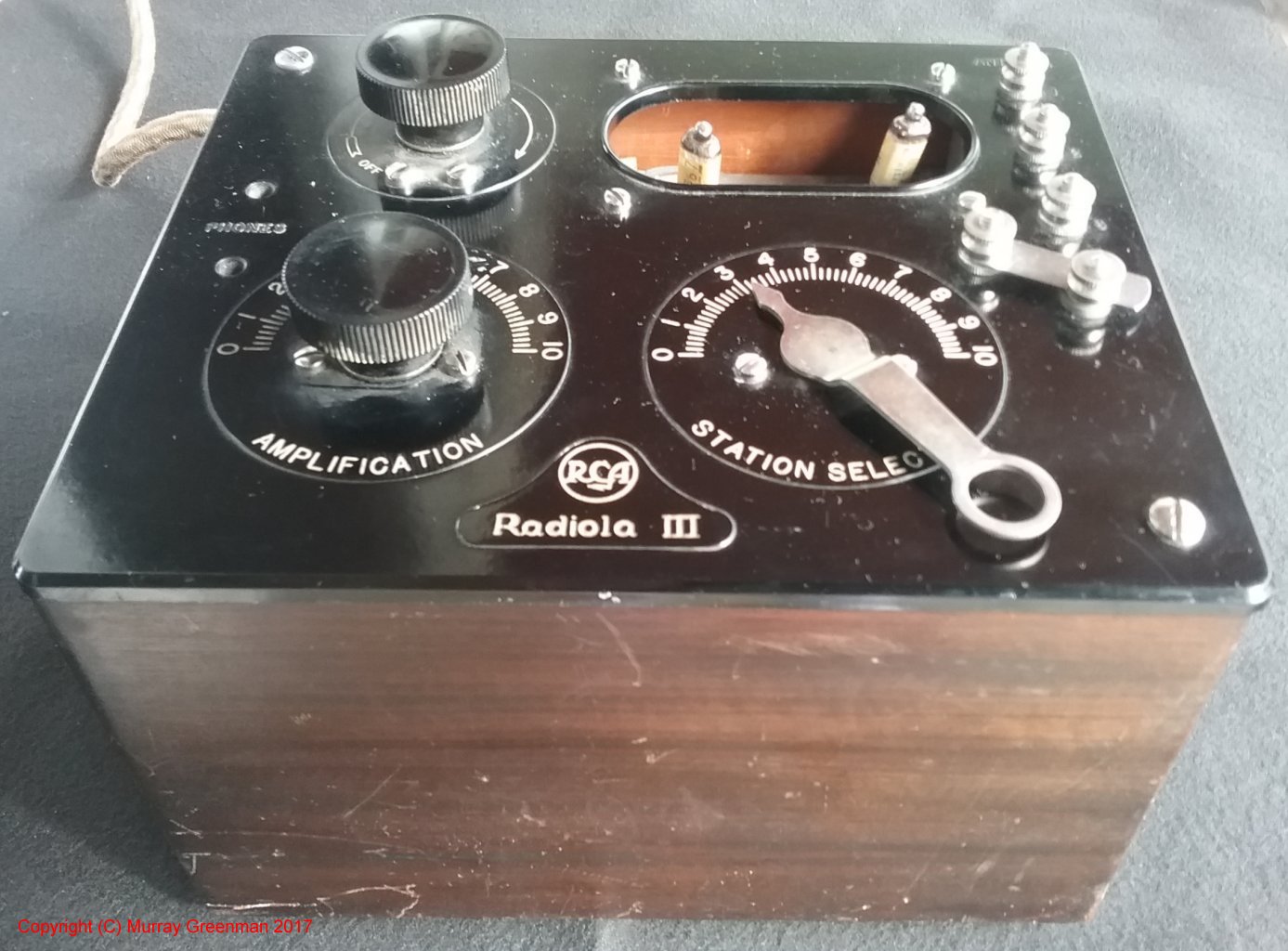
The Radiola III top view and
oblique view
Looking at the picture on the left, the 'Amplification' control adjusts the reaction of the detector stage, using
a variometer within the detector coil. The 'Station Selector' tunes in the stations, using another variometer
within the antenna coil. The knob top left adjusts the filament current (large rheostat), and acts as the On-Off switch.
The terminals top right are the antenna connections (top) and the band 'switch' with link below. There are three
operating ranges, 535 - 950 kHz, 625 - 1200 kHz and 830 - 1500 kHz.
In the interior views (links below), you can see the large coils and variometers, and the other details described above.
In 1924, this radio cost $24.50, or about six week's wages, yet despite this, the radio was hugely popular.
For $24.50 today (pocket change), you could buy two AM/FM/Short Wave synthesised radios like
this one!
Wavemeter Collection (1941 - 1963)
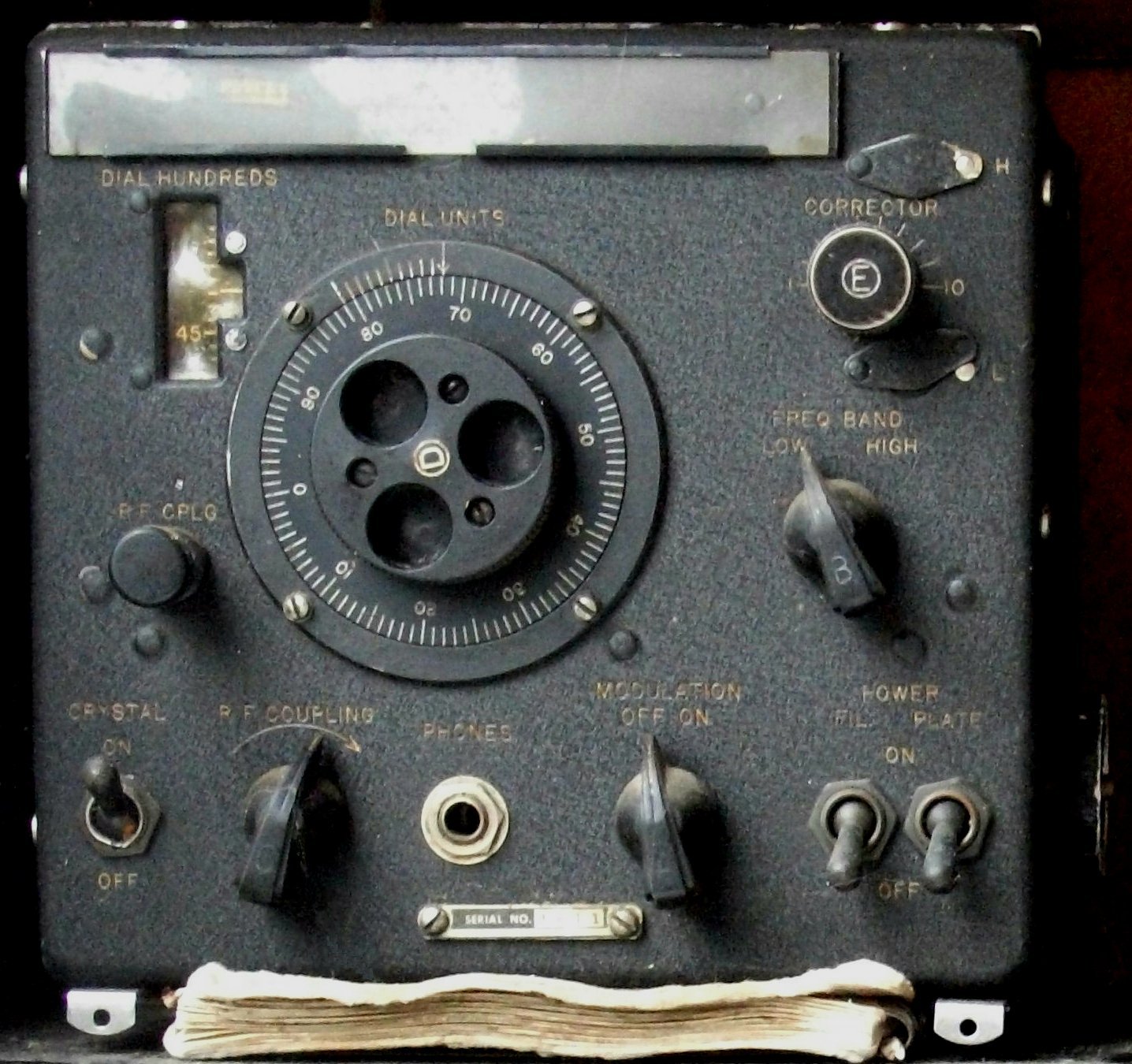
I've lumped these four units together here for convenience (and although interesting, they aren't really receivers). In the picture below, the one at the top left is
a US Navy LM-10 crystal calibrator/wavemeter, dating from about 1943, manufactured by Bendix Radio. It is in reasonably original condition, and still operational. It still
has the original calibration booklet (underneath it). As well as operating as a heterodyne wave meter (there was a 1 MHz reference crystal and a calibrated VFO), the
LM-10 could AM modulate its oscillator at 400 Hz for use with AM receivers. The calibration books were individually calibrated and printed.
On the bottom left is a similar vintage (1942) BC-221-AF, built by Bendix Radio for the US Army. It has lost the
original case and is not operational, but I do have the original calibration booklet and the schematic plate from the case. These units were battery operated
and of very similar construction to the LM-10, although they lacked the modulated oscillator capability of the LM-10.
The RCA TE-149 wavemeter (bottom right) was made in Canada by the RCA Victor Company in 1941, and operated in a similar way to the LM-10 and BC-221.
Although the case is complete, the internal circuit
ry has been 'got at' in an attempt to use solid state devices, and it isn't working. I now have a second one, complete with tubes,
but lacking the case. The TE-149 has an unusual tuning mechanism with a spiral disc which operates the tuning pointer,
which points to a spiral scale on the visible side of the disc.The unit was also battery operated, but was not capable of the
frequency accuracy of the LM-10 or BC-221, as it lacked interpolation capability and therefore had no calibration book.
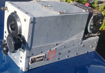
The final unit (blue box top right) is a simple passive wavemeter dating from 1963, and built for the Navy. It covers 0.1 to 35 MHz. The unit has no detector or indicating device -
it's just a tuned circuit. It's title (believe it or not) is '6625-99-972-6347 Detector Radio Frequency'.
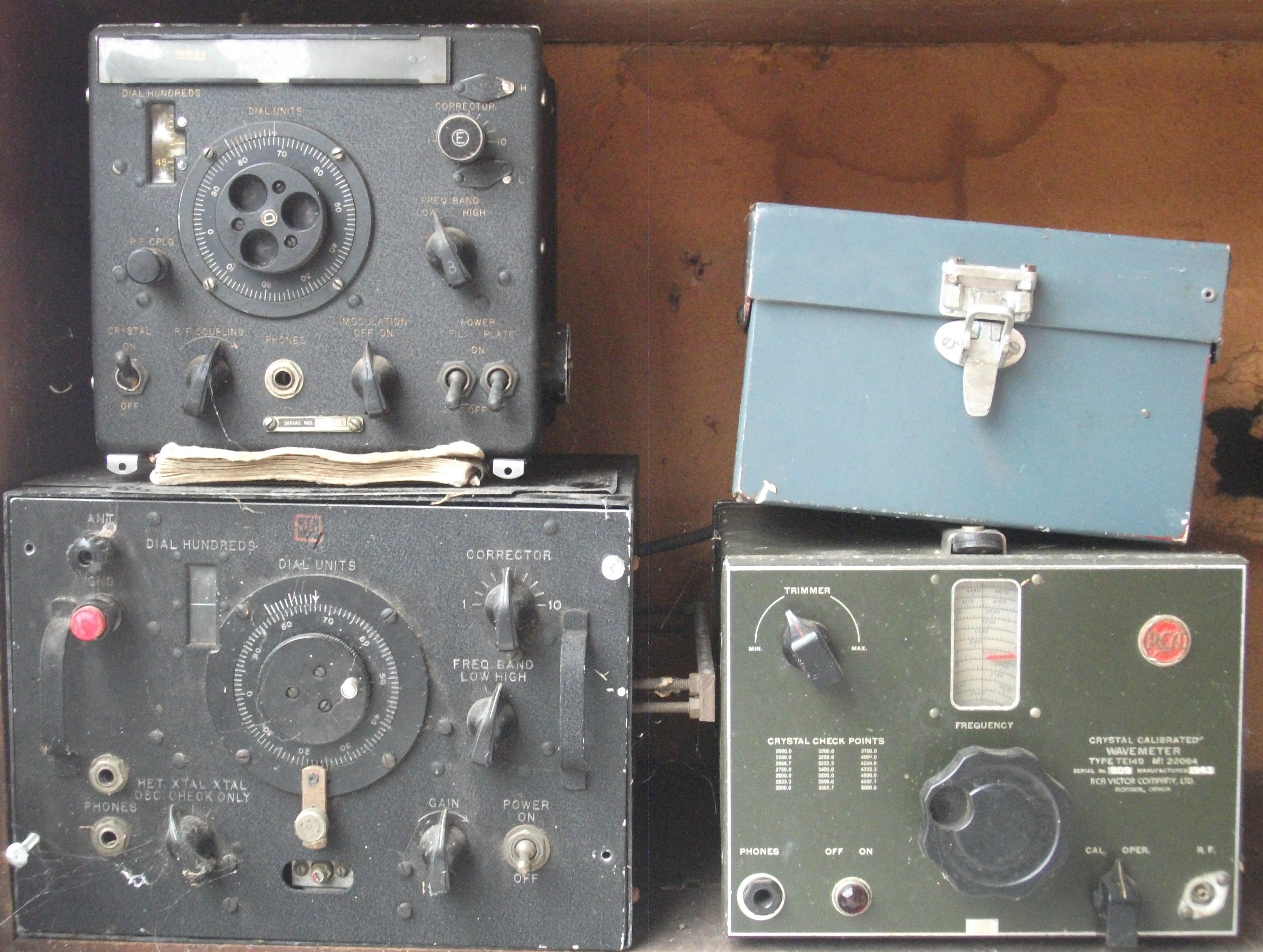
The four wavemeters (left)
The Bendix LM-10 (right)
Belmont Mantel Radio (1940)
By the 1940s, superheterodyne design was common, making radios more stable and much easier to tune.This radio was (I understand from family lore) built from a kit by my
father during the Second World War. However the case and chassis are clearly commercial, and the brand name on the dial plate 'Belmont' belongs to a Chicago firm. The radio is
230V operated, and clearly has some local components (such as the Rola EM speaker). It's my guess that the radio was actually assembled in New Zealand, and (possibly)
was available at the time as a semi-kit. The valves are Octal types. It is a conventional four-valve plus rectifier design with a wooden case embellished with marquetry veneer.
The veneer continues in a smooth radius around the sides, and it's my guess that the veneer was laid up and moulded in a jig.
Tube lineup: 6A8, 6K7, 6U7, 6F6, 80.
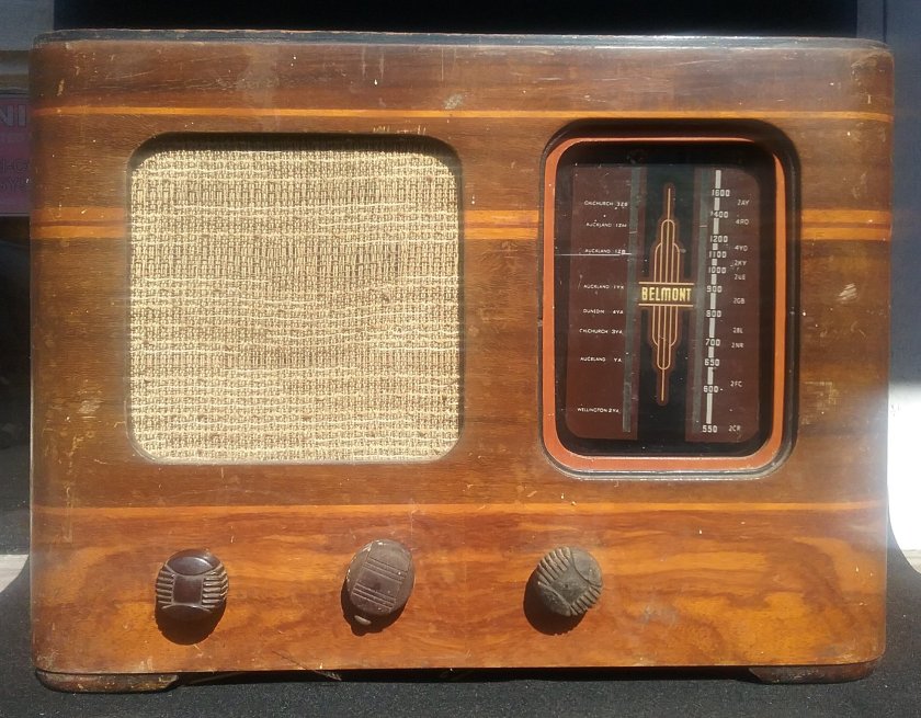
Belmont mantel radio (left), and a
rear view (right)
AN/ARC-5 (SCR-274N) and BC-45xx (~1944)
These deservedly famous receivers were built for the US Navy and US Army by Western Electric and other contractors. There were numerous look-alike but not necessarily
compatable models, covering 190 kHz to 156 MHz. All are single-band receivers. The two that I have are the US Army BC-453-B (3 - 6 MHz),
and the US Navy R23/ARC-5 (190 - 550 kHz).
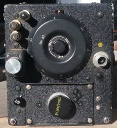
R23/ARC-5 190-550 kHz (left),
BC-453-B 3-6 MHz (right)
The receivers are single conversion of conservative design, robust and stable. The different models use different IF
frequencies: for example 85 kHz for the LF receiver and 1415 kHz for the 3-6 MHz models. The receivers are 28 Volt operated,
and include a small motor-generator (visible in the picture on the right above). The tube lineup is VT-131 (12SK7), VT-132 (12K8), 2x VT-131, VT-133 (12SR7) and VT-134 (12A6).
Essentially an AM receiver with optional BFO, the receiver worked well on CW and would demodulate SSB quite well when the
RF gain was used to manage the signal. The two IF stages have AGC, and there is delayed AGC on the RF amplifier. There is no
audio gain control. Intended for remote control, the tuning was operated by a Bowden cable plugged into the panel to the right
of the dial, although amateur users quickly adapted the receivers to a local knob (right picture above). The gain control, power and
BFO switches were also remote (see sub panel on left receiver above). Again these controls were usually adapted by amateur users
with a small home-made sub-panel (on right receiver above).
Marconi R1475 (1948)
Created at a time when post-war austerity forced considerable limitations on design and manufacture, the R1475 (sometimes known
as the 88 set, since that's what's on the label) was designed as a ground station receiver, primarily for the RAF. There are interesting
similarities to the wartime 1155 and postwar AD94 models from the same company.
The system consists of the Type 88 receiver, and the Type 360 power supply (which I don't have). The CW/AM receiver operates from 2 to
20 MHz in four bands. The receiver is tropicalised, is vibration resistant, and designed for harsh conditions, -40 to +40 �C. The receiver is single conversion with an IF of about 600 kHz. The BFO (crystal controlled on 600 kHz) is used as a marker, and corresponding calibration points are indicated on the dial every 600 kHz.
There is an RF preselector which provides good sensitivity and image rejection. Oddly, two bands are served by each set of coils.
The unusual tuning dial arrangement was designed to provide � 2 kHz setting accuracy or better throughout the tuning range. The four bands have individual edge-viewed dial scales
mounted on a 75 mm diameter drum. The drum is rear-lit, each band illuminated separately when selected.
The higher two bands tune faster than the lower two, and the multi-turn nature of the dial (with individual pointers which follow
the tuning) provides very wide band spread, six full turns of the drum on the lower bands, 12 on the upper bands (effective scale
length on these bands almost 3 metres). The wiggly line across the dial drum cover is an individually calibrated cursor, used to compensate for slight non-linearity in the tuning mechanism.
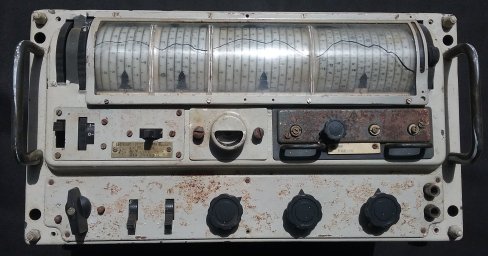
The Marconi R1475 front view (left),
and rear view (right).
As you can see, my R1475 has a fairly rusty front panel. It has clearly been repainted at some point (originally RAF grey or black),
but it is essentially undamaged, and is very clean inside. The internal shields and other metalwork, and even the case,
are silver plated.
The various stages are all mounted in individual plug-in modules along the back of the receiver, while the band switch
and the mode switch traverse through the modules from the side.
The R1475 includes a 'magic eye' tuning indicator (near the centre in the front view), and a plug-in Guard Receiver (to the right).
The guard receiver is crystal controlled and monitors a special calling frequency. The output feeds directly into the main
IF chain, and has its own RF gain control. The knob on the module is a frequency trim.
The controls along the bottom are (left to right) Mode, Limiter, AVC, AF Gain, Scale Trimmer, Guard RF Gain and two headphone
sockets. Along the middle row are
a Scale Lock, RF Gain, Guard Selector Switch, Tuning Indicator and the Guard Receiver. To the left of the display drum
(at the top) are the edge-operated Fast and Slow Tuning Wheels, and on the right of the drum, the Band Switch.
The local oscillator has bimetal-operated thermal temperature compensation. Selectivity is provided by double-tuned IF coils
with two selectivity settings, and an additional audio filter for CW. Front panel audio output is intended only for headphones.
There are line and high level outputs on the back.
There are 13 Octal-family tubes, including a voltage regulator and tuning indicator. Power requirement is about 60 Watts,
250 V DC 65 mA, and 12V AC or DC, 1.8A. The matching Type 360 power supply will operate off AC mains or 12V DC, using a vibrator. I've not attemped to restore the receiver yet - but I will. I did sling together a power supply to test it, and it works! Not very well, but
I can hear signals. This is therefore currently my oldest working radio.
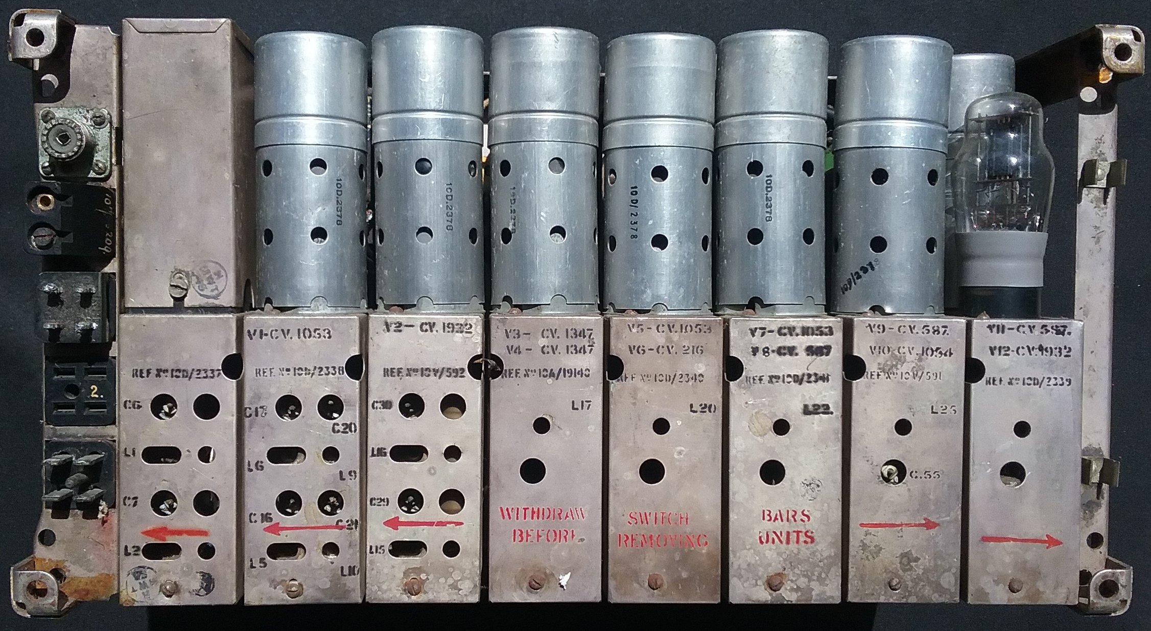
Ultimate (Radio 1936 Ltd) Mantel Radio (1950)
This radio represents the typical 'mantel radio' of the 1940 - 1960 period. It uses the (then) new Loctal type valves,
which were more compact than the earlier types, and had a secure lock-in base which made them useful in car radios subject to vibration. The Ultimate brand was manufactured
in New Zealand for many years by Radio (1936) Limited, until they were eventually absorbed by Pye. Radio 1936 Ltd manufactured many of their own parts.
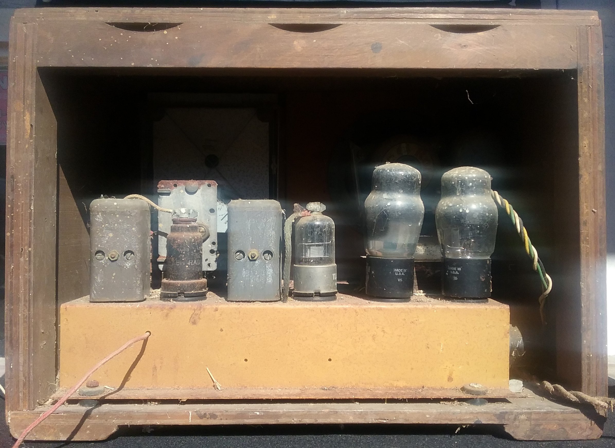
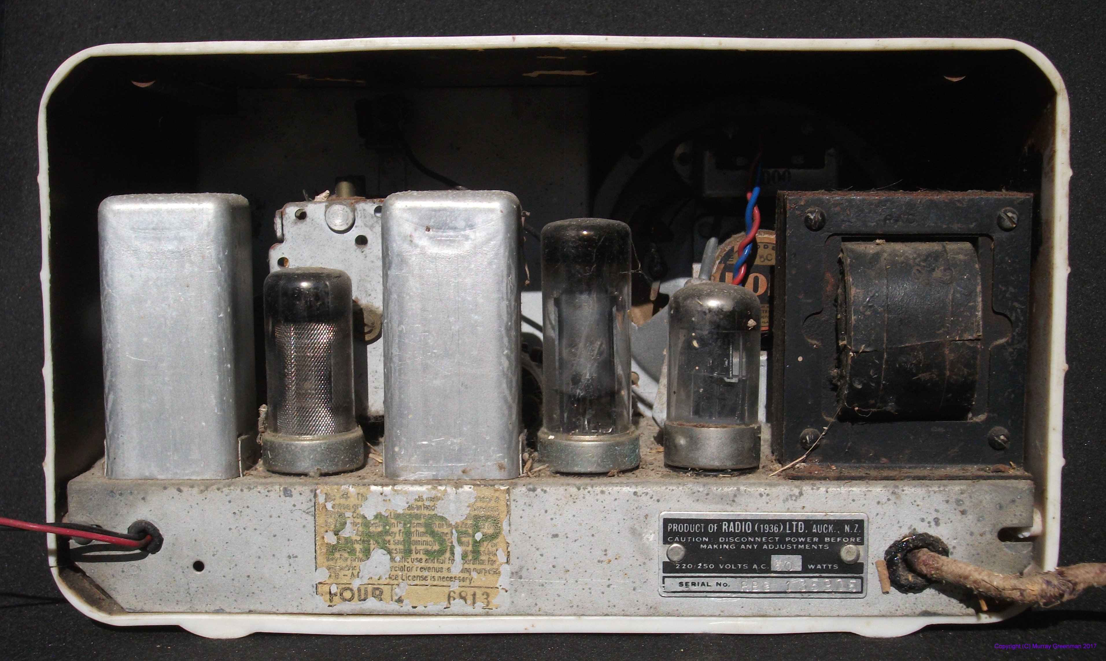
This radio represents economy of design: the valves are a mixer/oscillator, an IF amplifier and a single high gain audio output tube which incorporates
the detector diode, plus a rectifier tube. The last mentioned three valves can be seen left to right in the rear view picture. The mixer/oscillator is hidden
behind the left-most can. The two cans are of course the two IF double-tuned circuits. The case is moulded from casein, an early plastic material.
The loudspeaker was made in Australia by Rola. On the rear panel, in addition to the model and serial number label, you can see the remnants of
the 'ARTS&P' transfer, which states that the radio was manufactured subject to a range of licences for private use. 'ARTS&P' stood for
'Australian Radio Technical Services & Patents Co. Limited', who were patent attorneys and representatives at the time. Many of the
developments in radio receiver design were then still subject to patent restrictions. (The patents for radio valves and the superheterodyne
technique eventually expired in the mid 1960s).
Tube lineup: Loctal series, ECH21, EF22, EBL21, EZ21.
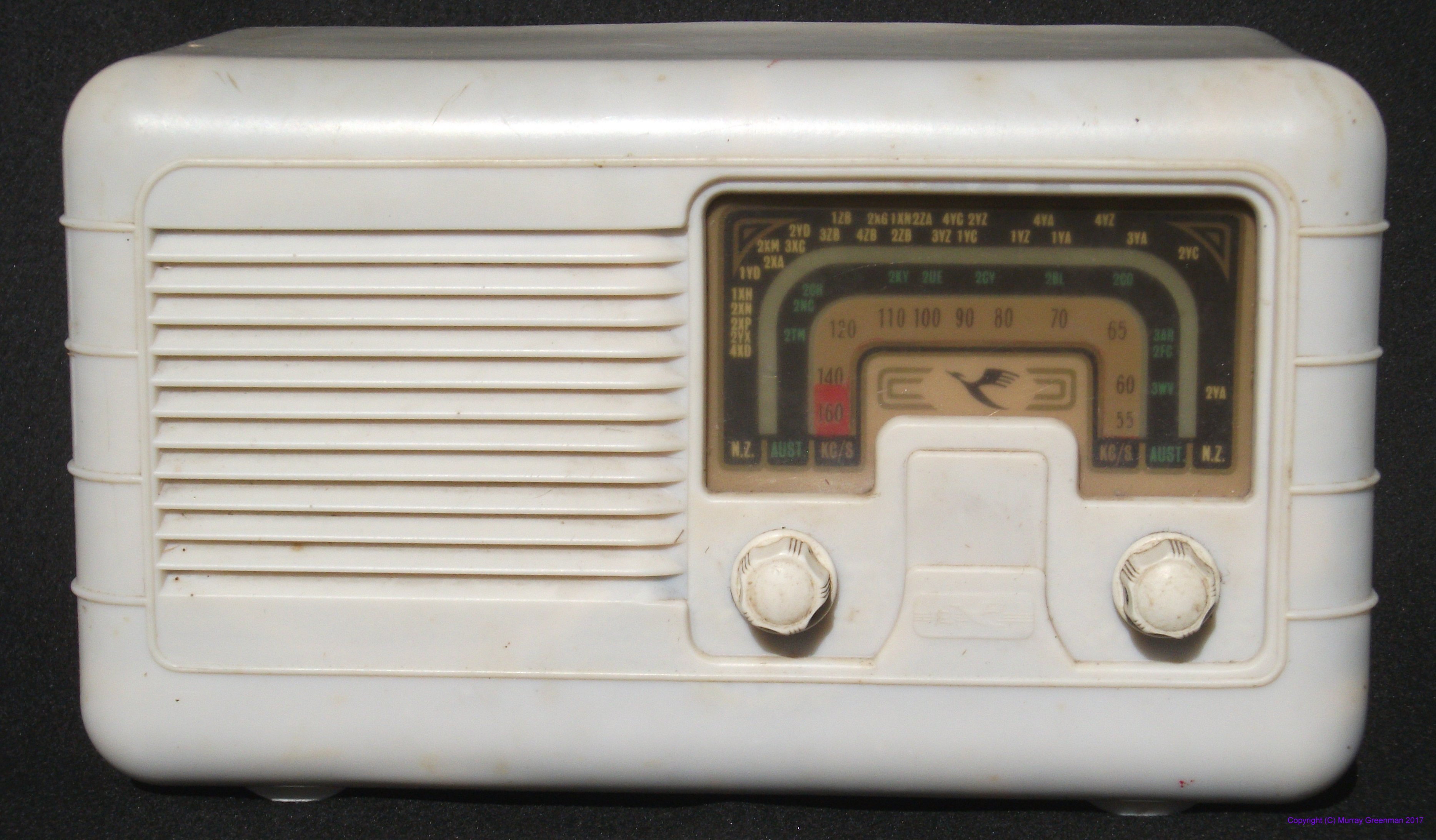
Ultimate mantel radio (left), and a
rear view (right)
My grandmother bought this radio new, and it was left to me when she died in 1953. It was my first radio receiver, and I used it to listen to 'DX' broadcast
stations from Australia and beyond.
Eddystone 680X (1951)
The next receiver is a true general coverage HF receiver. It covers 480 kHz to 30 MHz in five bands,
and sports the now famous Eddystone 'slide rule' dial. The receiver has 15 valves, mostly miniature, including a voltage regulator for the oscillators.
It is interesting to compare this Eddystone with the next one, as although they have similar appearance, this one is much more complex.
It has two RF stages, two IF stages, and push-pull audio output.
The receiver is too early to have a product detector, so SSB reception is poor, although CW is adequate. The receiver has adjustable IF
bandwidth, with four settings, as well as a single-crystal filter in a phasing network. The power supply tends to generate noise, so it
needs to be used with a remote antenna and shielded antenna lead.
The receiver covers the MF and HF range in five bands: 480 - 1110 kHz, 1.1 to 2.5 MHz, 2.5 to 5.7 MHz, 5.3 to 12.5 MHz and 12.3 to 30 MHz. It would at the time have been an expensive receiver - the original cost when new was UKP 106 (about US$200).
It uses largely B7G minuature valves. The exceptions are the rectifier and voltage regulator tubes. Plenty of audio is provided
by the push-pull audio output stage.
The 680X is single-conversion, with an IF of 450 kHz, and two RF stages to give improved RF selectivity to avoid image responses.
Performance is adequate, although it is a bit flat above 15 MHz. Not small, the receiver is 450 mm wide and 220mm high, 300mm deep,
and weighs over 21 kg.
The front panel is diecast, and the case is finished in hammerglaze grey. It took me a while to find the headphone socket - it's on the left side!
Tube lineup: 6BA6 x2, 6BE6, 6AM6, 6BA6 x2, 6AL5, 6BR7 x2, EL91 x2, 6BA6, 6AL5, 5Z4G, VR150
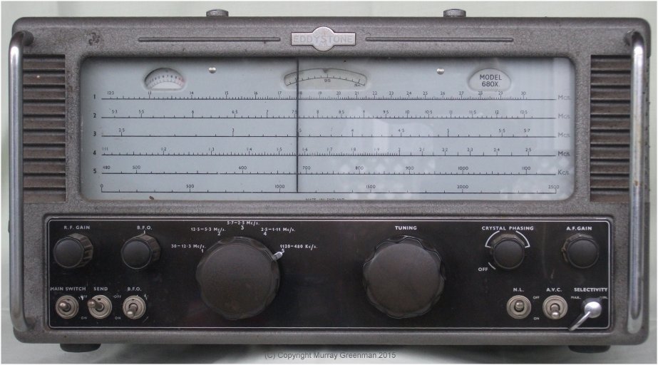
The Eddystone 680X
Eddystone 840A (1954)
The external appearance of the 840A is quite similar to the 680X, but inside it is a very different beast. Built for a different market
(as a 'cabin radio' for use on ships, and as a domestic radio in 'The Colonies'), and in a different price range, the 840A has
only one RF stage, and only one IF stage. The most important difference is that it is an AC/DC set, so will operate
from 110V, 200 or 230V, AC or DC. DC
supply used to be common on ships and for home lighting plants in remote places. There are only seven valves, and no 'S' meter on the panel.
The valves are from the 'Noval' 100mA filament U series.
My example has been 'got at' to some extent. The ballast resistor is missing, so it is committed to run from 110V AC; there are various
internal 'improvements', plus an 'S' meter had been fitted through a hole in the top of the cover. The BFO knob to the right of the
Tuning knob is not the original one.
The panel layout is different to the earlier receiver, and having no crystal filter, the corresponding knob is replaced with a Tone
control. While the main tuning dial is the usual large slide-rule affair, there are only four bands: 480 - 1400 kHz, 1.4 to 3.8 MHz,
3.7 to 10.6 MHz, and 10.5 to 30 MHz. In this receiver, Amateur and Broadcast bands are marked on the dial in blue and red respectively.
The brochure comments that the receiver covers the 500 kHz marine frequency.
The receiver has the same width and height as the 680X (450 mm x 220 mm) but is only 230 mm deep. It's considerably lighter than the 680X.
I can't comment on the performance yet, as this radio has yet to be restored.
Tube lineup: UAF42 x4, UCH42, UL41, UY41.
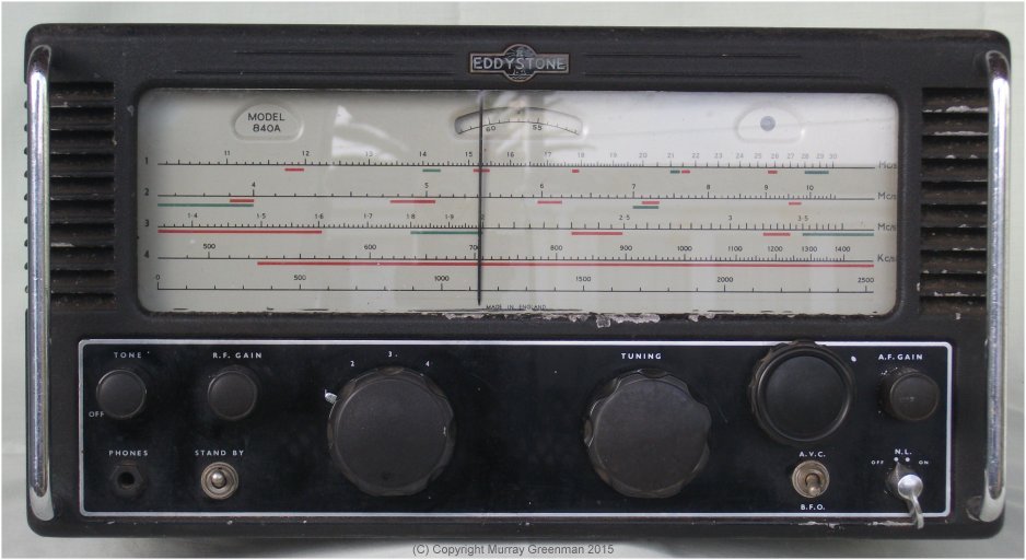
The Eddystone 840A (unrestored)
Collins 51J-4 (1955)
This is arguably the best of my valve receivers. Even today the performance is impressive. It is very stable, as it uses the famous Collins
PTO (permeability tuned oscillator). The receiver covers 540 kHz to 30.5 MHz in 30 x 1 MHz bands. Band change is achieved using switched
slug-tuned coils. The coils are ganged and track with the tuning knob, and the dial scales are on a drum which rotates with the band change knob.
There are 16 miniature valves.
The first IF is tunable in two ranges (0.5 to 3.5 MHz), and is followed by a second IF at 500 kHz, which has both a phasing crystal filter
and a useful range of mechanical filters. The receiver is superbly stable, has good sensitivity, excellent calibration, and is a great AM/CW
receiver. With no product detector, SSB performance is modest. Sensitivity at 30 MHz is very good.
I used to own a 51J-3, and was able to upgrade to this even better (one owner) receiver, which is in virtually original condition.
Unlike the one in the photo below, mine includes a black desk-top rack case. Its history is interesting - it was imported for propagation
research by the Auckland University Radio Research Department in 1955, and remained in their ownership, little used, until I took possession in about 1999.
Tube lineup: 6AK5 x2, 6BE6 x3, 6BA6 x8, 12AX7 x2, 12AU7, 6AQ5, 5V4, OA2.
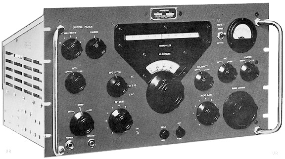
The Collins 51J-4
Collins 75S-1 (1958)
This receiver was designed for Amateur use, to transceive with the companion 32S-1 or KWS-1, and covers the ham bands and some other
optional parts of the HF spectrum in 14 x 200 kHz segments. It uses 12 valves.
The receiver covers the range 3.4 to 30 MHz, and uses a crystal controlled first conversion. Coverage is not continuous.
Some of the bands in my receiver have been changed
for short wave reception, and when I collected the receiver (at no cost) it was not working and most of the case screws were missing.
It's also a 110V receiver, so not the most convenient. This is the oldest receiver I have which uses a product detector, and SSB
reception is very good.
The 75S-1 has a tunable IF of about 3 - 3.2 MHz, following a preselector and band converter. The second IF is 455 kHz.
It has a single SSB mechanical filter,
switcheable BFO crystals for USB/LSB, with LC filters for AM. The vernier tuning dial is rather nice, but has rather slow tuning and
limited range per band. Reception is adequate, even on 10m. The preselector is annoying as the planetary drive slips at times.
Tube lineup: 6DC6 x2, 6U8 x3, 6BA6 x2, 6AT6, 6BF5, 6AU6.

The Collins 75S-1
Introduction
1920s - 1950s
1960s
1970s
1980s
1990 - today
Copyright � Murray Greenman 1997-2019.
All rights reserved. Contact the author before using any of this material.