My Receiver Collection
24 May 2019
Introduction
1920s - 1950s
1960s
1970s
1980s
1990 - today
Introduction - the 1970s
This is very much the era of analogue solid-state radios, and saw the introduction of the first synthesised receivers, even digital displays and digital synthesis.
Sony CRF-150 (1970)
This is a rather large 13-band short wave radio of the 'luggable' type (it weights 7 kg and is 340 x 275 x 144 mm).
Unfortunately my example must have spent most of its life in a cowshed, as it has significant corrosion and the main tuning
dials are rusted solid. Inside its wooden box is a marvel of dial cord and lots of mechanical assemblies. Both tuning
knobs have significant flywheels on the shafts. While the radio goes, at least on the AM band, you can't tune around at all.
The receiver has two IFs (1600 and 455 kHz), plus presumably a 10.7 IF for the FM band. Coverage is from 150 - 400 kHz,
530 to 1600 kHz, 1.6 to 4.5 MHz and 88 to 108 MHz, plus short wave. These bands are selected by front panel push-button switches.
The short wave bands have their own tuner,
with band change operated by a turret arrangement (knob on right side). This operates large nylon gears in the middle of the set,
the tuner band switch and the slide-rule dial scales.
There is no BFO and no ham band coverage. The short wave bands covered are 4.7 to 5.3, 5.8 to 6.4,
7.0 to 7.6, 9.5 to 10.1, 11.6 to 12.2, 15.0 to 15.6, 17.5 to 18.1, 21.4 to 22.0, and 25.5 to 26.1 MHz. The scales have
the short wave broadcasting bands marked, and the scale graduations are arranged in an interesting way: there is a row of markers
about 15 mm apart (spacing differs), which can be slid sideways by a small knob marked 'CALIBRATOR'. The marked frequencies
on each dial are limited to those which align with the markers!
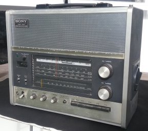
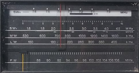
The Sony CR-150 (left)
and a detail of its dial (right).
The radio runs off six D cells, external 9V DC, or AC. The same unusual socket is used for both AC and DC supply, so there is
plenty of opportunity for expensive mistakes! The 220V/110V switch is internal, necessitating removal of the back panel for change-over.
There is an impressive 1200 mm long tilt-over telescopic antenna that pulls out on the top right, and a panel on the rear with screw
terminals for LW/MW, SW and FM antennae. There is an internal ferrite rod antenna for LW/MW.
Harris RF-505A (1971)
Designed as a very high quality general purpose receiver for commercial and military applications, the Harris RF-505A (NATO R.5075/GRR)
is a dual conversion receiver well suited to monitoring applications. They were used by the NZ military (mine came from the Air Force) and by the NZ Post Office as link receivers around the Pacific. I previously owned this radio around 2003 - 2008,
and it returned to the collection in 2014.
The earliest example I have of a fully synthesized radio, the RF-505A is in fully working order, and also the oldest receiver
in the collection with a VHF first IF.
The RF-505A is good looking, well laid out and simple to operate. It is completely 'knob tuned' (a row of decade
switches) in 100 Hz steps, so needs no display. There is an interpolating oscillator available for continuous
tuning between switched steps, achieved by pulling out the 1 kHz knob to activate it, then rotating the same knob to
control it. The interpolation range is ± 5 kHz.
All other oscillators in the receiver are referred to a very high performance ±1 in 108 5 MHz OCXO reference.
The frequency range is specified as 1.6 to 30 MHz (which is the range of the preselector), but with the preselector off,
the receiver will operate
down to below 100 kHz with reduced gain (sensitivity is 2 uV at 100 kHz). The first IF is 156 MHz, the second 500 kHz, using Collins mechanical filters.
The first mixer is a diode ring mixer, and there is no RF amplifier apart from a 2N5179 in the optional preselector.
Despite this the receiver achieves a sensitivity of 0.25 uV.
The second mixer is a dual gate FET. The receiver dynamic range is more than 125 dB.
The receiver is capable of ISB operation, so has two independent IF amplifiers, detectors and audio stages. There are
USB and LSB mechanical filters, one in each of the IFs, while one IF also has a 10kHz AM filter, the other a 500 Hz CW filter
(mine is missing this option).
While there is only one speaker amplifier, selectable between IF channels, there are two independent line-level audio outputs
and two internally lit 'S' meters!
My receiver recently had a major power supply failure, precipitated by a short in the Bulova 5 MHz crystal oven. I
replaced the oven with an ERC 5 MHz oven of similar vintage (from a Transit satellite navigation unit), and the receiver is
back in daily operation, with stability and accuracy to die for. The receiver has a rather nice rack cabinet, not shown
in the photograph.
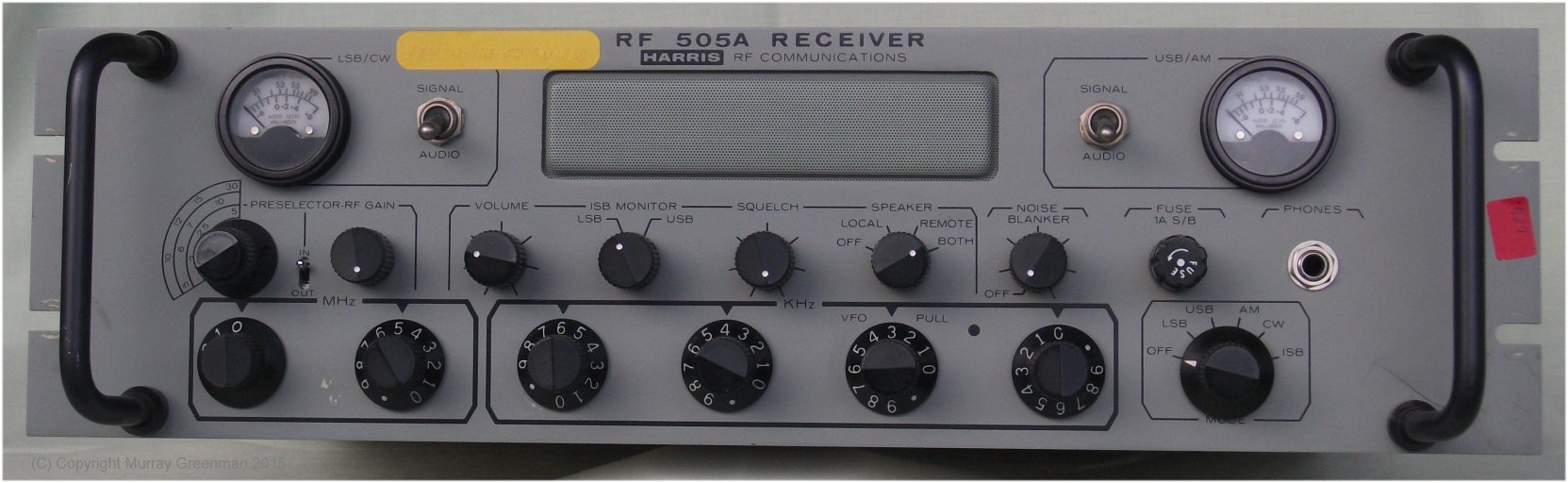
The knob-tuned Harris RF-505A.
Drake DSR-2 (1974)
This good looking receiver could have been one of the most expensive receivers in my collection.
It reportedly sold new for about US$3000, and was described at the time as a laboratory grade receiver,
although it looks more like something you'd use with the lounge stereo!
It operates from 10 kHz to 30 MHz, although the preselector only operates between 500 kHz and 10 MHz. The receiver operates
USB, LSB, CW, RTTY, FM and ISB, with a separate switch to select the detector and turn the BFO on and off.
This is my second-oldest synthesized radio, and tunes in 100 kHz steps with VFO
interpolation in 100 kHz bands. The three knobs in the upper centre select synthesizer 10s of MHz, MHz and 100s of kHz.
These switch shafts pass through the circuit boards, stacked one behind the other, and so select the front-end tuned circuits as well as the synthesizer settings.
The receiver has a frequency counter and direct readout of frequency to 100 Hz resolution using Nixie tubes. The
receiver is reasonably stable, and has excellent sensitivity. It also has a very good IF noise blanker. There are three LC filter bandwidths and mechanical filters for
USB and LSB, with separate IF amplifiers allowing ISB operation.
The receiver first mixer converts to 25 - 35 MHz or 15 - 25 MHz, depending on the range, and then the second mixer to 5 MHz,
then finally the third mixer to 50 kHz, using dual-gate FET mixers.
The receiver is one-owner, and looks new. Unfortunately this receiver has a fault in the synthesizer, but I have a second DSR-2 in working condition but more battered, and I intend to make one good receiver from the two.
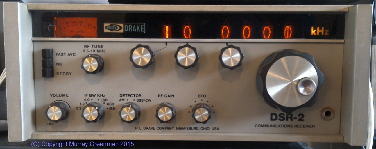
The Drake DSR-2 Receiver
Wandel & Goltermann SPM-12 (1974)
I own several Selective Level Meters, and while not exactly Communications Receivers, they are none-the-less useful for this purpose,
and of course give accurate signal strength measurements. The representative example here, the SMP-12, has digital locking and a 10 Hz resolution LED
digital display. It covers 0.2 kHz (yes, 200 Hz!) to 6 MHz, in just one range. The tuning dial operates a VCO using a multi-turn
potentiometer with an optional (pull on the knob) planetary reduction drive. The receiver also has a wideband mode. I also have the companion
PS-12 generator, and the two track together. I also have the SPM-60/PS-60 pair, which are similar, but cover to 18 MHz.
The receiver has sensitivity rarely matched by other receivers, -130 dBm, and selectable filters, 1.74 kHz, 500 Hz and 25 Hz.
It has no AM mode as such, but offers USB and LSB operation, with the choice of 1 kHz or 2 kHz BFO offset. The display reads the
received carrier frequency when the audio pitch is 1 kHz or 2 kHz respectively.
The first IF is 8 MHz, the second at 10 kHz, and the filters are Gaussian shaped LC types. The large level meter has 2 dB and 20 dB
scales, and the unit has a front-end stepped attenuator in 15 x 10 dB steps. The front-end arrangement allows for selectable
input impedance and balanced or unbalanced operation. There is no audio gain control, as all control is via the stepped attenuator.
The SPM-12 is one of the very best receivers for LF and low MF use. It will receive the Russian Alpha stations at 14 kHz easily when used
with an active antenna. (This is in New Zealand - range at least 15,000 km). There is no speaker-level audio amplifier, but the line-level audio output is handily on the front panel.
Stability of both frequency and level is excellent. The SPM-12 is rack mountable, can be battery operated, and weighs an impressive 17 kg.
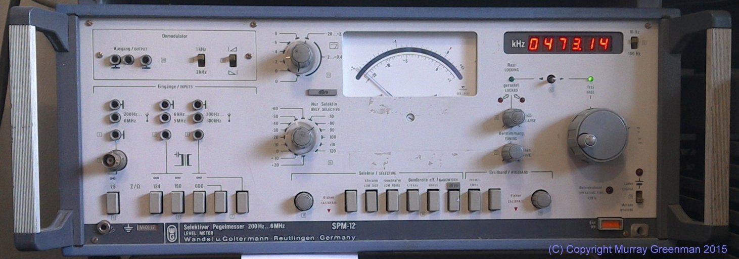
The W&G SPM-12 Selective Level Meter
Wandel & Goltermann SPM-60 (1977)
Another of my selective level meters, the SPM-60 covers 200 Hz to 18.6 MHz in one range. It has a 100 Hz
resolution neon display, using individual 7-segment tubes. The tuning dial operates a VCO using a multi-turn
potentiometer with an optional (pull on the knob) planetary reduction drive. I also have the companion PS-60 generator, and the two track together. The receiver includes the ability to frequency lock to the internal reference.
The receiver has excellent sensitivity and selectable filters, 1.74 kHz, 400 Hz and 24 Hz.
It has no AM mode, but offers USB and LSB operation, with the choice of 1 kHz or 2 kHz BFO offset. The display reads the
received carrier frequency when the audio pitch is 1 kHz or 2 kHz respectively.
The first IF is at 24 MHz, and the filters are Gaussian shaped LC types. The large level meter has 2 dB and 20 dB
scales, and the unit has a front-end stepped attenuator in 2 dB steps. The front-end arrangement allows for selectable
input impedance and balanced or unbalanced operation. There is no audio gain control, as all control is via the stepped attenuator.
The SPM-60 is rack mountable, can be battery operated, and weighs 20 kg. The dimensions are 478 x 199 mm, and 407 mm deep.
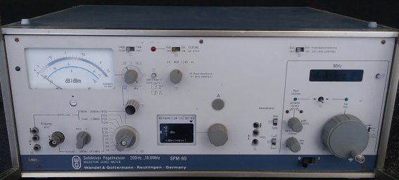
The W&G SPM-60 Selective Level Meter
Atlas 210X (1976)
Of course this is a transceiver, rather than a receiver, but I wanted to add one to the collection because of the milestone it
represents in the development of ham SSB receivers and transceivers. Quite a departure from previous SSB transceivers, the 210X
(and the 215X which has 160 metres and not 10 metres) uses a double balanced mixer, no RF amplifier, and a high-level IF amplifier
at 5520 kHz. The design offered (for the time) excellent cross-modulation and overload performance, and excellent low noise reception.
The Atlas made a great little mobile rig, as it is light and quite small. It weighs just 3.3 kg, and is 240 x 90 mm and 235 mm deep.
It packs quite a punch, 80 W PEP output, 50 W on 10 metres. Designed well before digital synthesis was affordable, the Atlas used
single conversion and a VFO which changed frequency for each band. Stability wasn't bad for the time, but not what we are used to today.
The history of the design is complicated. Herb Johnson W6QKI (founder of Swan) sold out to Cubic Corp, and started Atlas Radio
in 1974. The company became mired in financial and technical problems, and sales were delayed. The 210 and 215 models came along in 1976, and were very popular.
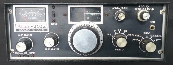
The Atlas 210X.
The technical development aspect is the most interesting. Herb Johnson hired Lester Earnshaw ZL1AAX (Kiwi developer of early
SSB adaptors, founder of Southcom International, and later designer of the Kachina) to design the radio.
Although I don't know the details, other Kiwis including Dennis Cobb of TV repeater fame were recruited to the design team. This same team was later
responsible for the 1987 Transworld TW100 (see further down this page), and the very advanced Kachina 505DSP (1997 - I'd love one!). Look at the schematics of these radios, and you'll recognise similarities - for example, no RF amp, double-balanced mixers and high level IF amplifiers.
Yaesu FRG-7 (1976 - 1980)
This is probably the best known of the Wadley Loop technology receivers, although perhaps because it is reasonably easy to operate,
many don't realise that's what it is. The FRG-7 has a well desrved reputation: it is solidly built, reliable and reasonably
sensitive. It covers 500 kHz to 30 MHz, and is triple conversion. The first IF is 55 MHz, the second tunable IF is 3 to 2 MHz,
and the third IF is 455 kHz. The Wadley Loop synthesis applies to the first mixer, with stepped harmonics from 55.5 to 84.5 MHz.
My FRG-7 was a gift from a Southland ham, and is in showroom condition. It operates like a new receiver too. The FRG-7 is not small, 340 mm x 153 mm x 285 mm deep, and weighs 7 kg. It is mains operated, but can be battery operated (eight internal D cells in an
optional holder) or from 12V DC.
It operates AM, LSB, USB or CW, and has an AM noise blanker option. Tuning with the main dial is a bit fierce, but this version
(a later model) has a fine tune control lacking on the early model. There is a band switch and two variable capacitor tuning controls
(Preselector and MHz, the harmonic selector), in addition to the main tuning, which has an edge-view drum tuning display covering a range of 1 MHz. So there are in total five separate frequency-related controls!
The FRG-7 has plenty of good sounding audio. The Preselector, MHz and main tuning displays are back lit (lamps). The S-meter is
also back lit. There is one red LED, which is used to indicate when the synthesiser loses lock. Its operation seems to be the
reverse of what is intuitive. It should be labelled 'Loss of Lock' rather than 'Lock'.
The FRG-7 and the FRG-7000 (below) are two of a select group of 'left-hand-drive' receivers, easily operated by
left-handed operators. Most receivers are strongly biassed to 'right-hand-drive', as a quick check on this web page will affirm.
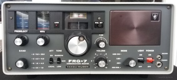
The Yaesu FRG-7 Receiver
Yaesu FR-101D (1978)
This FR-101D is the later version with vacuum flourescent digital readout. The individual digit tubes are large and clear. Some
of these receivers had red LED displays, and earlier models had only an analogue display. The tuning direction is the reverse
of what's usual these days - tuning clockwise moves the receiver down!
The Yaesu FR-101D Receiver
Although mine is ham-bands only (160, 80, 40, 20, 15, 10 m), the receiver has a 21 position band switch, and markings for short wave broadcast bands and several optional bands. Bands are added by fitting crystals and minor alignment. The receiver is in reasonable
condition and works well. Mine is also fitted with the optional 2 metre converter, but not with the FM module, which rather
reflects it's vintage, before VHF FM became standard. The receiver has an SSB filter and wide and narrow AM modes, but no
additional filters, meaning these modes rely on the roofing filter for bandwidth.
The receiver is double conversion, with crystal controlled first conversion and a 3180 kHz second IF. The first IF is tuned as you
tune the main tuning dial. A noise blanker is fitted, which includes the 3180 kHz roofing filter, which has 20 kHz bandwidth.
There is a very effective preselector, with three ganged, slug-tuned coils, in the Collins manner.
There is provision for four crystal controlled channels and for both 6- and 2-metre converters, which have separate antenna inputs.
The receiver operates on the 10 metre band when operating on VHF. To accomodate the complete VHF bands, the converters have two
conversion crystals 1 MHz apart.
The receiver dimensions are 340 x 153 mm, and 285 mm deep. It weighs 9 kg. My receiver is working (ham bands only)
and is in reasonable condition. It cost me $5.
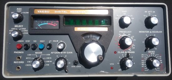
Yaesu FRG-7000 (1977 - 1980)
This is my only other Wadley Loop receiver. It's a bit battered, but runs well. I keep it in the garage to monitor test transmissions.
A successor to the famous FRG-7 'frog', the 7000 is a typical 'short wave' receiver, with clock, timer and recorder control features.
The receiver covers 250 kHz to 30 MHz in 30 selectable band segments.
Band selection has two facets, a BAND switch which selects the Preselector range (5 bands), and a MHz control which selects the necessary reference harmonic for the required band. The MHz control has no tuning dial (as in the FRG-7), but instead indicates
where you are tuned using the MHz digits of the red LED frequency display.
Frequency resolution is to 1 kHz, and reads in a bizarre manner off the ends of the VFO range.
Band selection is not initially intuitive, but is effective, provided you watch the UNLOCK indicator.
There is a band-switched preselector, which is impressively sharp, but you don't hear anything unless you're close to tuned.
The main tuning operates a VFO and is continuous in 1 MHz bands.
The first IF is tunable 54 - 55 MHz, using a Wadley Loop scheme. The second IF is tunable 2 - 3 MHz, tuned by the VFO. The third IF
is 455 kHz. The frequency counter measures the first and second local oscillators to calculate the operating frequency display.
The FRG-7000 operates AM, USB, LSB, and CW. The bandwidth is 3kHz (SSB/CW) or 6 kHz (AM).
There are 50 Ohm and random wire (0.25 - 1.6 MHz) antenna options. The receiver looks impressive, but is a pig to use
(five separate controls to tune in a station!), and stability
is modest. Definitely not for beginners, as getting the band selection and preselector correct are both a bit tricky. My receiver
suffers from disuse, with intermittent contacts on the Band and Mode switches. Audio quality is good, and there's plenty of it.
The receiver weighs 7 kg and is 360 mm wide, 125 mm high and 295 mm deep. It has a metal case, and a solid plastic front panel,
but is let down by a flimsy plastic bezel surrounding the front panel. Mine looks like it's been chewed!
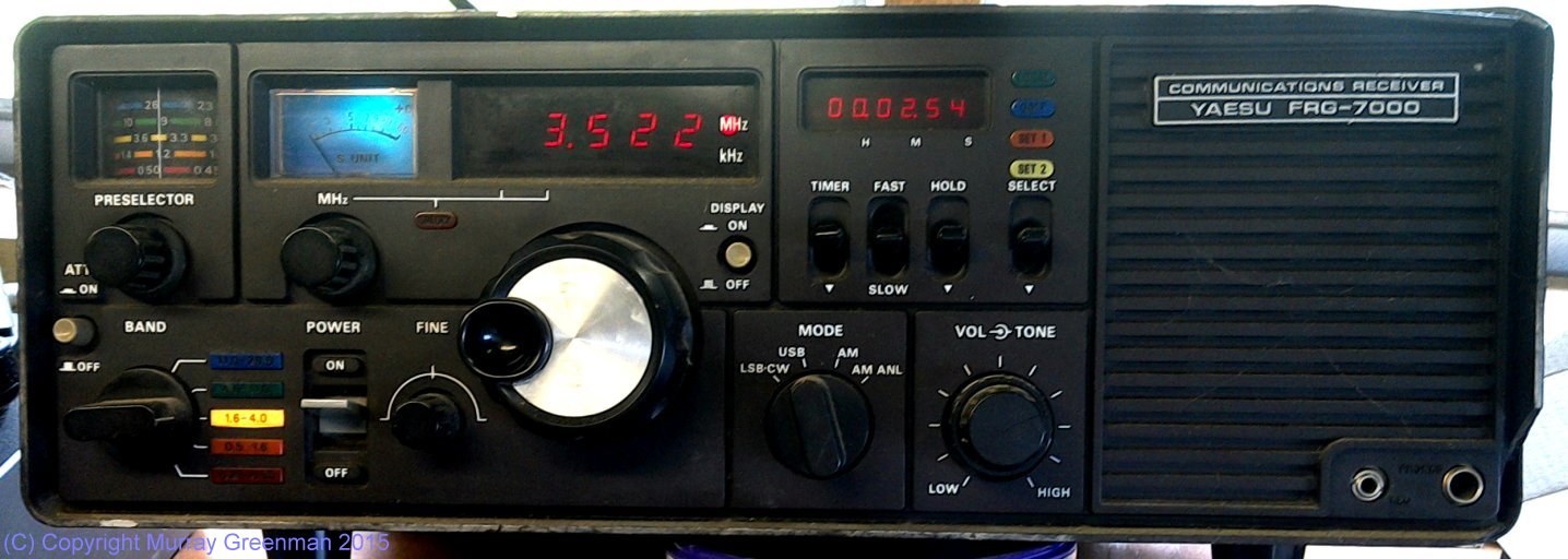
The Yaesu FRG-7000 Receiver
RACAL RA6790/GM (1979)
Designed as a professional monitoring receiver, the RA6790/GM is one of the best, even today. All oscillators are referred to a single
oven-controlled reference, or an external 1 MHz reference source can be used. Not small, the receiver is rack-width, 450 mm deep, and weighs 13.5 kg.
The receiver nominally covers 500 kHz to 30 MHz, although it will operate quite well down to 10 kHz with appropriate firmware, although there
are no bandpass filters below 500 kHz in this model.
The receiver display is via two LCD units, and resolution is to 1 Hz (the synthesizer also has 1 Hz steps resolution). There are two membrane-type
keypads, which have remained reliable.
The first IF is 40.455 MHz, and the second IF 455 kHz. The first mixer uses double-balanced monolithic junction FETs, and there is no RF amp. Quite a range of
filters, crystal and mechanical, are available, and five additional filters can be fitted at any one time. The receiver measures its own filters
on start-up and so knows what is fitted. Optional filters range from 300 Hz to 20 kHz bandwidth, and are symmetrical. The USB and LSB filters are
fixed (not replacable) asymmetrical crystal filters. My receiver does not have the ISB option.
This is the oldest micro-controller operated receiver in my collection, and unfortunately at present it has an obscure controller fault.
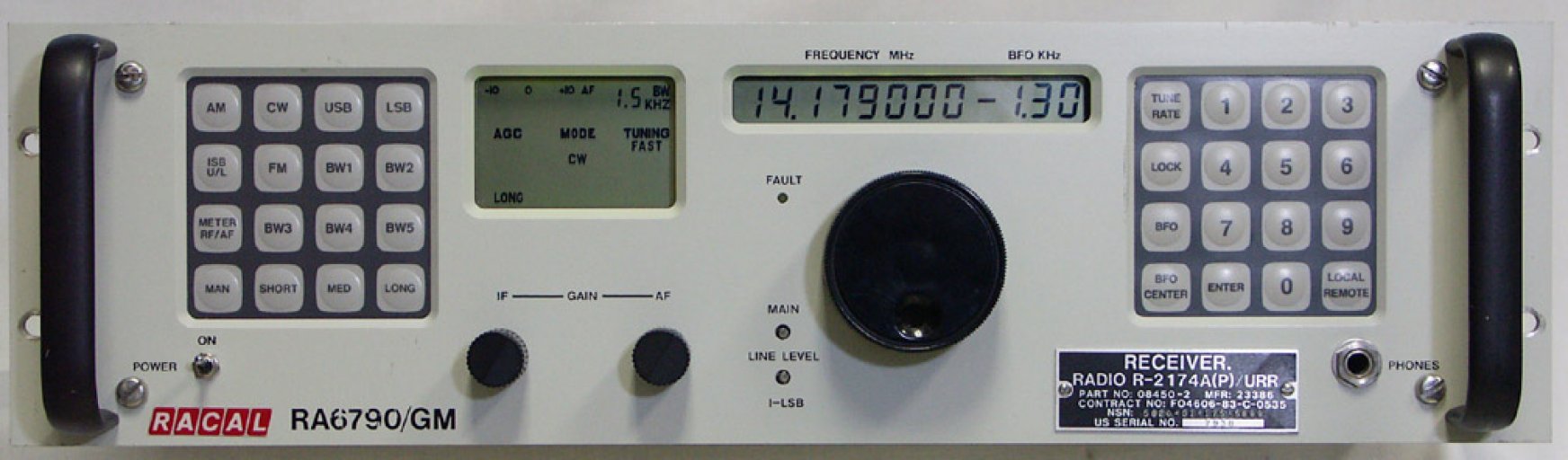
The RACAL RA6790/GM receiver
Eddystone 40A (1979)
This is primarily a Noise Measuring Receiver. While it has AGC as an option, its not a comfortable receiver to listen to, as it has a very
small speaker, is easily overloaded, and has only a wide filter designed for standardized CISPR noise measurement.
The receiver covers 130 kHz to 32 MHz in eight bands, with a gap around the IF frequency. It uses a slide-rule dial, with scales that rotate
as the band switch is changed. A single conversion design, the IF is 1.75 MHz. The bandwidth is 9 kHz using a Gaussian filter which
meets CISPR requirements. The detector time-constants and meter operation are also to CISPR requirements. There is even a BFO, although it
is of limited use. Tuning is via a dial cord, and is smooth but rather slow. It takes several minutes to tune from one end of each band
to the other.
The 40A operates from an internal 9V battery pack (which I don't have), external 9V via a rear-panel socket,
or the optional 230V battery eliminator (which I have).
It has lighting behind the dial and the meter, which can be operated from a front panel push-and-hold switch.
Intended for noise and interference measurement, the receiver has a remarkably flexible range of input options. It will operate from external
whip or wire antennae, from a front-panel BNC input or from internal 'loop' (ferrite rod) antennae, one for each band, which tune with the
main tuning. Because the case is fibreglass, these internal antennae are very effective, and also quite directive, so useful for direction finding.
The receiver includes a pulse noise source which is used to calibrate the receiver gain at the operating frequency, since in this type of receiver,
gain is not flat over the frequency range or between bands. It will measure noise or
carrier level to within 1dB, using stepped 1dB and 10dB rotary attenuators at the front end.
My 40A receiver is missing the metal front trim, the carrying handle and the cover, but it works just fine, and is highly useful
for locating interference and making field measurements. I have made it a rear blanking panel (to cover the battery pack/eliminator hole, and
supply one of the rear feet which is normally on the power pack!),
and a DC power cable for use with a 7AH 12V gel-cell battery.
The receiver is 'luggable': it weighs 10kg and is 385 mm wide, 161 mm high and 358 mm deep. It is a fine receiver, a pleasure to use,
ruggedly built and well designed. Unfortunately the fibreglass case has not well survived 35 years of field use.
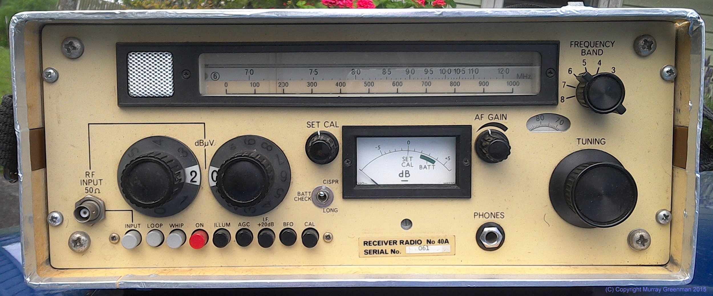
The Eddystone 40A Noise Measuring Set
Kenwood R-1000 (1979 - 1985)
Quite a contrast to the Wadley Loop receivers of an earlier generation, the R-1000 heralded an era of multi-loop PLL synthesis
receivers, using a VFO to interpolate between 1 MHz steps. A small processor is used to read the band switch, select the PLL settings,
the bandpass filters and operate the frequency counter and display. This is a similar arrangement to the TS-120S and TS-130S
transceivers of the same era.
With just two frequency related controls, Band and Tuning, the R-1000 is exceptionally easy to use. Not quite as stable as we've
come to expect these days, nevertheless the receiver is adequately stable for SSB after warmup, although tuning requires care.
The receiver operates from 200 kHz to 30 MHz.
The receiver employs PLL synthesis in two steps, using a common reference. It uses double conversion. The first IF is 48 MHz and the second 455 kHz, where there are wide (12 kHz) and narrow (6 kHz) AM filters, and a 2.7 kHz SSB filter. The BFO injection is derived from independent
crystal oscillators, and results in the digital display
reading 1.5 kHz in error (opposite directions) on USB and LSB. The display indicates in 1 kHz steps.
As is common in 'short wave' receivers of the time, the R-1000 includes timer and tape recorder functions. There is a useful
four-step RF attenuator. The loudspeaker is in the top cover.
I bought an R-1000 new in about 1981, and later regretted selling it. The receiver I have now is of
similar vintage, and shows its age with iffy switches and a noisy volume control, but otherwise goes fine and looks good.
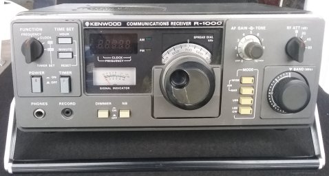
The Kenwood R-1000 Receiver
Introduction
1920s - 1950s
1960s
1970s
1980s
1990 - today
Copyright � Murray Greenman 1997-2019.
All rights reserved. Contact the author before using any of this material.