Portable Radio TX Spurious Tests
Today's activity builds on recent high-VSWR load measurements and prepares for transmitter system level testing of two-way portable radios -- with checking for spurious outputs when the radio is operating into other than a nominal 50 Ohm load. In the past, I have seen radios transmitting into non-50 Ohm loads show 1) harmonic levels exceeding FCC limits, and 2) the transmitter begins generating spurious outputs (xmas-tree or munge) where the spectrum breaks into oscillation when the antenna is loaded by a hand or placed close to a human body.
These tests are different from a standard radio transmitter check where RF power level and spectral quality is measured while terminated into a nominal 50 Ohm load. Instead these tests use a sampling port of a directional coupler to connect an observation RF Spectrum Analyzer while sending the TX high power signal down the main line into a purposely mis-matched termination. This condition reflects some/most of the transmitter's signal sending it back to the transmitter - resulting in high standing waves on the line (with varying phase and voltage levels). Will the transmitter behave properly with a mis-match applied? Determining that is the purpose of these tests...
The frequency coverage of the directional couplers influences how the test is setup and executed. Using off the shelf Narda couplers, two setups are needed for high VSWR tests, one for VHF and a second for UHF. Adding these to the broad-band in-line direct connect attenuator setup for nominal 50 Ohm termination, yields three setups total for transmiter power, spectrum, and spurious performance. (Nominal load transmitter tests will follow in a later post.)
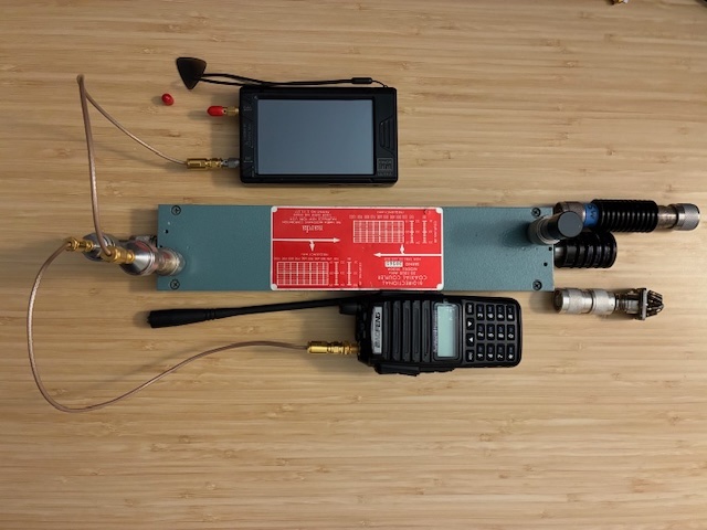
A Narda 3020A directional coupler is the main component for the VHF frequency tests. The Device Under Test (DUT) transmitter signal is connected into the main/through line leading to a load termination at the far end. The far end termination is a 50 Ohm termination (calibration or nominal test), a 10:1 VSWR termination, or a 3:1 VSWR termination. A 20 dB N-connector attenuator is used on the forward sample port to further attenuate the signal to the TinySA-Ultra RF Spectrum Analyzer. Combined with the 3020A's ~23.5 dB coupling factor, this yields about 43 dB of attenuation in that path. A Narda 378 NM 50 Ohm termination is applied to the reverse (REV) port on the coupler. The VHF test configuration with Baofeng UV-82 radio is shown below. This setup can reasonably measure spurious signals from 50 MHz up to 1000 MHz.
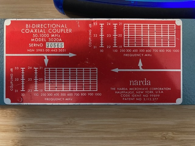
A challenge using the 3020A coupler in the VHF band (fundamental at 146.52 MHz) is that the coupling factor is not linear below around 250 MHz. This introduces measured marker level inaccuracies between the fundamental and the harmonics present. This means that using a coupler's sample port is not necessarily the best choice measuring harmonic levels except for the case when seeking signs of oscillation (and paying less attention to the absolute level of any signals present on the analyzer). The coupler has sample port calibration marks on the label to allow quick determination of the coupling factors at select frequencies (32.5 dB @ 50 MHz, 23.6 @ 150 MHz, and around 20 dB at select frequencies from 250 to 1000 MHz). A close up of the 3020A label is shown below.
Below is a NanoVNA-H4 measurement of the non-linear coupling factor on the 3020A sample port (with the included 20 dB add-on attenuator present). The ~4.3 dB decrease in loss between the fundamental and the third harmonic means that the measured harmonic levels will be reported as 4.3 dB higher (relative to the fundamental) than the transmitter's signal is measured at. This is not a problem when just looking for spurious signals, but likely confusing if trying to closely measure harmonics levels relative to the transmitter's signal level. Marker 1 is at 146.52 MHz. Marker 2 is at 446.00 MHz.
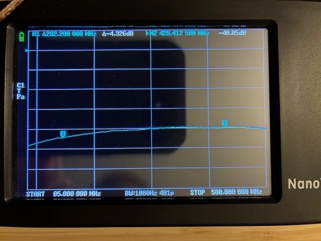
Again, coupler sample port non-linearity is primarly a VHF transmitter test issue, and not expected to be a significant issue for UHF tests.
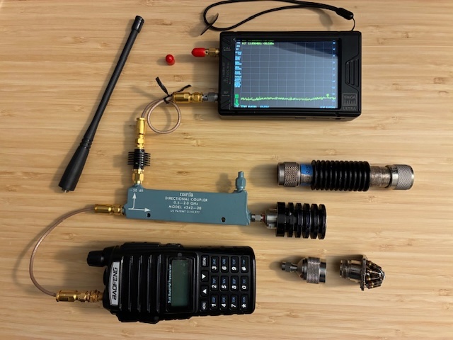
A Narda 4242-20 directional coupler is the main component for the UHF frequency tests. Note in the picture below that this coupler is much smaller than the 3020A used for VHF tests. (Directional coupler size varies with frequency coverage - lower frequencies = larger coupler and higher frequency = smaller coupler). The Device Under Test (DUT) transmitter signal is connected into the main/through line leading to a load termination at the far end. The far end termination is a 50 Ohm termination (calibration or nominal test), a 10:1 VSWR termination, or a 3:1 VSWR termination. A MCL VAT-20W2+ 20 dB SMA-connector attenuator is used on the forward sample port to further attenuate the signal to the TinySA-Ultra RF Spectrum Analyzer. Combined with the 4242's ~20 dB coupling factor, this yields about 40 dB of attenuation in that path. A built-in 50 Ohm termination is at the reverse (REV) port on the coupler. The UHF test configuration with Baofeng UV-82 radio is shown below. This setup can reasonably accurately measure fundamental and all harmonics up to 2,000 MHz.
The TinySA-Ultra RF spectrum analyzer has built-in test modes to measure transmitter harmonics - measuring fundamental and visible harmonics with dBc (relative to fundamental power level) markers applied. This simplifies making TX harmonics tests, but does not provide the broad frequency coverage potentially needed to see non-harmonic spurious outputs. For spurious signal checks, this requires using the TinySA-Ultra setup for a separate test covering from below the fundamental up to about four times the fundamental (4th harmonic).
A trial run test for the Baofeng UV-82 transmitting on low power on 146.52 MHz into a nominal 50 Ohm termination yielded this spectral result:
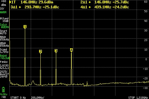
The above capture does not include correction for the 3020A non-linear coupling factor and suffers in accuracy in that harmonics appear to be higher by ~4.3 dB than they actually are...
The external gain of the TinySA-Ultra was set to -43.5 dB (the approximate coupling factor of the sampled path) such that the marker at 1T shows the UV-82 output of about +29.6 dBm (approximately 1 watt), not incuding the loss of the cable from the radio to the coupler input. The exact radio output power is not as important as the relative level of the three harmonics (2 to 4). Will be taking a closer look at the UV-82 harmonic levels in later measurements (as well as measuring other on-hand radios).
Let's wrap up this post with a quick measurement of a direct attenuated test setup that may be used for transmitter power level measurement and accurate 50 Ohm terminated harmonic level measurements. This is a JFW Industries 50FH-020-50, 50W capable 20 dB, 2 GHz RF attenuator that is much larger than needed for portable radio (< 10W) transmitter tests. Using the NanoVNA-H4 vector network anayzer to measure S21, insertion loss, is a quick test with just a few cables and a simple pre-test calibration.
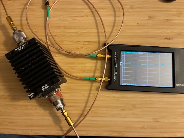
The NanoVNA measurement showed essentially flat 20 dB insertion loss up to 500 MHz. Plan to repeat this test up to 1.5 GHz using a smaller Narda 766-20 (4GHz, 20dB, 20W) RF attenuator as part of future nominal load testing.
Will update this post when additional data is available.
Author photos taken with an iPhone-16e.