High VSWR Loads
Preparing for some transmitter testing of two-way portable radio products and checking for spurious outputs when the radio is operating into other than a nominal 50 Ohm load. Have experience testing radios where transmitting into non-50 Ohm loads resulted in 1) harmonic levels rising and exceeding FCC limits, and/or 2) the transmitter begins generating spurious outputs (xmas-tree or munge) where the radio breaks into oscillation when the antenna is loaded by a hand or placed close to a human body.
These tests are different from a standard transmitter check where the RF power level and spectral quality is measured while terminated into a nominal 50 Ohm load. Instead these tests use a sampling port of a directional coupler to connect an observation RF Spectrum Analyzer while sending the TX high power signal down the main line into a purposely mis-matched termination. This condition reflects some/most of the transmitter's signal sending it back to the transmitter - resulting in high standing waves on the line (with varying phase and voltage levels). This post examines the on-hand VSWR test loads to determine their suitability for use in future tests.
Three load types are available in the lab (10:1 VSWR, 3:1 VSWR, and nominal 50 Ohm termination / dummy-load).
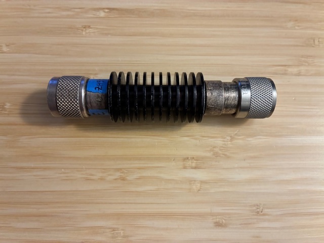
Two types of 10:1 VSWR loads were tested. Both were DIY - constructed in the distant past, with one being a 3 resistor in parallel version and the second consisting of 11 resistors in parallel to make up the load. Both target 5 Ohms nominal resistance to yield a 10:1 VSWR in a 50 Ohm system. One 3:1 VSWR load was also tested (details below).
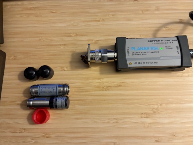
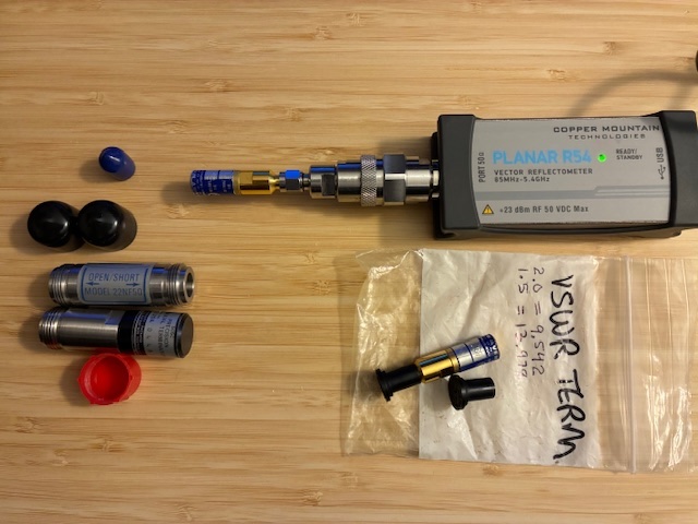
A vector impedance probe (Copper Mountain Technologies R54) was used to measure the impedance of the loads over the 85 to 450 MHz band with markers set at 146 and 446 MHz. The probe was calibrated before the tests using Wiltron and Agilent N-Female calibration standards. The photo below shows the R54 vector probe with one of the 10:1 VSWR loads attached and the calibration Wiltron 22NF50 Open/Short and Agilent 909C OPT 013 Termination to the lower left of the probe. Smith Chart display was used to confirm the calibration status (short = dot on left side of chart, open = dot on right side of chart, and term yielding a dot in the center of the chart).
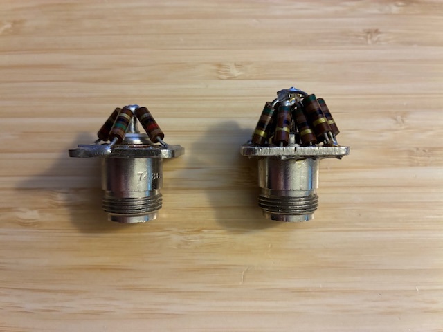
The two 10:1 VSWR loads are constructed on N-Female jacks (UG58A/U) with a few holes drilled into the connector flange to properly terminate the ends of the 1/2 watt resistors to the coaxial shield side. One of the loads has three resistors (A, left) and the second has 11 resistors (B, right), all connected in parallel to ground.
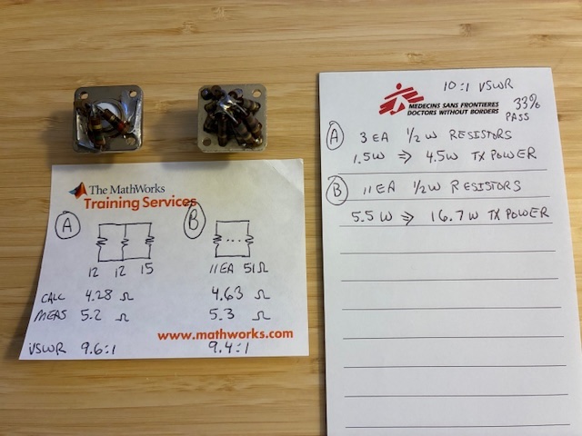
The notes below show the makeup of the 10:1 loads, with simple resistance measurements and estimates as to their resultant VSWR performance and power handling capbility. Load "B" has over three times the power handling capability of load "A".
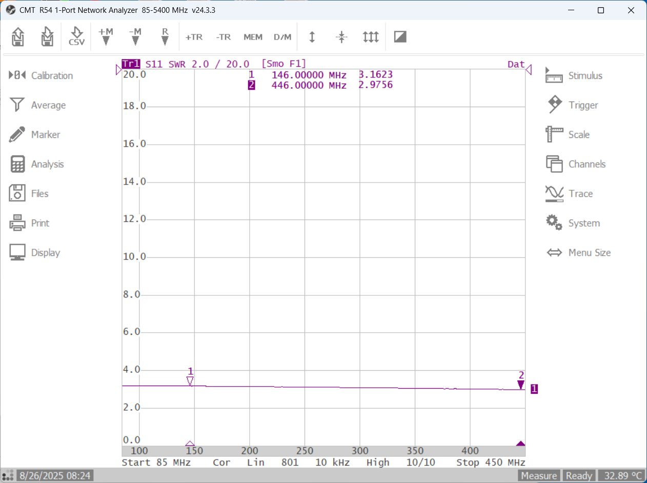
Connecting Load A (3 resistors) to the vector probe yields this VSWR plot. It's close to 10:1 with some upslope to the VSWR curve as frequency increases.
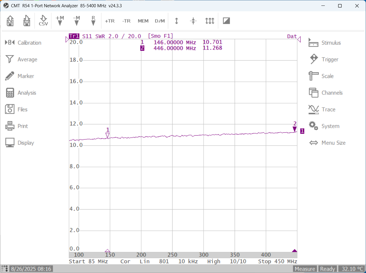
Connecting Load B (11 resistors) to the vector probe yields this VSWR plot. It's even closer to 10:1 with a very flat response.
From these tests, the 11 resistor version (B) of the 10:1 load is a clear choice to use for future tests with both flat VSWR performance and higher power handling capability.
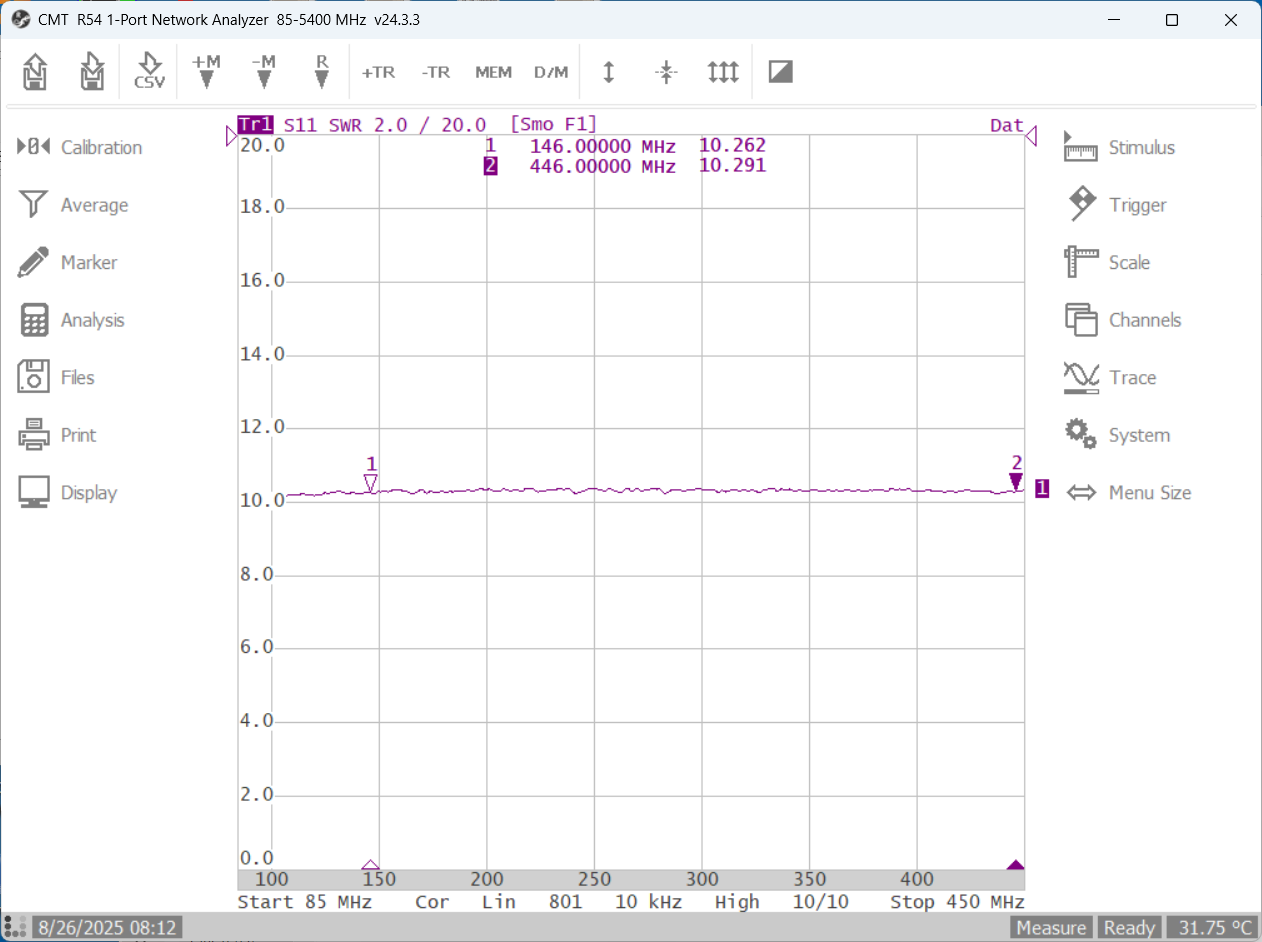
Next, the 3:1 VSWR load was measured. This consists of a Microlab/FXR 6 dB pad with Narda N-Male shorted end applied, yielding 3:1 VSWR, 75% pass, 25% reflect. This is a 15W rated attenuator, covering up to 4 GHz.
A precision N-Female to N-Female was used to connect the 3:1 load to the vector probe's N-Male test port.
With a 15 watt attenuator rating, this load can be safely used for portable radio transmitter load tests. The load is reasonably flat over the VHF and UHF bands.
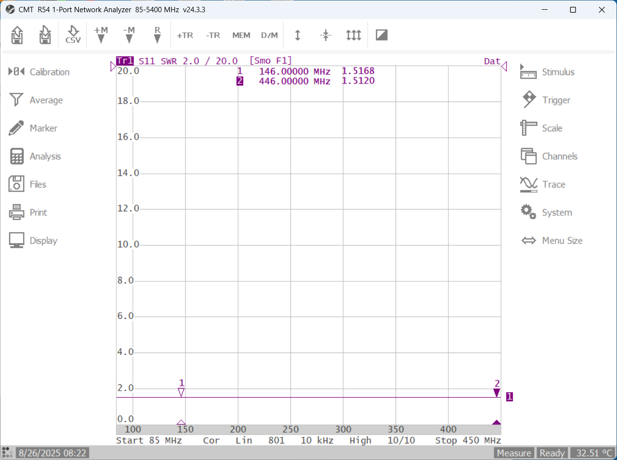
As part of the VSWR load verification tests, two Maury Microwave precision VSWR loads were measured to confirm test system calibration. Their VSWR values are 2:1 and 1.5:1 and both utilize APC-3.5 female connectors. A Narda precision RF adapter (N-F to SMA-M) was added to allow testing these devices.
Both VSWR standards appear to be spot-on, with little error observed using this test system. Read the marker values below for confirmation that all appears well with these tests...

Summary: Completed measurements on three high VSWR loads to determine suitability for use in future portable radio transmitter stability/spurious tests. Now have both 10:1 and 3:1 VSWR loads identified and tested for this use. Verified the RF impedance and VSWR test system using precision VSWR loads to ensure usable (correct) data was output.
With high-VSWR test loads identified and tested, it is time to identify test setups for VHF and UHF portable radios using these loads. The next post begins this process.
Almost ready for high-VSWR transmitter load tests!
Author photos taken with an iPhone-16e.