2.4 GHz Pluto RF Equipment
With thoughts of ultimately ending up with a 8 band SDR transceiver, the reality of actually building such a complex radio quickly points to starting with a simple one-band version instead. This post covers setting up a single-band (2.4 GHz) radio system and focuses on just the RF and antenna components (RF Equipment, or RFE) for the radio.
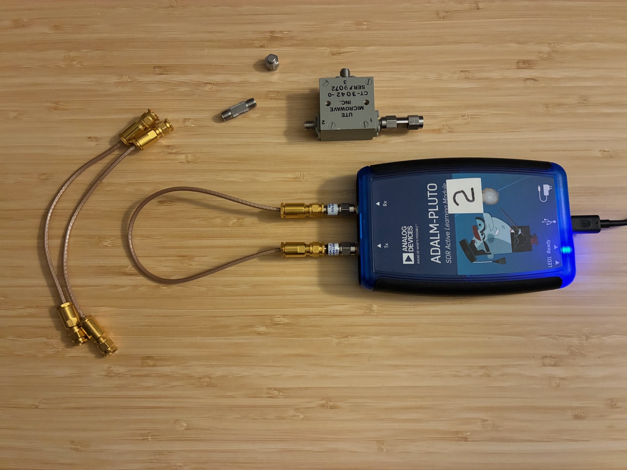
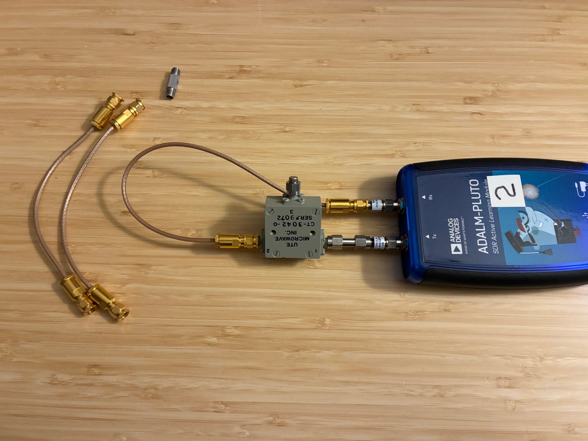
While most if not nearly all SDR radio examples utilize a transmit-receive switch, this simple get-started version uses instead a RF circulator to greatly simplify the RFE. Below are the two SDR radios shown with circulators and antennas attached.

The line-up from the Pluto SDR TX port is:
- SMA-M to SMA-M adapter
- UTE Microwave Circulator CT3042-0 (2-4 GHz) Port 1 (TX in)
- Circulator Port 2 (Antenna connection)
- SMA-M to SMA-M adapter
- SMA-F to N-M adapter
- TECOM 505036D 2.4 to 2.485 GHz Colinear Antenna
The setup also uses a short SMA-M to SMA-M coaxial cable from the circulator Port 3 (RX output) back to the Pluto RX port. This connects the SDR receiver up to the antenna.
The TECOM antennas were measured to ensure they were working (and resonant) in the 2.4 GHz WiFi band. Below is a VSWR chart measured using the Copper Mountain Technologies R54 vector impedance probe.
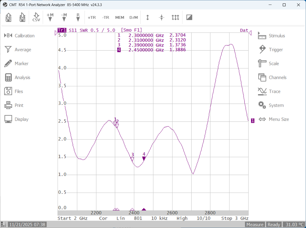
Markers 3 and 4 point to the band portions likely to be used with this setup (2.39 to 2.45 GHz). With a VSWR under 1.5:1 in this band, these surplus colinear antennas are looking pretty good.
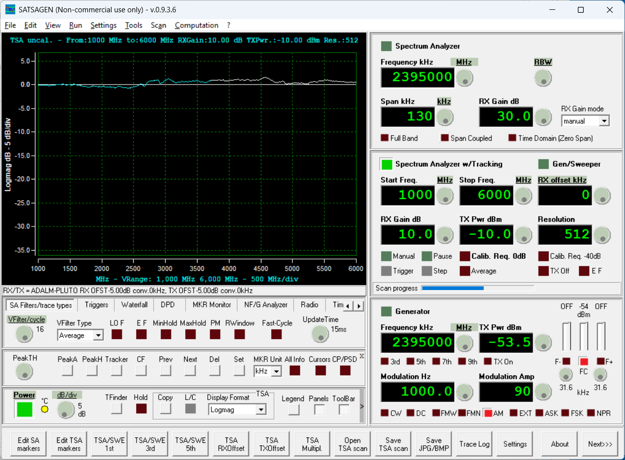
Next, the UTE Microwave circulators were looked at. For this test, one of the Pluto SDR's was connected to the PC and controlled via SATSAGEN software to create a 2-port scalar network analyzer. To begin, a calibration trace was established (minimum loss from TX to RX ports on the Pluto).
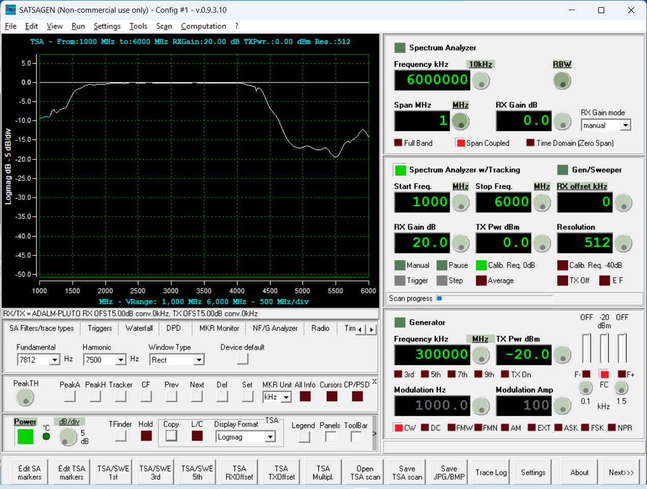
The before calibration response is below. Not too bad, but can be closer to zero with calibration.
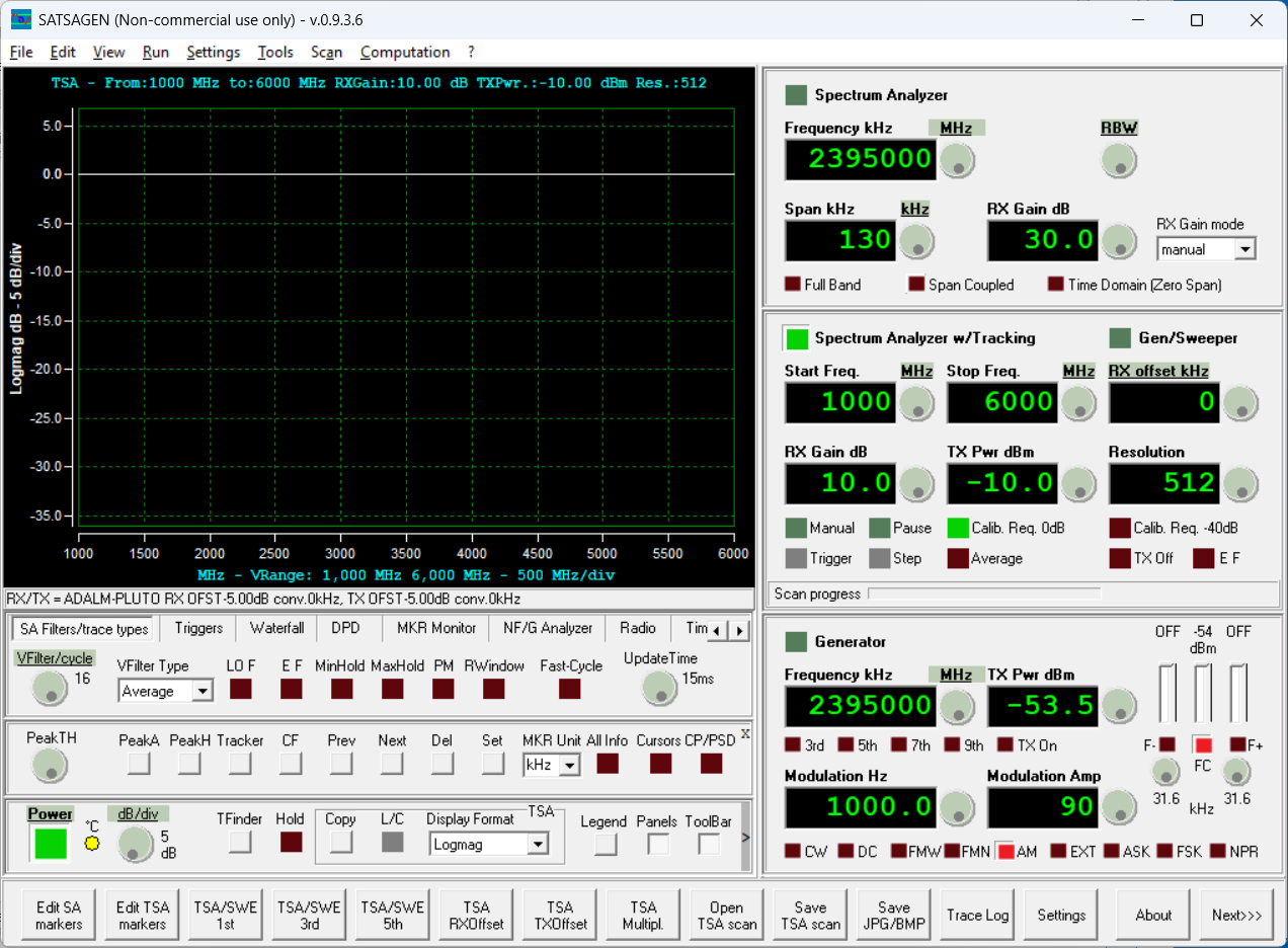
After calibration is below. Looking pretty good (measurement trace is right on the zero line).
The loop-back calibration setup is below.
Installed the circulator with Pluto TX connected to circulator Port 1 and Port 2 connected back to the Pluto RX port. This measures through insertion loss of the circulator in the forward direction.
Below is the SATSAGEN trace showing the forward insertion loss of the circulator (P1 to P2). A termination is applied to P3 of the circulator (RX port).

The circulator shows low insertion loss for the transmitter's power from P1 to P2 over the 2 to 4 GHz band. This appears to be under 1 dB of insertion loss (measurement accuracy is close enough for the moment).
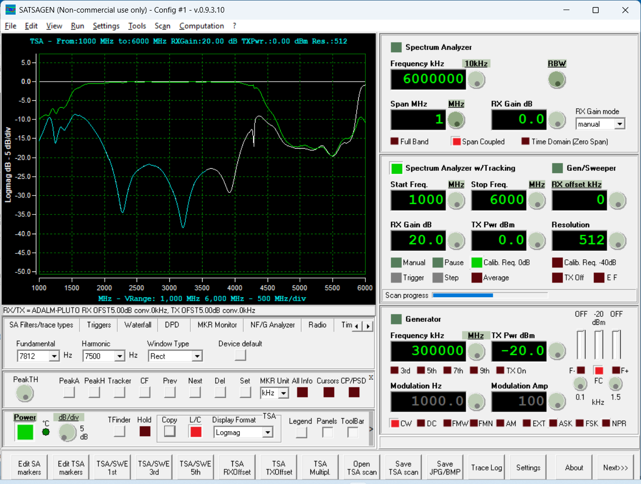
If we reverse the two connections and inject a signal at P2 while monitoring at P1, we are measuring the reverse isolation of the circulator. This yields the lower trace in the screen capture below. The difference between the top trace and the lower trace is the isolation of the device (approximately 20 dB or more between 2 and 4 GHz).
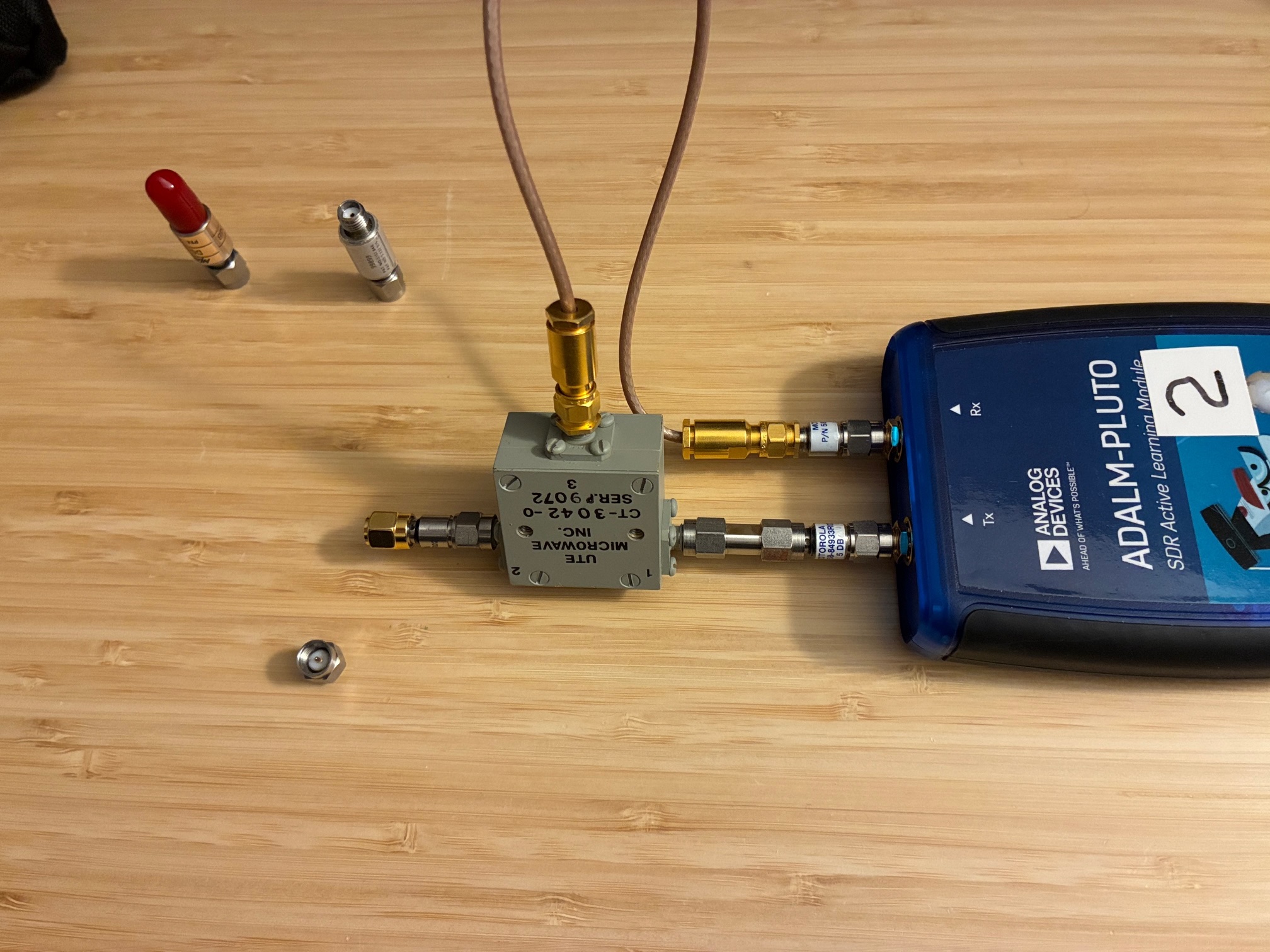
The next test looks at the RX insertion loss from the antenna connection to the SDR RX port. For this test, we connect Pluto TX to circulator Port 1 and connect circulator Port 3 to the Pluto RX connection with a 50 Ohm termination on circulator Port 2. A photo of the setup is below. I expect to see essentially the same low-loss curve in the 2-4 GHz band.

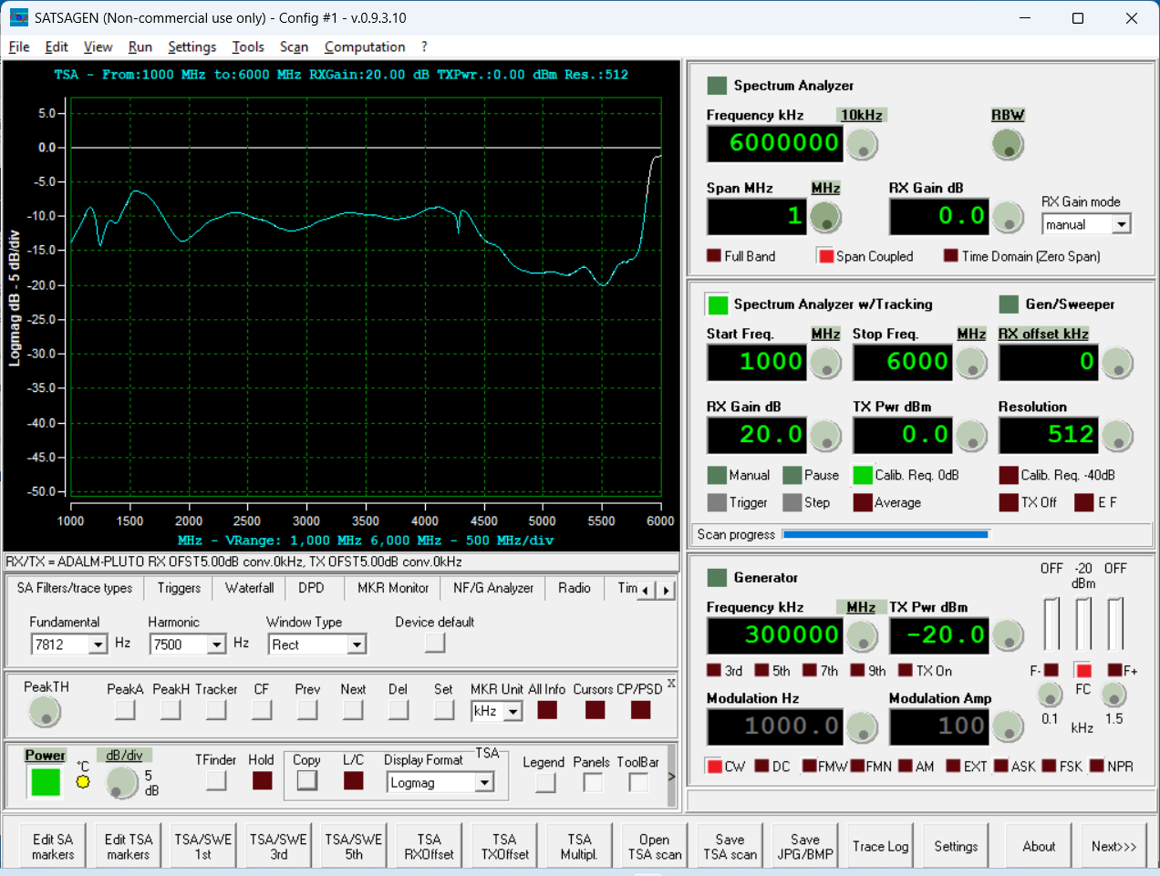
SATSAGEN measurement confirms that the loss in the 2-4 GHz band is low.
Note that this is for a perfectly terminated (very low VSWR) antenna connected to the circulator. What happens if the antenna is poorly matched and presents a higher VSWR to the circulator? (Theory predicts that decreasing the return loss of the antenna "termination" and increasing the antenna's VSWR to the Pluto's TX power will reflect that power back through to the circulator, and raise the TX power level received at the Pluto's RX port via circulator port 2.)
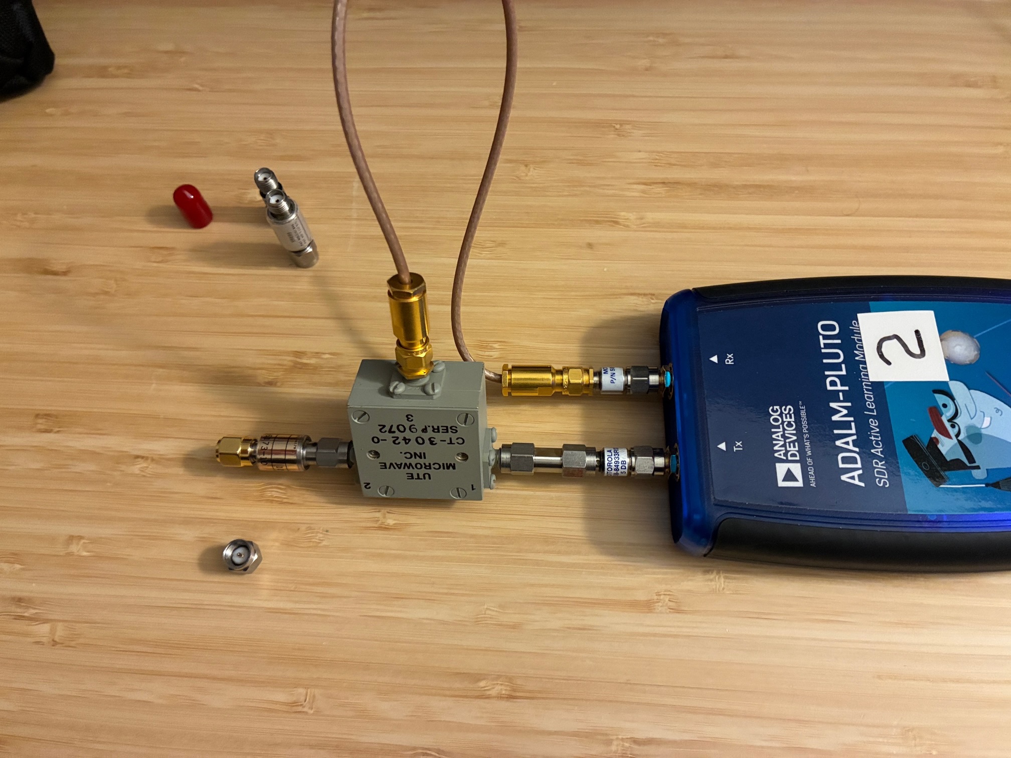
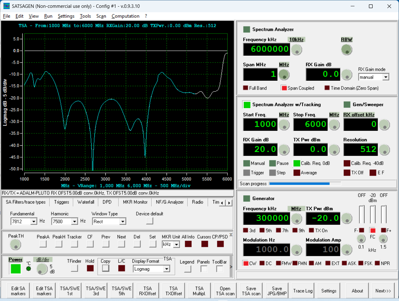
For the next tests, this relationship is confirmed using a series of non-perfect loads attached to the antenna port of the circulator. Below is an isolation measurement between the SDR TX port and the RX port with a short applied to the circulator antenna connection. This is effectively the worst case situation for a failing antenna.
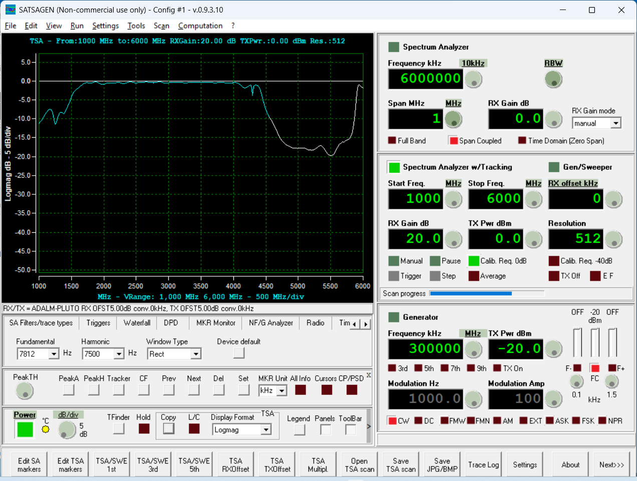
The measurement confirms that for a "bad" or missing antenna, that all of the Pluto TX power is reflected through the circulator and appears at the circulator RX port (connected to the Pluto RX port via the short RF cable). For a higher power system, this might be very bad for the Pluto RX port/receiver. For this low power demo-system, there is no real danger of harming the Pluto's receiver, so we'll just proceed with the tests.
Note that this TX power applied to RX port issue is one of the reasons why T/R switches are used instead of circulators for many two-way radio applications. On the other hand, using a circulator supports full-duplex operations with separated TX/RX frequencies.
What happens if the VSWR is degraded somewhat but not shorted or open? For the case of a 6 dB return loss load (a 3 dB pad with a SMA short applied at the end), the returned power level from the TX to the RX port simply falls by 6 dB as well.


Similarly adding a 5 dB pad to the shorted end, results in a 10 dB reduction in TX power at the RX port.
Finally, adding a 10 dB pad to a shorted termination yields a 20 dB reduction in reflected TX power coming out the circulator's RX port. This is very minimal with the response curve looking close to the reverse isolation curve measured at the start of these tests.
The takeaway is that having an antenna with good VSWR is important when using a circulator to connect transmitter and receiver to an antenna without a T/R switch. For a higher power system, it would be a good idea to add a RF limiter into the RX path at the circulator's RX port to protect the receiver against overload (damage) if the antenna is damaged or missing.
Today's tests showed that a simple RFE can be used for low power 2.4 GHz band testing, with two systems being put together for radio to radio testing.
Next steps are to focus on the controlling software to make the Pluto SDR operate like a real radio (with both transmit and receive). Will post again when this is functioning and a first Pluto to Pluto QSO has been completed.
All author photos captured with an iPhone 16e.