Low Cost DIY Noise Source
< Alternate Title: Use almost any RF Amplifier as a Noise Source. >
Sometimes electronics experimenters and Ham Radio operators need to determine if their equipment is providing the needed radio frequency (RF) performance they purchased (or are building if the case). When exploring how to measure RF gain and noise figure (NF), one can quickly end up with very expensive options or if DIY, not having the ability to correlate the noise figure and gain performance against Gain and NF standards.
Given that a noise source can be used to measure RF gain as well as NF, having such a source in the lab can be of considerable benefit at times. Shopping on the internet will yield a variety of noise sources, but costs can quickly add up into the hundreds of dollars (or even thousands for brand name sources). Hence, the goal of putting together a reasonably calibrated noise source from items already in the lab.
If we had a low-cost noise source in-hand (have noise, but how much?), the challenge of how to calibrate it comes into focus. Comparison with a known-good/calibrated noise source is the easiest way, but what options exist if we do not already have a calibrated noise source and are starting from scratch?
This page captures one path to boot-strapping a noise source into a reasonably calibrated source - useful as part of a larger noise figure measurement system.
One essential item needed for the calibration of a noise source is a RF Spectrum Analyzer (SA) which provides the critical noise measure function. Here in my lab, I have an inexpensive TinySA-Ultra RF SA which includes built in menu functions facilitating quick and easy noise-related measurements. These are focused on measuring noise figure, but can readily be used for measuring the noise level (Excess Noise Ratio, or ENR) at multiple frequencies.
The photo below shows my initial home laboratory RF Noise Figure setup based on a commercial NoiseCom NC3404T noise source, an ADALM Pluto Software Defined Radio (SDR), an Arduino UNO controlled relay board, and a WIN11 PC with SATSAGEN software. This setup is connected to and testing the RF amplifier at the left side of the picture.
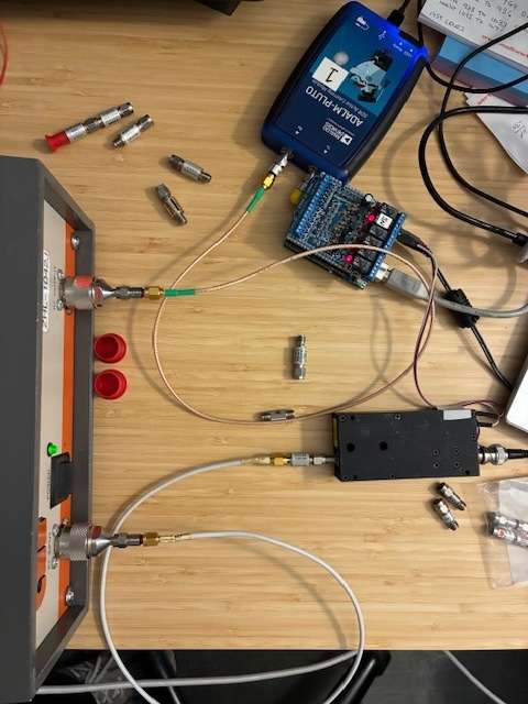
This existing system is detailed in three blog posts (post1, post2, post3) that walked through learning about the components and how to control them via the SATSAGEN software package. This page shares how to replace the commercial noise source with an inexpensive noise source put together from a few on-hand lab items. A future web page or blog post will show how I will replace the moderately expensive Pluto SDR with an inexpensive RTL-SDR USB receiver stick. This lower cost system will support noise figure measurements within the RTL-SDR's 30 to 1,400 MHz reception range.
How much noise is needed? The easy answer is that this varies a little depending upon the specific test sequence and item(s) tested. The HP346B noise source offers a starting point with an ENR of around 15 dB of noise from the source. If your source has a higher ENR, then it's OK to add a RF pad to the output to lower the ENR to be closer to ~ 15 dB. If the ENR is much lower than that, you may have trouble making noise figure measurements for some types of components. (For reference, the HP346A noise source has a lower ENR of about 5 dB over its operating range. This ENR level might be helpful for some measurement situations.)
The ultimate end goal of this project is to have an easily reproducible low-cost noise figure system based on a DIY noise source, an Arduino controlled relay (supporting hands-off NF measurements), and use an inexpensive a RTL-SDR receiver, all controlled by SATSAGEN software on a Windows PC. We'll begin this journey at the noise source end of the system.
Parts Needed
Listed below are the items I used to create a calibrated DIY noise source:
- TinySA-Ultra RF spectrum analyzer (or equivalent)
- +12VDC power supply (or power supply for the RF amplifier you've chosen)
- 2 or 3 RF attenuators (I used 5 dB attenuators in three places for my setup).
- One SMA to SMA adapter (used to attach the TinySA to the noise source)
- Noise Source, uncalibrated (aka, a common RF amplifier covering the RF frequencies I was interested in, in this case 50-440 MHz)
- An optional RF 50 Ohm termination (load) for use on the RF amplifier input
Measurement Method
The SATSAGEN noise figure measurement setup requires a noise source with a known Excess Noise Ratio (ENR), commonly expressed in dB above the KTB noise floor. Measuring ENR of an unknown source might be considered hard to do without specialized equipment, but the TinySA-Ultra saves the day and makes this quite easy.
I used a surplus (~$20 used) COTS RF amplifier module (Mini-Circuits ZFL-500) as my noise source and employed a trick on the TinySA noise figure software routine to directly measure the ENR of the RF amplifier (essentially allowing turning it into a noise source). NF was measured, but ENR was the output parameter. Virtually any RF amplifier will work as a noise source, and following this process, you can measure the ENR value needed to enter into your NF measurement system (SATSAGEN controlled, or other). Let's calibrate the noise source and find its ENR values for 28 MHz through 440 MHz.
First, we should work to minimize measurement error by adding a some attenuators to stabilize the impedance of our system. The output impedance of an RF amplifier may shift when being switched from OFF to ON states and or even with the input connected to a termination or just left open. Having a surplus of 5 dB SMA RF attenuators, I added one to the RF amplifier's input jack and added two together to add to the amp's output jack. (If you have an extra 50 Ohm termination, you can use that on the input connection instead of the 5 dB pad.) Adding these yields 10 dB return loss on the input side and a minimum of 20 dB return loss at the output. The output 10 dB pad reduces the ENR noise level, but still leaves plenty of excess noise to work with. Adding the output pad reduces the impedance shift from off to on and on to off, and is close-enough to isolating any ON/OFF changes from disturbing the ENR measurement process. (I added additional 5 dB pads on the input and output side and saw no change in my measured ENR values.)
With these in place, get started by adding a loop back calibration cable on your TinySA (CAL to RF jacks) and run the calibration routine for your analyzer.
Next, attach the powered-off RF amplifier (noise source) output jack (amp out) to your TinySA RF input using any needed adapters (BNC, SMA, etc.). I used a SMA-Male to SMA-Male RF adapter for my setup.
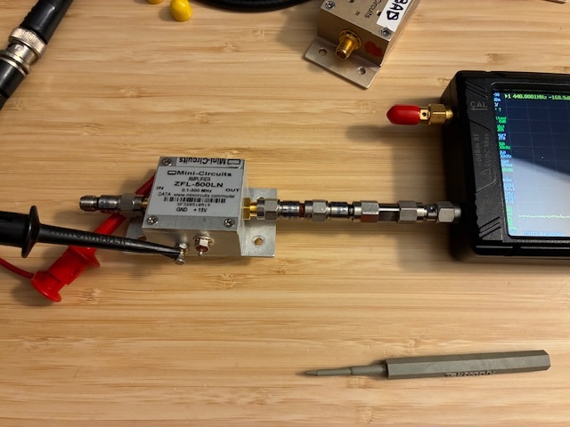
The photo above shows the input side 5 dB SMA pad connected to the RF amplifier's input jack, two 5 dB pads connected to the output jack, a SMA-M to SMA-M adapter, connected to a SMA connector saver (SMA-F to SMA-M) attached to the RF port of the TinySA RF spectrum analyzer. The red ez-hook with DC power is disconnected from the amplifier's +DC input pin (the amplifier is OFF).
Accessing the TinySA menu functions (MEASURE, MORE, NOISE FIGURE), you'll see four check boxes to complete.
- First measures the base level noise of the TinySA. Wait about 30 seconds after selecting this.
- Then select the second box.
- This finishes quickly and automatically starts a third verification phase where the noise level is measured and compared against the first measurement. Wait about 45-60 seconds after selecting the third step - such that the error reported at the top right of the screen reads zero (0).
- Then select the last step (MEASURE AMP NF) followed by these two steps: 1) turn on the DC power supply to your RF amplifier/noise-source, wait a few seconds for it to power up and stabilize, and 2) respond to the EXT GAIN (Amplifier Gain) question on the pop-up window by selecting zero (0) followed by enter (x1) lower right button.
If you were measuring Noise Figure of an amplifier, you would have entered the previously measured RF gain value (measured with your NanoVNA or other instrument), but here, we're just looking for the difference between the KTB noise floor and the output noise level of your noise source (RF Amp). Selecting zero for the Amplifier Gain makes this easy to yield ENR of the noise source instead of the NF of an amplifier.
We've now completed the ENR measurement of our noise source for one frequency. Repeat the process (power down source, select frequency, measure TinySA noise floor, validate TinySA noise floor, power up noise source, measure ENR) for each frequency needed. Once you have an ENR table for your source, you can enter it into your NF measurement system (SATSAGEN controlled or other).
Here is my table for my DIY Noise Source ENR values based on the Mini-Circuits ZFL-500LN RF amplifier. Also measured the ENR values for the COTS source (with a 20 dB pad attached).
| Frequency (MHz) | DIY Noise Src ENR (dB) | NC3404T ENR (dB) [-20] |
| 28 | 20.5 | 5.1 |
| 52 | 20.5 | 8.5 |
| 146 | 21.0 | 13.9 |
| 440 | 20.1 | 14.8 |
| 902 | 17.0 | 14.7 |
| 1296 | 16.1 | 15.1 |
| 2400 | 8.4 | 13.0 |
| 3000 | - | 12.2 |
| 4000 | - | 20.6 (suspect) |
You can see that using a +12VDC supply to power the DIY Noise Source (ZFL-500 RF amplifier), that we are a little above our 15 dB ENR target and that the ENR starts to roll off above 500 MHz. Without the two 5 dB pads on the output, we would be even higher (closer to 30 dB ENR). Adding the 10 dB of attenuation has dual benefits: Reducing on/off impedance shifts and lowering the source ENR to be closer to the 15 dB ENR target. (The Noise Com source has ENR of over 30 dB in the 2-4 GHz range per the attached label. I have used this successfully with a 20 dB pad on the output port.)
The TinySA-Ultra seems to have difficulty in measuring ENR above 4 GHz'ish, likely due to a rising noise floor within the analyzer's front-end. Will look at this a little closer in the future.
With ENR values entered into the SATSAGEN software, the new DIY noise source can be used to measure noise figure for the listed frequency bands. Note that these values cover broad frequency ranges and can be used for the entire frequency band, not just the specific frequency listed.
The remaining step is to create a voltage supply interface that will allow SATSAGEN to automatically turn on and off the new DIY noise source under program control. This will require some minor rewiring of the existing Arduino UNO relay board wiring and will be included below when completed.
As background, the existing COTS Noise Com source needed to have a control pin grounded to turn off the noise, so a relay was used to ground this pin under UNO/program control. The new DIY noise source needs to have its +12 VDC supply voltage fed to the amp to turn the noise on and the supply removed to turn the noise off.
With a few changes to the relay interface, the two noise sources (DIY ham-bands ZFL-500 RF Amp and the COTS Noise Com NC3404T) will be ready for general lab use.
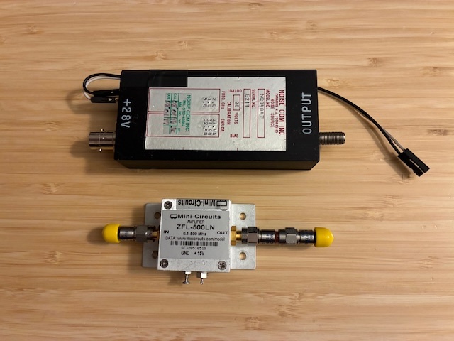
Photo above showing Noise Com NC3404T (top) and Mini-Circuits ZFL-500LN (bottom).
More fun ahead (now with more noise)!
Information for other DIY test equipment is listed on this page: https://qsl.net/n8dmt/test-page/diy-test-equipment/index.html
Author photos taken with an iPhone-16e.