AN-SOF MPAS-Lite Vertical with Lazy Sloper
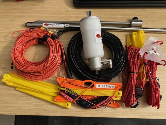
This is an AN-SOF antenna model for a Chameleon Antenna MPAS-Lite ground mounted vertical antenna with added DIY 60' Lazy Sloper Wire using the CHA 5:1 Hybrid Mini, CHA SS-17 telescoping 17' whip, ground mounted spike, 4 each DIY 25' counterpoise wires, and 50' of RG-58C coaxial feed line. This model assumes average North American ground properties.
Per the Chameleon Antenna website, the 60' Lazy Sloper Wire is said to enhance signal radiation and reception, provide broadbanding effects, improve efficiency, and provide directional properties beyond the omni-directional MPAS-Lite vertical antenna system.
Readers of this blog are encouraged to compare the VSWR/return-loss and far-field pattern characteristics of this "vertical + sloper" antenna against the baseline MPAS-Lite Vertical antenna system previously modeled.
This analysis does not call out many of the analysis/setup steps and instead, focuses on the key analysis results needed to understand the top-level performance of the antenna. See the 10m vertical in free space post for a walk through with all the detailed steps called out.
Analysis Parameters:
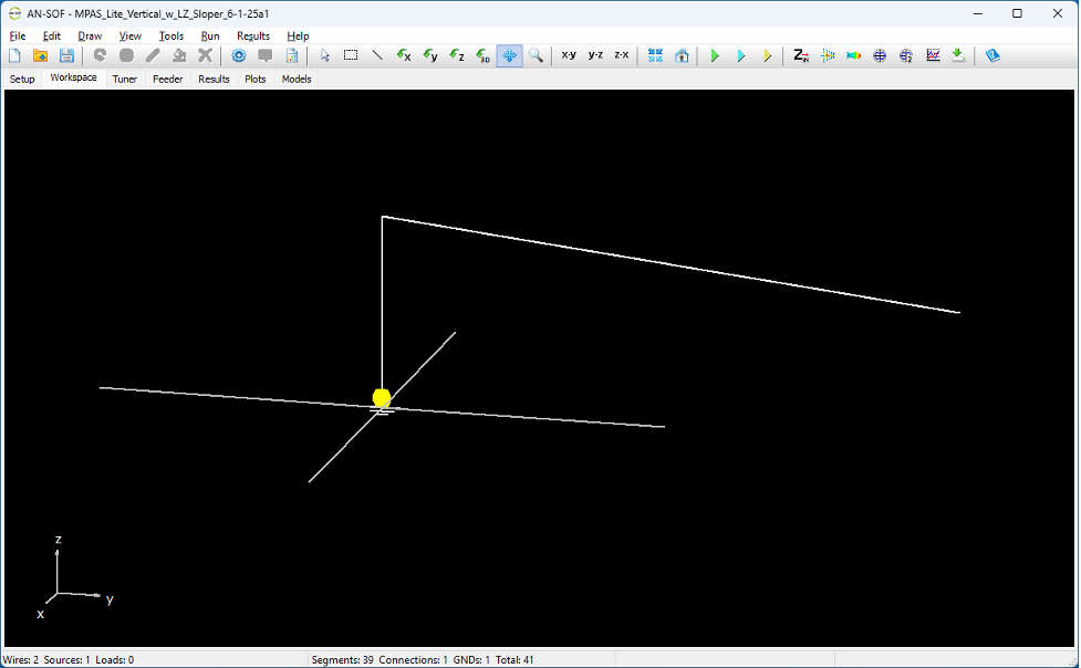
- 5.182m (17’) vertical with 1:5 unun, 4 ea 25’ counterpoise, 60’ LZ Sloper from 5.182m down to 0.1m (ground)
- The far end of the sloper wire is insulated / not-grounded.
- Sloper wire ends in X, Y, Z (19 segments, 1mm radius, 18.2401m, 59.84 feet)
0, 0, 5.182
-12.387, 12.387, 0.1
Setup simulation and counterpoise parameters:

For orientation of the sloper wire, chose to have it between two of the counterpoise wires rather than over the top of one of the radials.
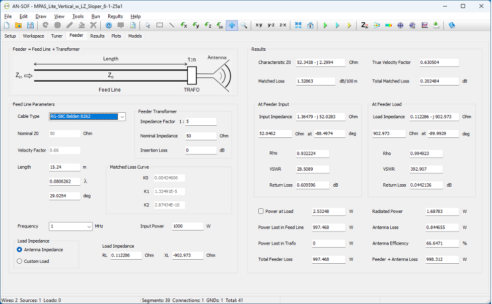
Same feeder parameters as the MPAS-Lite Vertical.
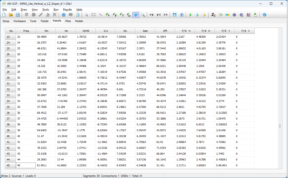
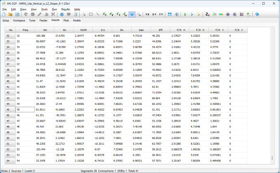
Running the simulation, the following tabular results are available (next three screen captures).
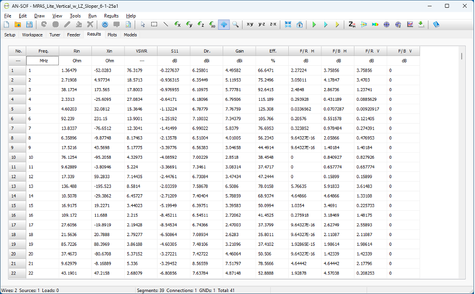
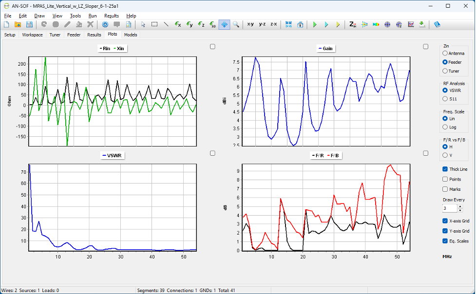
The results plots show reduced VSWR over the lower frequencies than the vertical without sloper configuration.

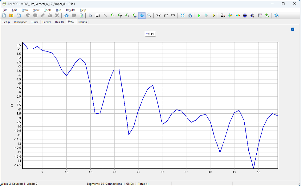
Here's S11(dB) for those that prefer S11 over VSWR charts.
The next series of screen shots are for the far-field antenna patterns. Tried to include these for the HF ham bands where this antenna is likely to be used.
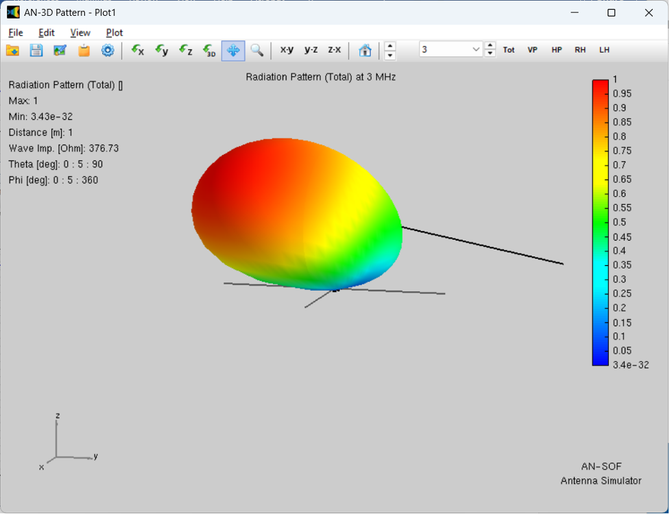
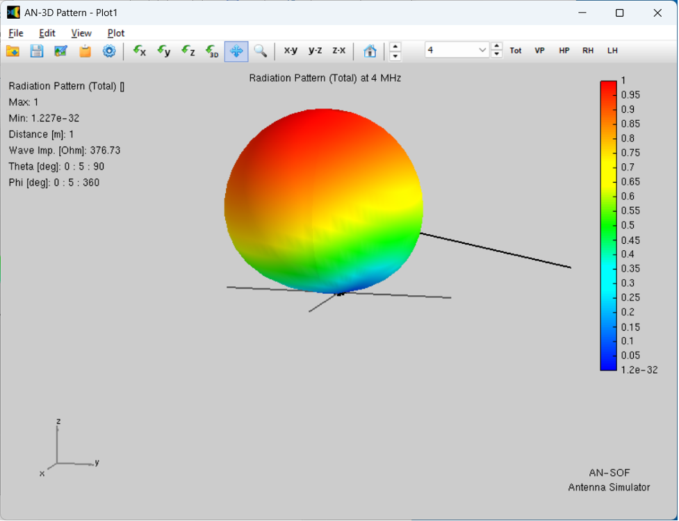
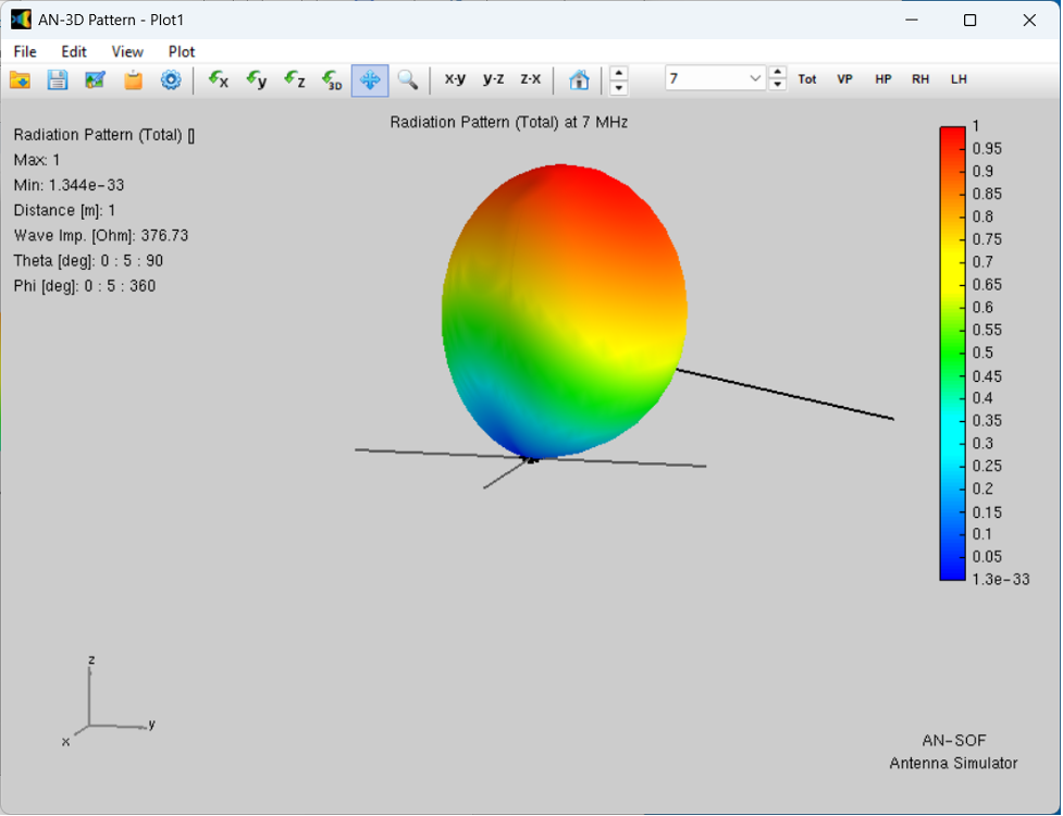
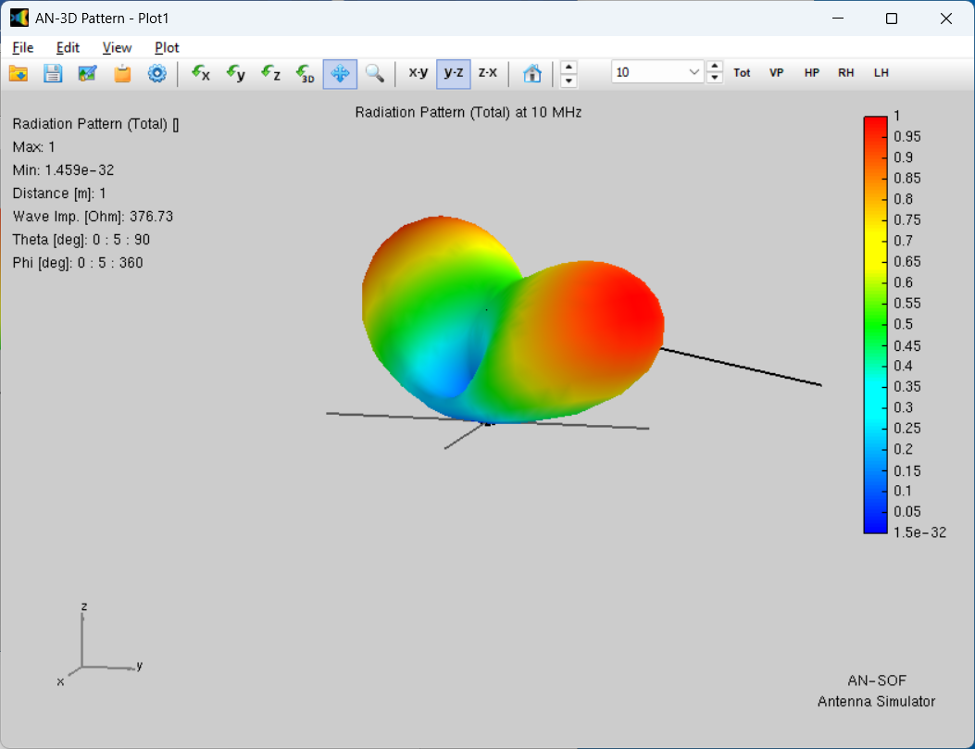
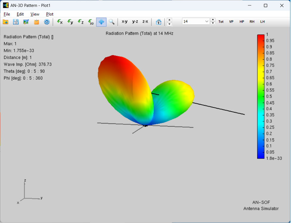

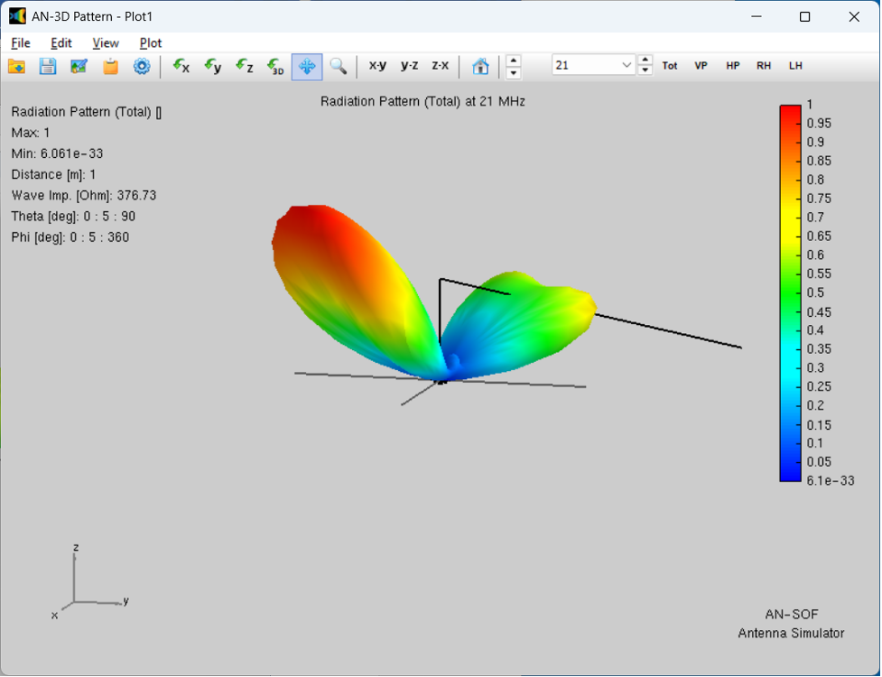
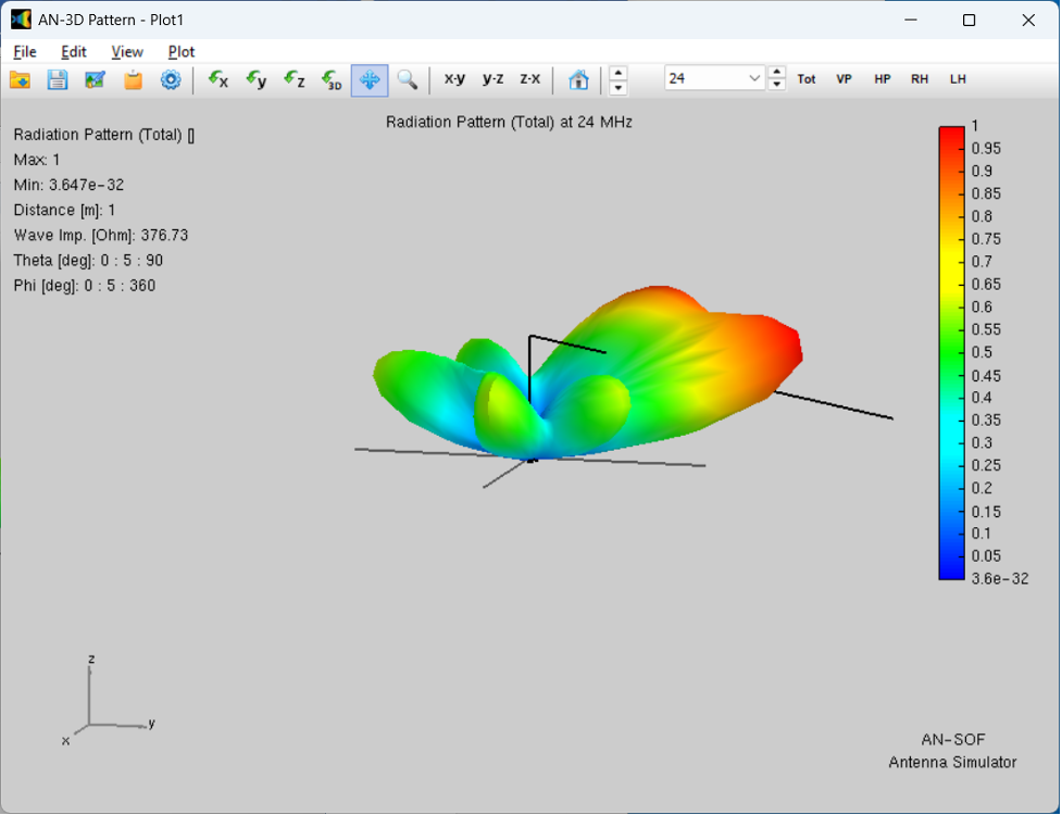
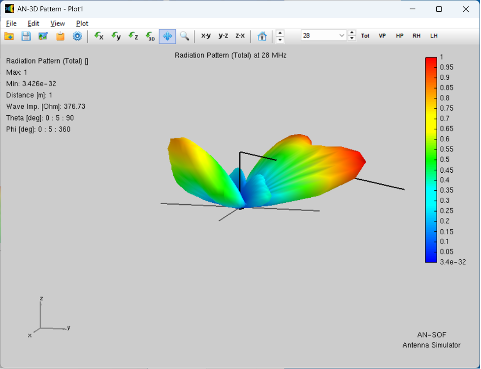
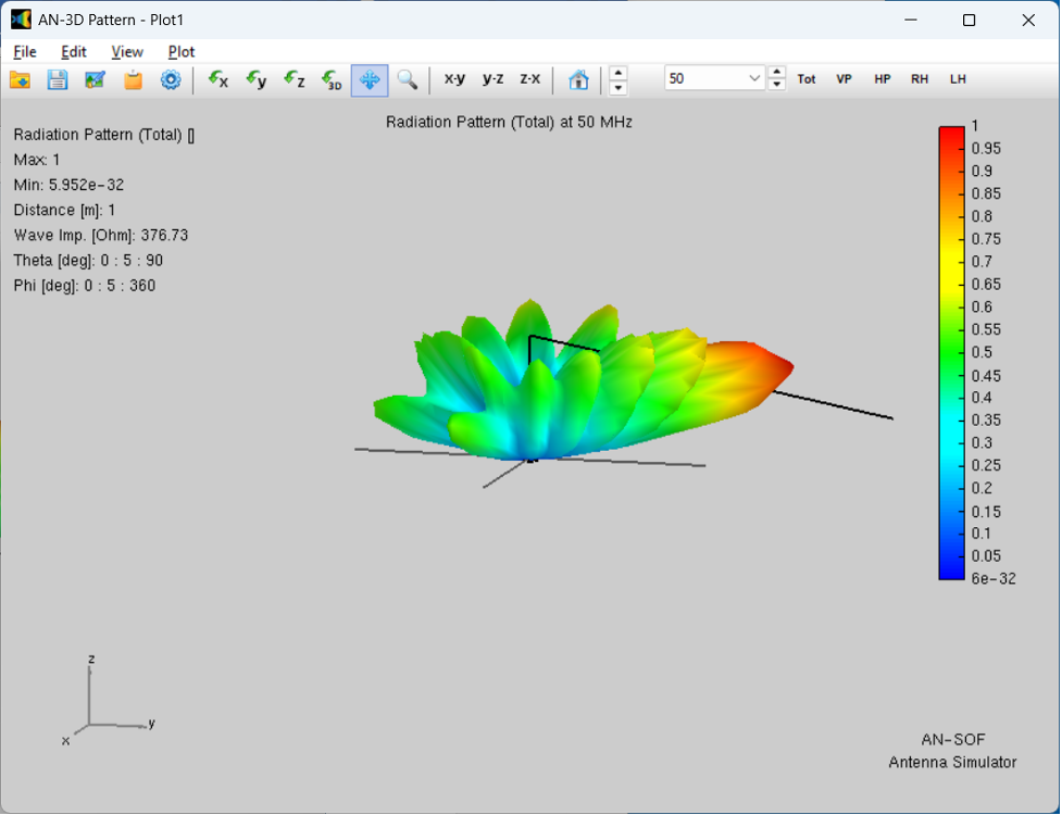
Conclusions: The addition of the Lazy Sloper wire appears to improve low frequency performance with gain / directivity compared to the omni-directional MPAS-Lite Vertical configuration. VSWR is improved and likely efficiency too due to the larger aperture size with the LZ wire added. Above 7 MHz (40 meters) there is likely less directivity and certainly more pattern moding as the frequency is increased.
Using this 60' sloper wire is an option for addition to the baseline MPAS-Lite Vertical antenna planned for use in the 2025 ARRL Field Day event. Thought would be to add it to the top of the vertical antenna for the Saturday evening/overnight period, but not have it attached when the sun is up and higher frequencies likely used.
Depending upon the antenna base location for this year's activity, the LZ sloper wire may best be placed/routed in the direction of the building in order to point the (opposite) 80m band maximum gain lobe/pattern in the Southern direction. This will be a challenge as the antenna is only about 45' away from the structure on the South side. Will give this more thought as Field Day planning continues...
Want to try simulating your antenna designs? Try AN-SOF from https://antennasimulator.com/ and begin your learning journey into the fascinating world of antenna analysis and design.
Here is the main page for my AN-SOF antenna simulations.