Installing a AT-D578UV Mobile
As part of 2025's DMR VHF/UHF radio upgrade for the family, I purchased an AnyTone AT-D578 UV mobile along with two AT-D878UV portables and successfully programmed all for simplex & repeaters here in EN52 Chicagoland. While the portables were seeing regular use (including in the car), the mobile was only being used inside the house powered by the ham station's 12V DC supply and attached to a temporary inside (HOA limited) multi-band antenna. After purchase of the new radios, the job scope to install the mobile into the car was examined but appeared to have a few power-connection challenges that just looked like too much effort for that moment.
Fast forward almost 12 months and with a few dozen internet videos explored, it was time to reexamine putting the mobile into the car. The UHF mount Diamond HRKS antenna mount was fastened to the rear hatch glass, a Comet B-10 UHF-mount whip antenna attached, and the mount's coax routed inside to where the mobile was thought to end up. Two things were discovered facilitating simplified installation of the AT-D578 mobile:
1. Review of the vehicle's 12V power layout and routing showed that there was a fuse panel literally six inches directly below the planned radio mounting location.
2. One of the internet video radio installers had used a gizmo called a "fuse tap" to easily wire into an existing fuse panel fuse location to obtain power for the radio. Their car make/model was the same as mine and I hoped to be able to use this same approach to obtain 12V switched-with-ignition power. Would fuse location #25 work for me?
And so the quest to get the mobile installed began...
I started with a review of the radio's power cord and fuse values. This would give some idea of how much power the radio needed from the vehicle source.
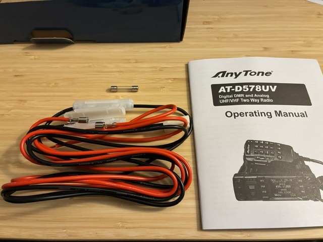
The radio's supplied power cord had two 15A 250V fast blow fuses, one in the positive lead and one in the negative. The AnyTone used a T-style power connection about 12 inches from the radio body. There was another in-line fuse on the positive power lead between the radio and the T-connector.

I had purchased an additional (aftermarket) cable with the mobile that converted the T-connector to Power Pole (PP) connections. This was used inside the house to hook up to the station's 12V supply. The adapter came with fuses in both the positive and negative leads.

My original thought was to use the power pole adapter cable in the car allowing other uses of the mobile's DC power source via the PP jack set I would install.
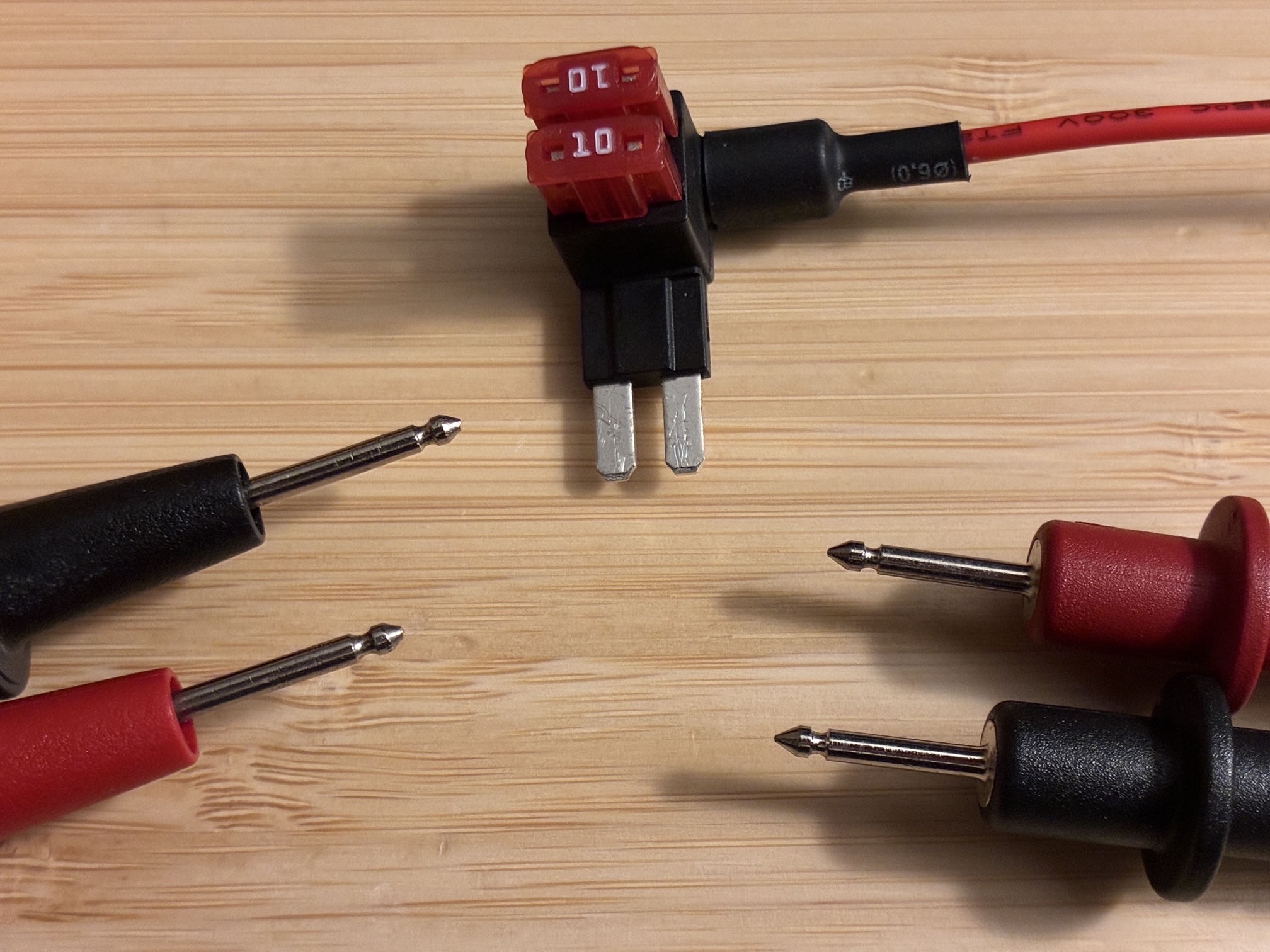
A trip to the local automotive parts store yielded the magic fuse-tap adapter and a set of 10A Micro blade fuses needed to limit draw at the tap point to the vehicle's accessory power rating of 10A (per vehicle specifications).
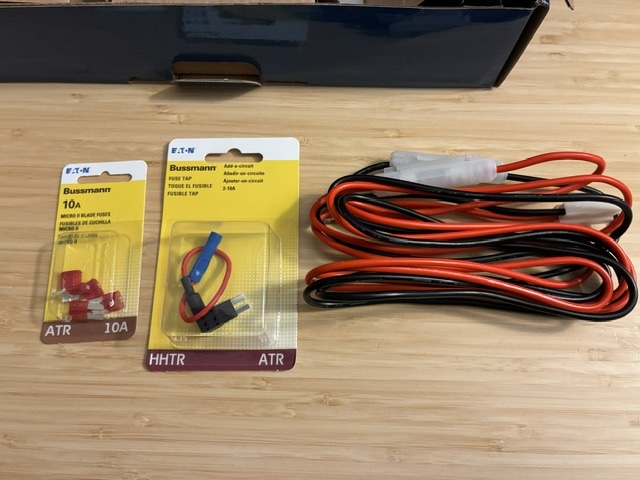
More on the Bussmann (Eaton) HHTR - ATR fuse tap. The specifics of the wire used are apparently not available online, so sharing wire marking details here:
Style 3266 125 Deg C 300V 16 AWG 3A AWM 1A
Package is marked 2-10A and includes note to reverse tap direction in socket if initial insertion does not provide power to added accessory (with original circuit fuse not installed).
Comment: #16 wire is not optimal, but should work if kept short (< 6”).

The adapter came with a pre-crimped but-splice crimp sleeve to attach to your device power lead. Note that this is blue (#14-16) and not yellow (#10-12) wire size. I hoped to be able to carefully squeeze my available red #12 wire into that crimp connection...
With the car's 10A limit on the #25 fuse connection, I thought it might be a good idea to measure the radio's DC power draw to see if I would need to limit use of the Turbo power level (highest setting) on the radio. I also checked the radio's programmed channel list to ensure that all channels used High, Medium, or Low TX power settings (none were set to Turbo).
The radio was connected to a dummy load for these DC power draw tests.
My PowerWerx SPS-30DM station supply has a built in current draw indicator. I figured this was close enough to see if I was even getting close to the 10A source limit of the car. The power draw vs power level chart is below. Conclusion was that there should be no concern if operated at High power or below. Good to proceed...

It was time to explore finding power at the fuse panel just below where the radio would mount. This turned out to be the most frustrating part of the entire job.
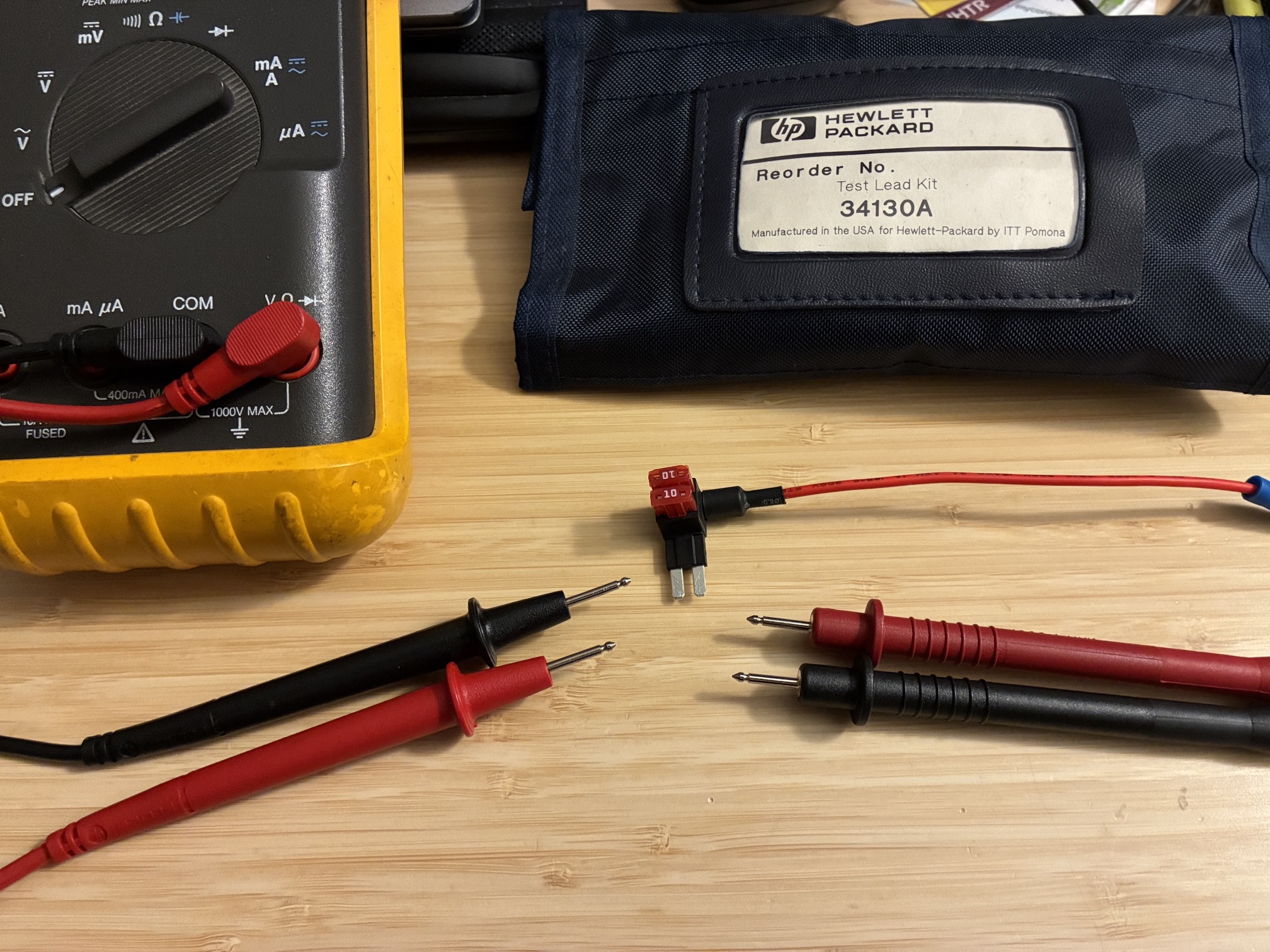
The fuse tap cable and Fluke 87 DVM were brought out to the car, the vehicle pulled out onto the driveway (allowing engine on/off testing) and multiple points on the fuse panel examined for the presence of +12V DC.
This was pretty much a 100% fail, with no measured fuse-top test points showing 12V power with either engine on or off. (!!!)
So, what's happening?
In the above photo you can see the test leads provided with the Fluke 87 meter. Taking the meter out to the car again, I tried to test for the presence of +12V DC (car on or car off) across multiple points on the many fuses installed in the panel. I even inserted the fuse-tap into fuse #25 location (trying insertion both ways) with no success. I could find 12V on the major bus wire post feeding the panel, but not on any of the fuse test points for all fuses in the panel. See below for a close up of the Micro fuses and how they have small test points at each end at the top of the fuse body.
You'll notice that there was a test lead set at the right of the second photo above (HP34130). These are the probes zoomed-in pictured on the right side of the above photo. See how they have more of a pointed end than the blunt end of the Fluke test leads at left?
This small difference was enough to make continuity into the fuse test points using the HP leads, and resulted in being able to measure voltages at various points in the panel. Sure enough, fuse location #25 provided 12V power when the engine was in on (run) position. It turns off the radio when the engine is turned off - exactly as desired so as to not ever run down the battery in the car by drawing power to the radio when the car is off.
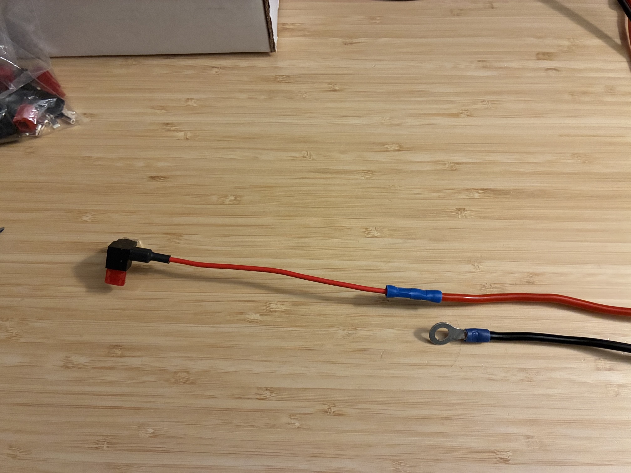
With that, it was time to wire up the power feed from the tap set to a short length of #12 red/black wires and terminate in a set of power poles at the base of the radio mounting location. The #12 positive lead snugly fit into the blue but-splice connector without losing any strands. Did not achieve full compression on the crimp joint, but it is FIRMLY crimped onto the wire and passed a firm pull test. A chassis ground bolt was found nearby to support the radio return lead. This had a ring terminal attached to the black wire.
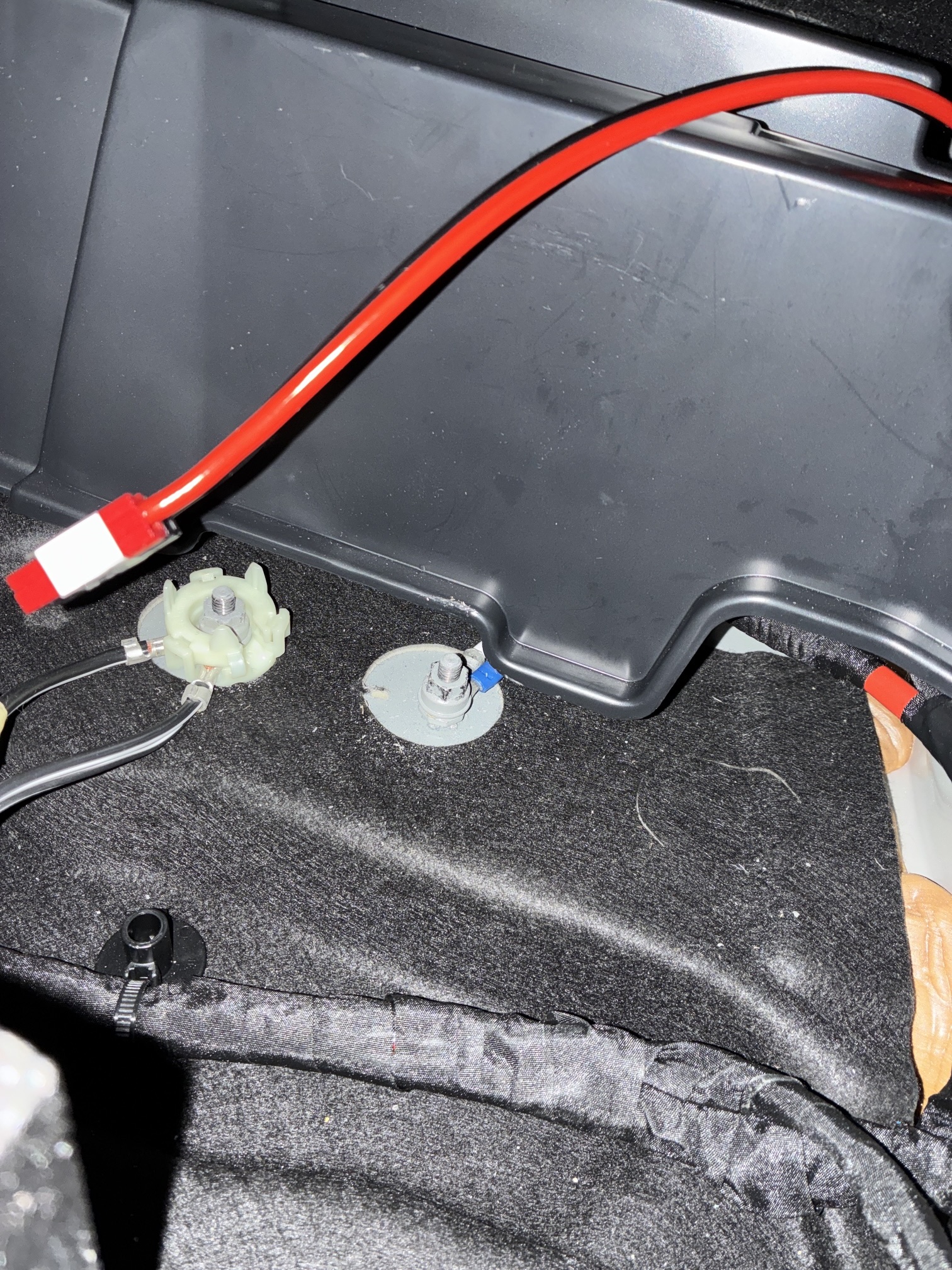
The photo below shows the negative lead (blue ring lug) grounded under the chassis bolt in the center of the image. Had to dig out the metric socket set to install the ground connection under the nut.
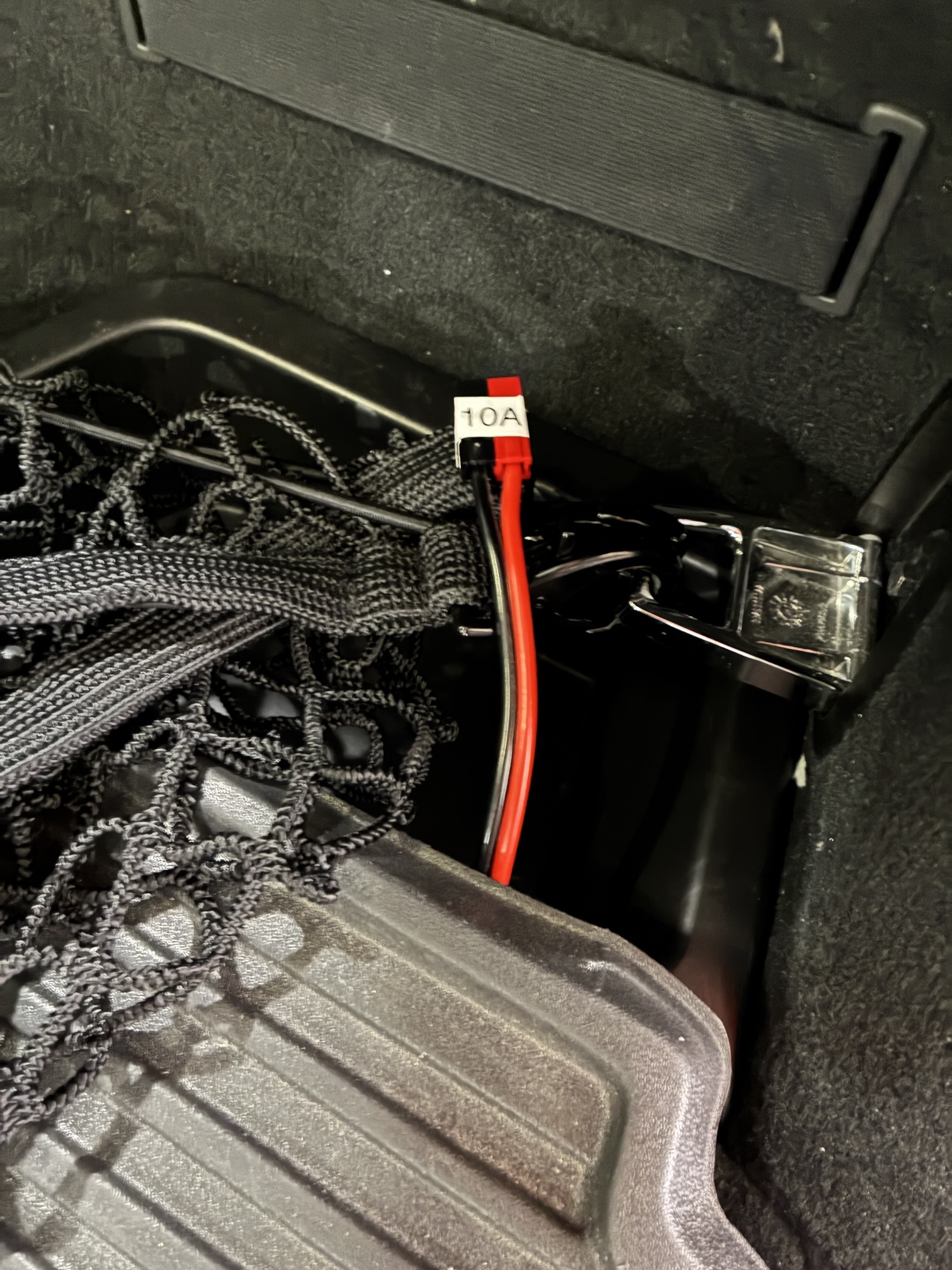
The image below shows the inserted fuse tap at fuse #25 location with the wire snaked around and exiting the fuse panel at the lower right side.
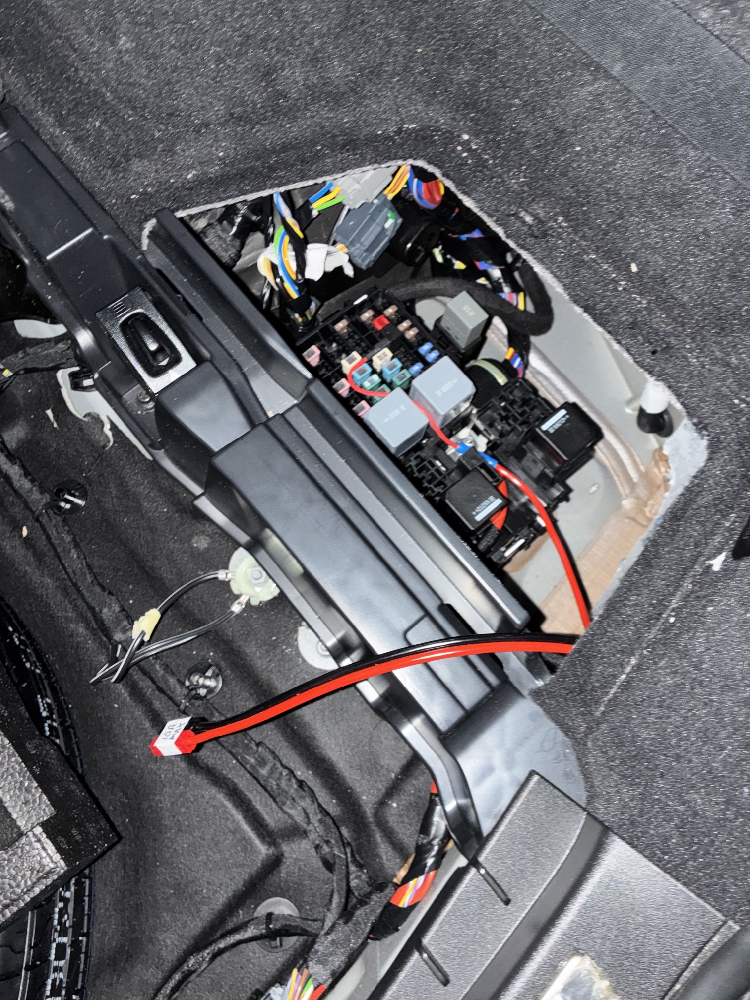
With the leads safely routed and the fuse panel cover in place, the remainder of the car was put back together leaving a relatively short power pole cable available at the radio mounting location. I added a 10A Max cable label at the PP connector set as a reminder that this cable should not be used for the 100W HF mobile (unless RF power is turned way back before connection/use).
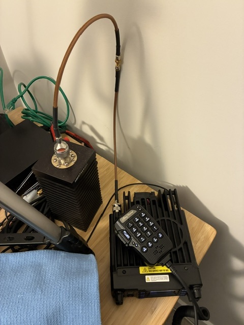
With power and antenna available, it was time to actually install the AT-D578UV mobile into the final mounting location at the rear of the car.
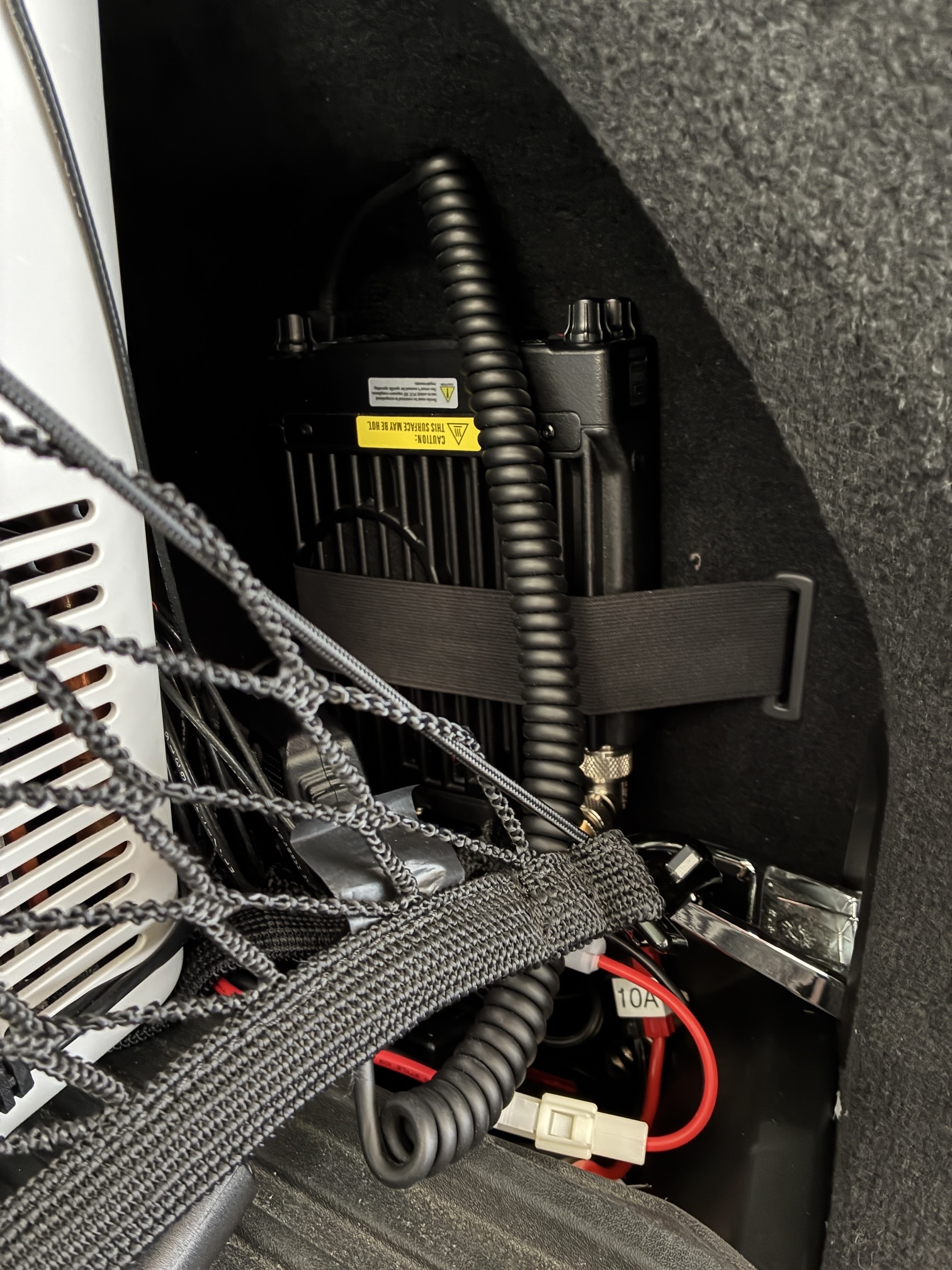
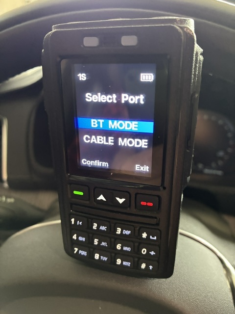
This is a good time to share that the AnyTone AT-D578UV mobile does not have a removable control head (and indeed you can see the coiled microphone cord and control knobs in the above picture). The plan was to remote mount the radio with short DC power and antenna coax lengths and then use the AnyTone BT-01 bluetooth remote microphone/control for the user (operator) interface functions up front in the car. (The BT-01 has a nice display, multiple control buttons including PTT, and good audio levels on both RX and TX.)
Below is a car-off picture showing the BT-01 unit starting up and looking for the radio. It is sized slightly smaller than the AnyTone AT-D878UV radio and is a-bit larger than a normal wired speaker microphone.
At this point, the mobile was in the car, hooked up, and capable of being used for DMR and FM QSO's on 144, 220, and 450 MHz. There was just one rub - the radio was asking for a confirmation of the date/time every time it was powered up. This was solved by attaching the provided GPS antenna to the mobile and placing it on a window ledge in the rear of the car. Once GPS lock was achieved, the confirm date/time message went away. (Imagine that!)

The last step to place the mobile into regular service was to print out a cheat sheet for the BT-01 accessory buttons (defining both short and long press functions) and then test the mobile for a week while driving around in my local area. I continued to carry and listen with one of the AnyTone AD-D878UV radios while in the car with the mobile on. As expected, a mobile with a good outside antenna works MUCH BETTER than a walkie talkie with the radio's stock whip inside the car.
Achievement Unlocked: Install an Amateur Radio VHF/UHF radio into the family vehicle replacing the need to use an HT inside the car. The new radio system works great!
All author captured photos taken with an iPhone 16e.