
Introduction to this Project
The UK's General Post Office (GPO) offered many different designs of telephones over the decades, slowly improving and adapting the design to suit the demands of the time. There has been an increasing interest in the older style telephones in recent years, with many people buying them purely as a display item.
This type of telephone uses pulse dialling, long since phased out in favour of tone dialling, and indeed with the advent of VoIP (Voice over Internet Protocol), this type of phone will now be unusable on most public networks unless some kind of interface is used.
One way to make use of these iconic and collectable devices in the modern world is to create a two-telephone intercom system, and this page's function is primarily to document how I got such a system working, including the ability to ring the distant phone. Setting up a pair of phones in this manner is in essence pretty simple, but there are things that need to be attended to.
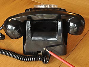
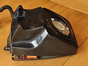
The telephone of particular interest to me for this project is the GPO's type 746 rotary automatic telephone, as I consider this represents the peak of development before things started to become too 'electronic', and it has the benefit of a real bell.

Example of details printed on the underside of the telephone
The details of the telephone should be found printed on the underside as in the image above. The first number indicates the model number and the 'F' suffix indicates, I believe, that the dial has just numbers, rather than numbers and letters; the SPK bit indicates the manufacturer, in this case Speke Telephones, and the last bit gives the year and production run.
Using electronics it is entirely feasible to create a local exchange for linking many of these phones together and there are several resources on the web detailing how to do it, and ready-made units are available to purchase, should you wish to do this instead of making an intercom.
Getting Inside a Type 746 Telephone
Any such phone will arrive in an unknown configuration depending how and where it was last used, and it will need to be opened up to enable it to have the minor modifications done to make it suitable for intercom use.
First loosen the single screw at the rear of the unit which should stay attached to the plastic case; it should have a spring and a captive nut fitted in which case it would be unnecessary to completely remove the screw, but if an inexperienced person has been inside before, the nut may have been lost in which case the screw comes right out.
Loosen this screw |
Lifting off the cover |
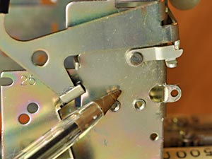
With the rear screw loosened, the rear of the case can be lifted slightly; as you do so, press the two cradle tabs down so they pop in under the case. As you continue to lift, take care to ensure the cover passes over the dial mechanism; it can be a tight fit, so be careful not to break anything.
If you have trouble easing the cover up over the dial assembly, you could remove the dial's clear plastic finger plate, which provides more room. This is done by first removing the small central clear plastic cover if present; this can be done without damaging it by sticking a bit of adhesive tape on it, and using that to pull it out, and removing any printed paper disc under it. This exposes the central screw which retains the finger plate.
The whole case can then be moved forwards to allow the front tab to disengage, allowing its removal. With the cover removed, the innards are revealed as pictured below.
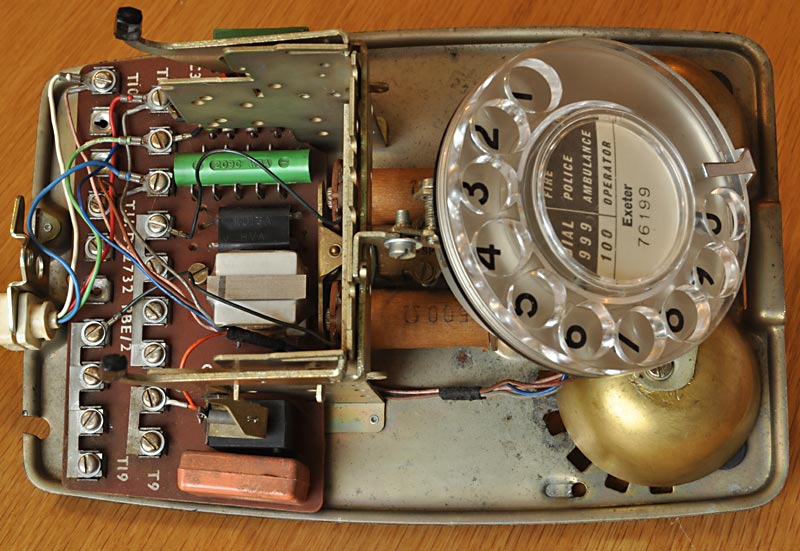
A type 746 telephone with the cover removed
These units were intended to last and were well-designed, attention given to ease of servicing and repair. You can just see the two light-brown bell coils in the centre of the chassis which have '500Ω' printed on them; this is the type of bell we need to have fitted, rather than the 'high impedance' type which has '2000Ω' marked on the coils.
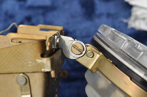
One useful design feature is the small latch that can be used to lock the cradle switch down, as with the cover off, the weight of the handset can no longer reliably do this. This is useful if work or tests need to be done on the unit with power still connected.
The latch loose |
The latch lifted & engaged |
The latch is generally located on the left side of the cradle support, as viewed from the front; to use it, press the cradle levers down, then lift the latch forwards and up so that its tab engages with the cradle bar. Releasing pressure on the cradle will retain the latch, until the cradle is pressed down which will allow the latch to swing out of the way, allowing the cradle to rise.
Dismantling the phone further for repair or deep cleaning may be required, in which case please refer to the dismantling, servicing & reassembly section further down the page for details on how to do this.
Technical Stuff for Reference
Although information on these telephones is widely available on the Internet thanks to a selection of excellent websites, I've included some technical information here for convenience and reference.
Type 746 Telephone Circuit Diagram
Below is my drawing of the circuitry inside a typical 746 telephone, based on official documentation, a copy of which can be found here: circuit description. The switch positions are shown in the rest condition, and the thick black conductors are the linking straps fitted between the screw terminals within the phone. The various flying leads connected to terminals within the telephone are shown in their usual colours.
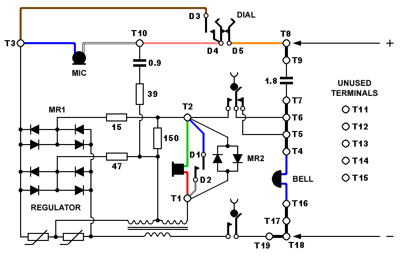
Type 746 telephone circuit diagram.
Although supply polarity is marked, phones will work either way round.
Dial & Bell Connections
The diagram below shows the connections to the dial assembly and the bell. All other connections and the straps have been omitted for clarity. The wires coming from the bell are shown blue here, but can be any colour and can be connected either way round.
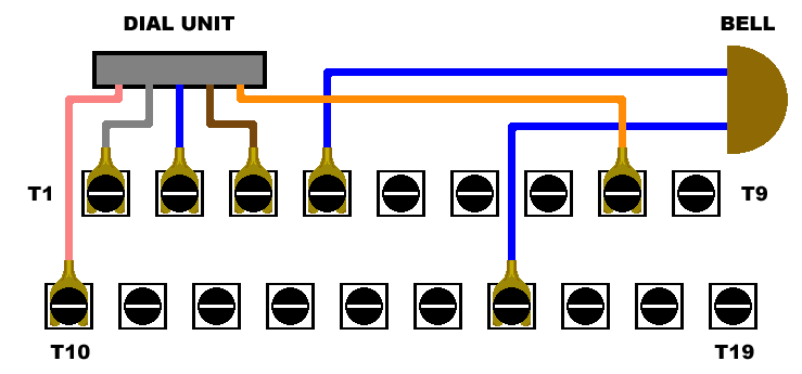
Showing the connections for the dial assembly and the bell
Handset Connections
The diagram below shows the connections for the handset; as before, for clarity no other connections and no straps have been shown.
The device labelled 'MR2' is a 'rectifier type 205' and consists of two selenium rectifiers connected in parallel but in opposite polarities, combined in a single package and connected across the earpiece. This acts as a sound level limiter by restricting the voltage across the earpiece to a maximum of about 0·5 - 0·7 volts, as anything above this causes the device to conduct, effectively clamping excess voltages to this level. This is to protect the user's hearing and possible damage to the earpiece, when voltage transients occur.
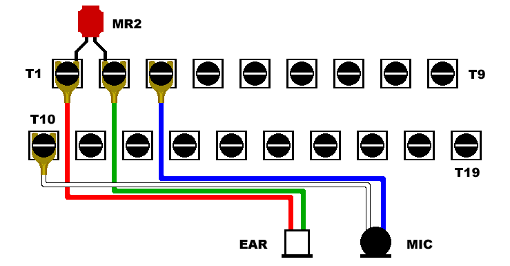
Showing the connections for handset and sound-limiter MR2
Original Line & Strap Configuration
For reference, the diagram below shows the way most telephones were configured when originally issued. Shown here are the incoming line connections and colours, and the locations of the straps. The layout of this type of telephone allows great flexibility in how it can be configured, so some may differ from this. Telephones which have been 'converted' will have an additional resistor fitted somewhere, and the straps and leads will have been rearranged.
Showing the line connections & strap locations as originally supplied
Converted Telephone Layout
These telephones no longer work on the public BT telephone network due to the change over to VoIP, but for reference the diagram below shows how the straps would have been arranged, the attachment points for the four incoming wires and the location of the 3,300 ohm resistor which limited the ring current for the bell, giving it the required REN (Ringer Equivalence Number) of 1.
The straps, incoming connections & resistor locations to convert a telephone.
Such a converted phone will also have a replacement lead terminated with the standard BT 431A plug.
About the Microphone
The 746 type telephones originally came with type 16 carbon granule microphones, which over the years can become noisy and unreliable. Some of these phones have had a replacement type 21A microphone fitted, usually as a result of a complaint about noise on the line, the noise actually originating from a faulty microphone.
These new type 21A microphones are generally of the electret type (although one supplier made dynamic units) which offered better sound quality and far superior reliability. Due to the nature of this type of microphone, some electronics were required which took the form of an integrated circuit fitted within the microphone casing.
Transmitter, type 16 |
Transmitter, type 21A |
The chip used in the type 21A electret unit is generally the Ferranti ZN470AE or ZN472E developed for telecommunications work and the resulting microphone was designed to be a direct drop-in replacement for the old carbon units.
It's reasonable to assume that the chip incorporated more features than just an amplifier; for example it included a bridge rectifier to ensure that polarity didn't matter, and as the unit had to be able to function with widely differing line currents, the chip must incorporate circuitry to deal with that, and protect the unit from voltage spikes.
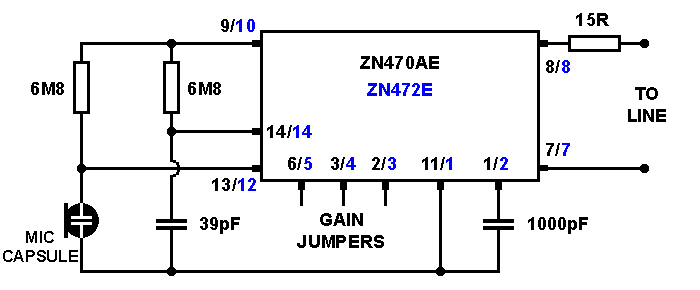
Circuitry within the type 21A microphone / transmitter unit
For interest's sake, I made some measurements on a particular unit using levels of line current between 5mA and 50mA, noting the voltage dropped across the microphone. From this I could calculate the power dissipation within the microphone unit, most of which would be generated within the chip; this data is displayed in the following table.
| Current | Voltage Dropped | Dissipation |
|---|---|---|
| 5mA | 4·93V | 25mW |
| 10mA | 5·17V | 52mW |
| 15mA | 5·39V | 81mW |
| 20mA | 5·77V | 112mW |
| 25mA | 6·47V | 161mW |
| 30mA | 6·97V | 209mW |
| 35mA | 7·15V | 250mW |
| 40mA | 7·32V | 293mW |
| 45mA | 7·53V | 339mW |
| 50mA | 7·69V | 385mW |
It's worth noting that the microphone worked equally well at currents as low as 2mA and at 50mA, demonstrating the effectiveness of the circuitry; obviously at higher line currents the chip has to dissipate more heat, and going by the ZN470 data sheet, its maximum rating seems to be around 100mA or so continuous, but this would cause the chip to run quite hot and may compromise long-term reliability.
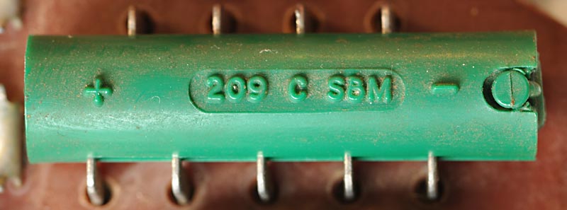
What's That Green Thingy?
The green cylindrical component on the circuit board (I've also seen blue and black ones) is a stack of 8 selenium diodes in series, with the 9 connections to them being visible on the sides. The associated pair of thermistors look like small light bulbs fitted into a black protective plastic mounting, and are located next to it.
The selenium diode stack MR1
The selenium diodes are in the form of eight small discs which are placed between nickel-plated contacts, the whole lot being clamped together by a surprisingly strong spring which bears against one end of the plastic cover.
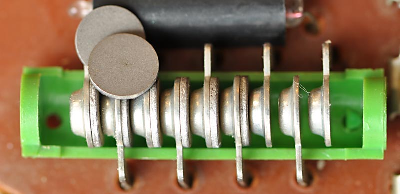
The selenium diode stack with the lid off, and individual discs
I made the mistake of frowning at one of these assemblies once, which upset it enough to make the green plastic case break under that spring pressure exposing its innards, and allowing the spring to ping forth into another dimension. So... that plastic has become brittle over the years, touch it if you dare! This did, however, give me a chance to photograph the construction of the diode stack.
The function of this diode stack is to act, in conjunction with the two thermistors, as a regulator for the audio, because if you were close to an exchange, the line current would be high causing the carbon microphones to have too high an output.
Quoted from a GPO student training paper 1969
During field trials of the 700 type telephone it was found that on short lines the telephone was too loud. An automatic regulator, Regulator No.1 is included to limit the sensitivity on short lines whilst allowing full efficiency on long lines.
The method of automatic regulation used is that of including a line-current sensitive regulator within the telephone. The regulator circuit can be seen consisting basically of a variable-loss network having a low D.C. resistance in series with the transmitter, with connections to the receiver circuit.
It provides shunt paths across the transmitter and receiver, such that, on short lines with full feeding current (say 95mA), the shunt impedance is low, thus more current will be shunted away from the transmitter and receiver, reducing their sensitivity. On long lines with currents 30-40mA, the shunt impedance rises to several kilo ohms, thus the shunt currents are very small, and the sensitivity of the transmitter and receiver is normal.
- Source: Bob's Telephone Files: Sensitivity Regulator
One of the beauties of selenium rectifiers is the way they slowly begin conducting as the forward voltage is increased, so although now considered old technology, they were ideal for this application.
In later times, exchanges limited the line current so that telephones close to an exchange didn't receive an unnecessarily high current; that and the fitting of electret microphones made the regulator within the telephone redundant, but it was retained for backwards compatibility.
At low line currents (say 30mA or less) there is insufficient voltage generated across the thermistors to bias the selenium diodes into conduction, therefore the regulator has no effect and doesn't need to be disabled in any way.
Making the Intercom
The object here is to make two telephones work as an intercom, and to be able to make the bell ring on the distant phone. As it happens, a pair of phones may well work this way with no modifications, but we need to check the configuration and there are things we can do to improve the way they work.
Surprisingly enough, two telephones are required; I've found the most suitable to be the type 746 (or the 741 wall-mounting version), which also seems to be the most common which is helpful.
Both phones should have the electret type 21A microphones fitted; if an old carbon microphone is present it may operate in an unpredictable manner, if it operates at all so is best replaced. Replacement electret units can be found for sale or in another donor phone and are fitted as a direct replacement.
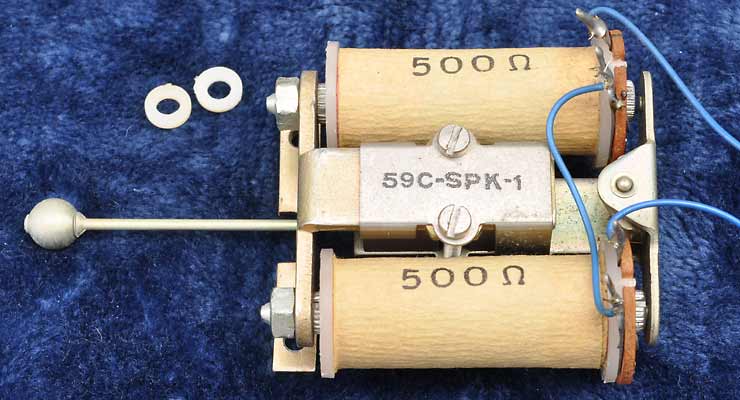
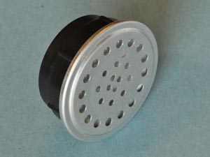
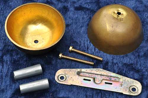
A No. 59C-1 bell unit and its two plastic spacer washers
For the ring function to work as predicted, both phones should have the older bell assembly fitted, which consists of two coils of 500 ohms resistance wired in series, with '500Ω' being printed on both coils to aid identification.
However, among the samples I have here, there seems to be a difference in sensitivity, related to a variation in clearance between the core faces and the residual studs on the armature. The units with larger clearances don't ring properly on the voltages used here, but adjustment is possible. See Bob's Telephone Files for information on how to do this.
The higher impedance bells with '2000Ω' printed on each coil sort-of work, but performance is marginal with the voltages suggested here.
There is quite a bit of information in this section explaining why certain modifications are to be made and how they were arrived at, so the main four steps have been numbered and high-lighted for quick reference.
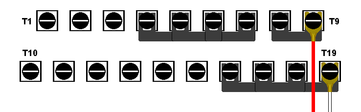
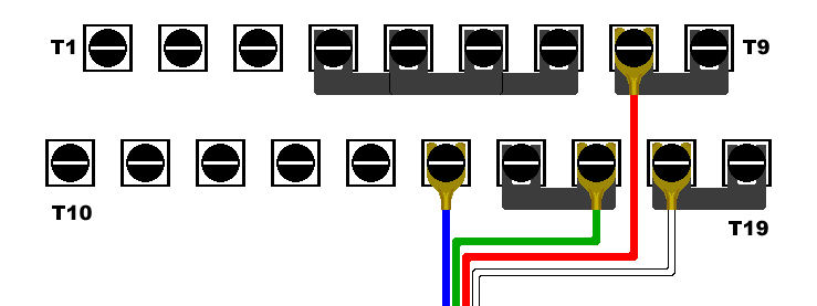
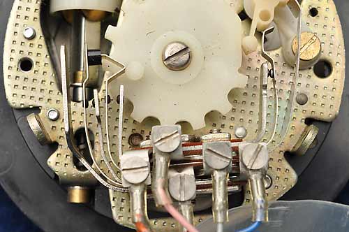
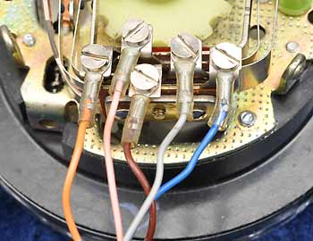
Showing where straps and wires should be fitted for intercom use
1. The telephones need to be modified slightly by altering the straps between the screw terminals, and any conversion resistor should be removed. The photo above shows where the straps should be placed. Ensure the handset, dial and bell connections are on the correct terminals according to the diagrams in the 'technical' section, with the exception of moving one bell wire from T16 to T18; this is simply to reduce the number of straps needed. Power is applied to T9 & T19.
Tests have shown that the microphones will operate well at less than 2mA, but this beautifully low current is insufficient to operate the bells when required, so we need to go for a higher current, and 20mA is plenty for reliable ringing with all the bell assemblies I have here that have the armature clearance set to 20 thousandths of an inch, and using a 40V supply.
With both phones in use and assuming good current-sharing between them, each phone will then draw around 10mA which is nicely low, keeping stress on the chip within those old microphones to a minimum.
2. A DC power supply needs to be constructed, capable of supplying around 40V open-circuit but it must be current-limited by a series resistance to around 20mA under short-circuit conditions. This supply should be well-smoothed and replaces the line current normally expected from the exchange.
A stabilised power supply having a voltage regulated at 40V and current limiting to around 20mA could be built, but this is a massive over-complication, is of no benefit and would probably necessitate the use of a choke; just use a resistor!
The table below shows suitable resistances at various voltages to give around 20mA of operating current. The telephone's circuitry normally drops between 5 & 6 volts when in use, so this has been allowed for in the calculations.
| Supply Voltage | Series Resistance | Operating Current | Shorted Current |
|---|---|---|---|
| 35 volts | 1500Ω | 19mA | 23mA |
| 40 volts | 1800Ω | 19mA | 22mA |
| 45 volts | 2200Ω | 18mA | 20mA |
| 50 volts | 2200Ω | 20mA | 23mA |
The speech signal produced by the microphone needs be isolated from the low impedance of the power supply, but the current limiting resistor alone provides good isolation. I experimented with a 1H choke in series with the supply which was enough to completely block any audio, but it made no noticeable difference to the speech level, confirming that the current limiting resistor alone is adequate.
3. This system only requires two wires to be connected: the positive wire should go to terminal T9, the negative to T19. Any spare wires can be fixed to any of the unused terminals (T11 to T17) to keep them from flapping around and causing trouble.
The telephones could be simply connected to each other using the two wires, and power fed to whichever telephone is convenient using those same connections; power will obviously pass to the other telephone as well, through the linking wires.
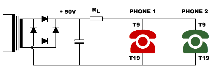
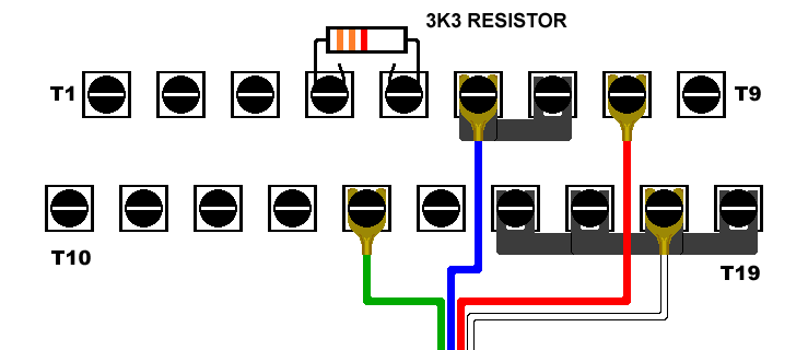
Diagram showing how power supply and phones are connected together
The two 220Ω resistors in the negative line and the 4·7µF capacitor are optional components; the resistors help with current sharing between the phones, and the capacitor bypasses those resistors as far as AC is concerned, increasing transmitted speech by a few dB. The resistors also have another use, should you wish to add a dialling tone as detailed in this section: Adding A Dialling Tone
At this stage, with the two telephones linked together and the power supply connected, a conversation can now be made when both handsets are lifted. To ring the distant phone, lift the handset and turn the dial to, say, '0', and let it go. As it returns, the bell in the distant phone might ring a bit if you are lucky, assuming its handset is on the cradle and the contacts in the dial unit are in good condition.
The reason for the dodgy bell ringing is that originally the bell circuit would be fed with a voltage of possibly 75 volts or more at a frequency of around 16 - 20Hz give or take, and under these conditions the bell's 1·8µF capacitor works well. However, at our lower working voltages and the lower 10Hz frequency of the dial pulses, the capacitor is a bit restrictive making the bell sound a bit pathetic, if it rings at all. A sensible and easy work-around is to increase the bell capacitance, which gives the ringing a bit more ping.
The optimum bell capacitance falls between between 4·7µF and 10µF, with too much capacitance counterintuitively causing the bell to fail to ring properly; there is a reason for this concerning charging and duration, but I won't go into the details here.
4. A 10µF electrolytic capacitor of a suitable voltage rating can be fitted between terminals T7 & T8, which places it in parallel with the existing bell capacitor. It is important to ensure the capacitor is connected the right way round, with the negative to T7, assuming the positive supply goes to T9 as suggested.
IMPORTANT!
This additional capacitor must be removed before attempting to connect the telephone to a public network.
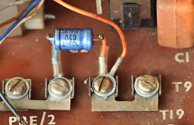
The additional capacitor in place
The ringing works as follows, and makes use of a normally undesirable effect experienced when two phones are wired in parallel as in an extension: bell tinkle. The first thing to understand is that the bell coils are wired across the supply, but there is a capacitor in series which blocks the DC current and so appears as an open circuit, drawing no current. The inductance of the bell coils ensures that none of the speech signals can pass either, so under normal conditions the bell assembly just sits there with no current flowing.
When the dial is operated on a phone with the handset lifted, two sets of contacts within the dial mechanism first short out the earpiece and microphone, and then as the dial is allowed to return, a third set of contacts rapidly disconnect and reconnect the line repeatedly, the number of disconnects being directly related to how far the dial was originally turned.
Here's what happens electrically:
Initially as the dial begins to be turned, its contacts will be closed, so the line voltage is almost zero and so the capacitor in the distant phone will be discharged.
When the dial begins to return, the contacts first disconnect the line, allowing the line voltage to rise to its maximum, causing the bell capacitor in the distant phone to charge to full line voltage through the bell coils, making the bell ping one way as it does so.
As the dial continues to return, the contacts will again close, dropping the line voltage to zero and making the capacitor in the distant phone discharge through its bell coil in the opposite direction, making the bell ping the other way.
Therefore, the repeated opening and closing of the contacts as the dial returns causes the bell to ring for as long as it takes the dial to return, so if a '0' has been dialled, the bell will ring for that duration which should be enough to get the wife's attention.
As a point of interest, with both handsets in the cradle, no current is drawn and line voltage will be at its maximum. If a handset is lifted, it will cause the line voltage to drop to 5 or 6 volts, and both bells should give a single ping if correctly adjusted. Replacing the handset will result in another single ping on the other gong as the voltage once again rises. This almost replicates what the dial contacts do, so repeatedly dabbing the cradle switch will ring the bells, but that's an annoying thing to do, right?
All that's left to do now is to tidy up the wiring, and train the wife to perform the appropriate action upon hearing the bell ring. Perhaps you could introduce your grandkids to the wonders of a rotary telephone!
Recreating that Original GPO Dialling Tone
One very minor point about making the intercom described above is that when you lift the handset, there'll be no dialling tone as this would have been generated by the telephone exchange; you'll hear nothing, apart from you, wheezing into the mouthpiece.
For a little more authenticity, you could knock up a simple circuit to create a dialling tone; I'm not talking about the two-tone sound typical of the more recent times, but the old purring GPO tone, which also happens to be much easier to create.
The local exchange would have generated this sound either by using motor-driven contact sets or a vibrator unit. The output was typically a square wave at a frequency of 33Hz or thereabouts; I remember this sound well from when I used the phone box outside my house in the late 60s & early 70s.
The circuit below uses the ubiquitous NE555 timer chip, and using the readily available values shown on the diagram and a single 2·2µF timing capacitor, my unit outputs a square wave at 32Hz with a 1:1 duty cycle, pleasingly close to the original specification. However, I felt the tone sounded better slowed slightly, which is why there's a 0·22µF capacitor shown in parallel to it on the diagram, to reduce the frequency a tad.
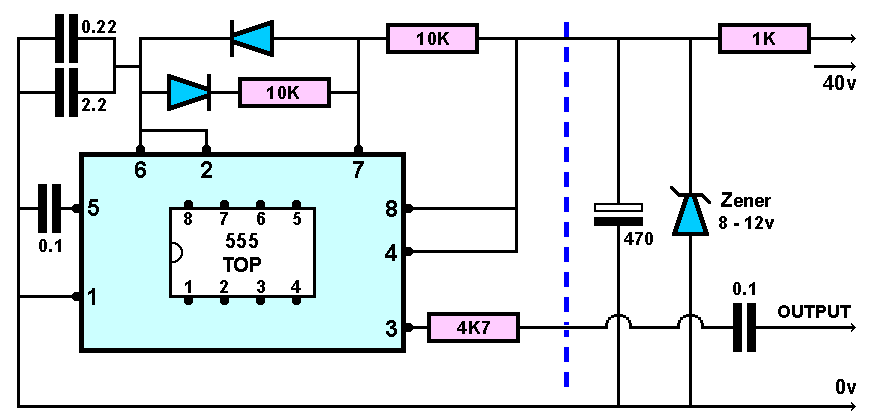
Circuit to produce the old-style GPO dialling tone
CIRCUIT NOTES:
The section to the right of the blue dotted line is to supply 12 volts to the 555, assuming it'll be connected to a 40 volt supply as mine is. The 12 volt Zener & 1KΩ resistor shunt the voltage to around 12 volts, the maximum permissable for the 555 being 15 volts.
The 0·1µF capacitor on the output allows the output stage of the 555 to operate in true push-pull, as the chip has a single-rail supply; the capacitor doesn't need to be any larger than this. The output is fed into the mains winding of a 240v:30v transformer, and the 4·7KΩ resistor in series damps the tendency of the capacitor to ring with the transformer's inductance, which may create audible artefacts.
The steering diodes can be practically anything, but the good old 1N4148 would be a sensible choice if you have them available. The 2·2µF and 0·22µF capacitors should be film types but if an electrolytic is chosen, be sure to observe polarity. The 0·1µF capacitor connected to pin 5 decouples it as regards noise, and can be a disc ceramic type.
There are a few ways the resulting tone could be injected into the telephone circuit, but I use a small 240v to 30v mains transformer, with the output of this circuit connected to the mains winding. The 30v winding is placed in series with the supply to the telephones, its DC resistance being negligible. Any transformer with a similar turns ratio will work equally well.
This results in a dialling tone of about the right volume to my ears, but if the tone is too loud, a higher resistance could be placed in series with the output to reduce its level; too quiet, and you could try a transformer with a higher voltage secondary winding.
One slight drawback of injecting a dialling tone like this is that it'll be there all the time, even when trying to speak, which might get tiresome after a few seconds so some relay switching is in order to direct the dialling tone as required.
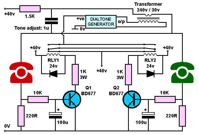
Circuit for detecting an active phone, and directing the dialling tone
CIRCUIT NOTES:
A lifted handset is detected by the 4·4 volts or so developed across the 220Ω resistor (at 20mA) in the phone's negative power supply line, this being fed to the base of a darlington transistor via a 10KΩ isolating resistor, turning it on and activating its associated relay. These 220Ω resistors are also beneficial in improving current sharing between the phones. The optional 4·7µF capacitor mentioned earlier linking the tops of these resistors isn't shown on this diagram to avoid clutter, but does improve audio transfer.
The 1µF "Tone adjust" capacitor is connected across the secondary of the dialling tone injection transformer, and although optional, does take the harshness out of the dial tone. I have found this value results in a sound closest to the original as I remember it, but there is room to experiment.
I used components from the junk box, including the 24 volt relays; the 3 watt 1KΩ resistors are to drop the excess voltage to limit heating in the relay coils, considering the 40 volt supply. The BD677 transistors were also in the junk box so I used them, but other darlington types could be used. The 100µF capacitors are optional, but when a handset is lifted, it creates a short delay before the dialling tone begins, for added authenticity. It also has the benefit of stopping the relays chattering as you dial.
Tracing the path of the current through the relays' contacts, it can be seen that power to the dialling tone generator is disabled with both handsets in their cradles, and also when both are lifted; however, if only one handset is lifted, the dialling tone generator is powered, and the tone is heard in the earpiece. Cunning, eh??
Dismantling, Servicing & Reassembly
There may be a requirement to dismantle one of these telephones, to perhaps replace a faulty part or simply to give the components a good clean. For cleaning, I recommend that all the modules are removed, and in the order listed to reduce the unit to a bare chassis. Reassembly of each component is also covered to highlight any points which should be considered, but is best done in the reverse order of the dismantling, which gives you more room to work.
Step 1:
Removing the Circuit Board
Disconnect all leads from the circuit board by loosening the screws and sliding out the spade connectors. Some leads will be terminated with a ring, in which case the screw will need to be removed to disconnect the lead; it's a good idea to replace the screws so none get lost.
The single central screw holding down the circuit board can now be removed, allowing the board to be lifted slightly at the terminal edge, and carefully pulled out. Note the slots in the front of the board, and how they fit with the vertical metal parts of the chassis, and also the lever and spring assembly fitted to the top of the board's cradle switch, and how that fits into the cradle lever.
I suggest that once the circuit board has been removed, the securing screw is screwed back into its hole in the chassis, to prevent it getting lost.
Circuit Board: Cleaning & Maintenance
A soft brush can be used to gently remove any accumulated dust from the board, but be careful in the vicinity of the selenium diode stack, as the plastic case can be very brittle and contains a small but powerful spring. However, should this device be accidentally damaged, it won't affect the operation of the phone as it is part of the now redundant regulator unit.
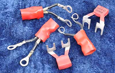
A selection of type 205 rectifiers
The small rectifier connected to terminals T1 & T2 (rectifier element No.205) can be removed and tested for correct operation by passing a 5mA current through it and noting the voltage drop across it using a multimeter; the test should be conducted in both directions. The voltage should read between around 0·5 volts and 0·8 volts. An appropriate testing current can be derived from a 12 volt DC supply with a 2·7KΩ resistor in series to limit the current to the small value needed.
Any reading, in either direction significantly below 0·5 volts suggests the unit is losing its rectifier properties, and a reading of over 0·8 volts or so suggests the rectifier's internal resistance is beginning to rise. In both cases the rectifier should be replaced with a known good unit and fitted to the circuit board.
The screws on the terminal strips can be unscrewed about half way, and a drop of contact cleaner/lubricant carefully applied to each pad and around the screw threads, being careful not to flood the area, then screw them back in. This should help prevent any further corrosion in this area.
Refitting the Circuit Board
Slide the board inwards at an angle, ensuring the slots in the board fully engage with the slots in the metal uprights; watch the cradle switch mechanism to ensure it doesn't get snagged and that you haven't got any of the leads trapped, or left the fixing screw in the chassis. The lever bar of the cradle fits into a U-shaped channel in the microswitch lever as in the photo below.
Circuit board locating notches |
How the cradle lever locates |
Once the board is correctly located and its mounting hole aligns fully with the threaded hole in the chassis, fit and tighten up the retaining screw and reconnect the dial and bell connections, along with any others needed at this time.
For easy reference, below are the diagrams from earlier, showing the handset and bell connections, but for clarity, no straps or line connections are shown. Strap locations and incoming lead positions will depend on the intended use of the telephone.
Showing the connections for the dial assembly and the bell
Showing the connections for handset and sound-limiter MR2
Step 2:
Removing the Dial Unit
Ensure the five dial assembly leads have been disconnected from the circuit board. Loosen the dial fixing screw a couple of turns; it isn't necessary to completely remove it. With the screw loosened, the dial unit can be pivoted upwards, allowing the two locating tabs on the underside to disengage from the slots in the gong link plate.
Dial fixing screw |
The dial's lower locating tabs |
Remove the dial unit taking care not to pull on the five leads as you withdraw them from within the cradle support.
Dial Unit: Cleaning & Maintenance
Fully dismantling the dial unit is fiddly, and should only be done if there seems to be a major problem; a broken unit, while sometimes repairable, is usually best replaced. However, some basic servicing is possible, so the unit can be opened up to allow this.

Removing the dial finger plate |
Removing the dial number disc |
Remove the dial's finger plate by first removing the central clear plastic cover and any paper number label under it; to avoid damaging the cover disc, use a bit of adhesive tape to pull it out, rather than trying to lever it out. Once out, this allows access to the central screw, the removal of which allows the finger plate to be lifted off for cleaning.
To remove the number disc, carefully remove the curved spring wire clip by bending it slightly inwards to release one end from its tab, which will then allow it and the number disc to be lifted off for cleaning, while revealing the internal mechanism. Note that the clip can only be refitted one way round due to the uneven shape.
A single spot (not a full drop) of sewing machine oil can be applied to the accessible bearings, with a very small amount on the worm gear of the governor unit. Be careful to mop up any spills, and be very careful not to over-lubricate, as this may find its way onto the contacts to the rear.

Showing the dial mechanism |

Close-up of the dial's speed governor |
The speed governor works as follows: as the governor shaft is spun during dial release, a pair of weights are forced outwards against the inside of a friction cup. If there's a tendency for the governor to spin faster, the weights are forced outwards harder, the extra friction counteracting the speed increase.
Check the inside of the friction cup for accumulated debris, and if any is visible, carefully clean it out with a cotton bud or a piece of kitchen roll wetted with isopropyl alcohol. The slightest smear of oil could be applied to the inside of the cup, but whether this is necessary or even desirable is a subject for debate; I don't lubricate mine.
Once the governor cup has been cleaned and the dial mechanism lubricated, the number disc and finger plate can be refitted to the front of the dial unit, followed by any telephone number label and its protective clear plastic cover.
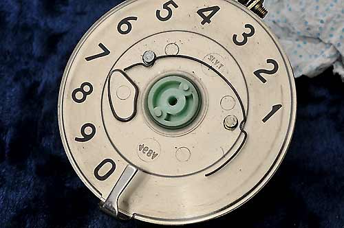
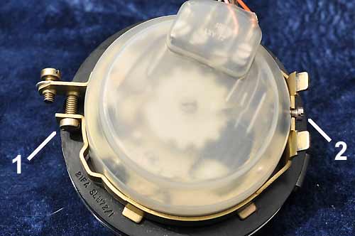
Next is to open up the rear of the dial unit to allow access to the contacts. The protective nylon dust cover is held in place by a large circular clamping ring, which can be released by undoing the large clip tightening screw (1), and removing the small locating screw (2) opposite this. The clamping ring and plastic dust cover can now be eased off.
Removing the dial's rear dust cover |
Showing the dial's contacts |
The small screw (2) locates both the plastic cover and the metal clamp, so when reassembling, ensure the hole in the plastic cover aligns with the hole in the dial body, and the notch in the clamping ring aligns with those before trying to replace the screw.
Dial lead locations
The surfaces of the three sets of contacts may have accumulated some blackening, especially on a well-used phone, so could benefit from being cleaned.
Don't use any files or abrasive paper! A good method is to moisten a piece of paper or very thin cardboard with contact cleaner/lubricant and gently pull it through each set of contacts while applying a small amount of pressure to keep them closed. Continue to do this until no more blackening comes off on the paper. Remove any remaining contact cleaner from the contact surfaces.
Should you wish to dismantle the dial unit further, the photo shows the correct locations of the dial leads, in case you forgot to make a note of it.
Refitting the Dial Unit
Once the dial unit has been fully and correctly reassembled, carefully thread the dial unit's wires back under the cradle support so they are in position to be reconnected to the circuit board. Locate the dial's pair of locating tabs in the appropriate slots on the gong link plate, and pivot the dial unit rearwards and down until the fixing screw engages with its slot. Tighten the screw when in place; there is some scope for adjustment here if the face of the dial doesn't sit parallel to the case's front.
Step 2:
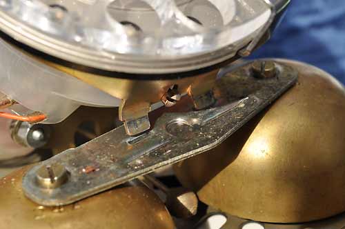
Removing the Bell Gongs
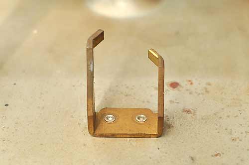
The bell gongs can be removed by unscrewing the top screw securing each one, and then simply lifting off the components, which will essentially now collapse into a pile of bits: the gongs, the gong link plate, the support pillars and the screws.

The gongs in place |
The components of the gong assembly |
Bell Gongs: Cleaning & Maintenance
These components can be cleaned in water and washing-up liquid, and once cleaned sufficiently, should be placed somewhere warm until completely dry.
Reassembling the Bell Gongs
When reassembling, Take note of the way the gong link plate is orientated, with the embossing going downwards and the angled edge facing the front of the phone; it doesn't seem to matter which side each gong is fitted. The conical support pillars should have the smaller end facing upwards.
It can be quite a fiddle positioning a support pillar, sitting a gong on the top of it and then trying to thread the long screw down through the link plate, gong and support pillar and on into the threaded hole in the chassis, but it can be done. I assemble one gong first, but leave the screw loose; this secures that bit but allows enough slack for the second gong to be fitted.
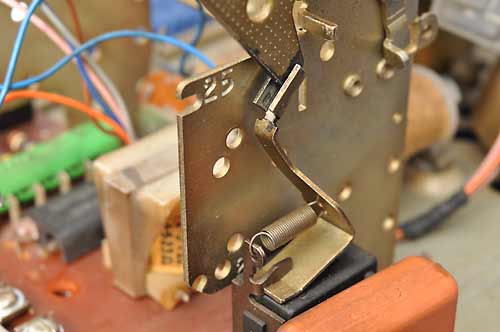
Once reassembled, don't fully tighten up the gong screws just yet, just nip them up for now. Assuming the bell actuator has been fitted (which it should now have been), we now have to set a working clearance between the actuator's striker ball and the gongs.
The bell's striker can be gently moved one way or the other, the slight magnetism holding it in whichever direction it was moved. The bell gongs have an off-centre mounting hole, meaning that as a gong is rotated, the skirt's distance from the striker changes.
With the striker ball moved to one side, adjust that gong so that there is a small but visible gap between the striker ball and the gong's skirt: around 1mm or slightly less seems ideal; the ball shouldn't actually be touching the gong. Move the striker the other way and adjust the other gong in a similar manner. Tighten the gong screws and recheck the clearances.
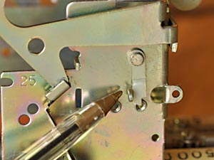
Operation can be checked by flipping the striker bar one way and the other with a pencil and checking that the gongs ping freely. If they fail to ping, the clearance is too wide.
Step 3:
Removing the Bell Unit
The bell unit can be removed by undoing the two retaining screws on the underside of the chassis; they are designed to remain in the chassis but can be completely removed if wished. In particular, keep an eye out for the two plastic spacers fitted between the phone chassis and the bell unit which are necessary to create the correct operating clearance.

Bell unit mounting screws and plastic spacers |
Bell unit's rear locating tabs |
The other end of the bell mechanism is located on a pair of odd little metal protrusions: the longer one hooks in behind the bell unit's frame, and the frame rests on top of the shorter one. Some careful manipulation may be required to unhook the bell unit from the longer tab, more so to refit it.
Bell Unit: Cleaning & Maintenance
Carefully brush off any dust on the unit, paying attention to the gap between the armature and the bell coil assemblies. If any of the wires seem insecure, re-solder them.
If particularly grimy, the bell unit can be brushed in water with a small amount of detergent and then thoroughly rinsed; I've done this, but don't recommend it. However, if there really is a need, ensure that afterwards it is placed somewhere warm to completely dry for a week, or better, connect each coil in parallel and connect a 24 volt DC supply for a few days, letting the heat generated within the coils do the drying. All moisture must be removed from within and under the coils, or corrosion may occur.
If you are feeling brave, you could attempt to adjust the armature clearance. Bob has detailed instructions on how to do this here:
Bob's telephone files - bell adjustment.
Refitting the Bell Unit
At this point there should be nothing else fitted to the metal telephone chassis, the bell unit being the first component to be fitted; this is useful as it allows the room needed to move the unit into position.
Place the bell unit roughly into position, noting the position of the screw holes. Carefully move the assembly around until the longer of the rear locating tabs has located above the actuator's main bar, and allow the assembly to sit on the top of the shorter tab, locating it in the vertical plane.
Screw both screws fully into the telephone's chassis from underneath, and place the plastic spacer washers onto them. With the bell unit correctly positioned, carefully tighten the two screws, a little at a time, alternately; don't fully tighten one first, in case the bell unit is misaligned.
Step 4:
Cleaning the Chassis
With the above components removed, you will now have a bare chassis ready to be given a good clean. If you intend to use water, the four rubber feet and the oval grommet should be removed; it can take quite a bit of finger force to do this, but is necessary to ensure that no water gets trapped between them and the metalwork.
The chassis can then be scrubbed using water and household detergent to remove the decades of accumulated grime, but be sure to put the cleaned chassis somewhere warm for a day or two to ensure all the water has evaporated, or there's a risk of rust forming where is has been trapped, for example under riveted metalwork.
Once the chassis is completely dry, the feet and grommet can be replaced.
To reassemble the telephone, work backwards from this point by first fitting the bell unit, followed by the gongs, the dial assembly and finally the circuit board.
Messing About Simulating Longer Lines
The two phones in an intercom will be almost certainly be connected by a pathetically short length of line, but the units were intended to work well with far longer line lengths, several miles in some cases. I like the idea of making the telephones work for their living, so I decided to have a mess around trying to simulate a long telephone line.
The first job was to try to find some information on typical telephone line characteristics. After much frustrating searching, rejecting of cookies, declining of multiple offers of useless merchandise and idiotic chat boxes, I managed to locate or calculate the following data for a 0·5mm diameter copper pair telephone line, as used up to a few miles from the exchange:
| Loop resistance per Km | Capacitance per Km |
|---|---|
| 168Ω | 0·05µF |
I've seen mention of inductance too, but as the wires run parallel to and close to each other, inductance should pretty much cancel out, so I'll ignore it for now until I can find reliable data.
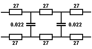
Simulating a 1Km line |
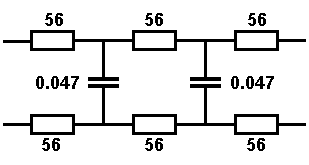
Simulating a 2Km line |
The diagrams above show the values required to simulate both 1Km and 2Km lengths of line, and using preferred values for the components, both examples come out close to that specified. If wished, these simple circuits could be constructed on a small piece of circuit board and fixed within the telephones; apart from simulating a long line, the circuits would also help to ensure good current sharing between the phones if used for an intercom as detailed earlier.
In a true length of line, the resistance and capacitance is distributed evenly along the length of that line, so a low component count may not be an ideal representation. A closer simulation would be to have multiple resistances in each leg of the simulated lines, with many low value capacitors across the lines at regular points totalling that required. Obviously there's a limit to how many resistors and capacitors is practical, but the diagram below may prove to be a closer simulation than the previous one without getting silly, if you wish to experiment.
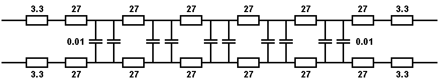
More complicated 2Km line simulator circuit
0·01µF is a common value of capacitance so I've used 10 of these to total the 0·1µF expected. I've used 27Ω resistors for the bulk of the resistances, with four possibly unnecessary 3·3Ω resistors at each end of both lines to bring the total resistance close to that expected: this combination comes out at about 337Ω, close enough.
We could go further and have dozens of resistors and dozens of tiny capacitors in our line simulation circuit, but by then it may be simpler to just buy a couple of miles of telephone cable and use that.