This Coxparo Thing
Some years ago I managed to acquire an odd bit of equipment which was found laying around inside a shed at an old, remote farm. The last time I looked, doing an Internet search for 'coxparo' turned up absolutely nothing, so it became a bit of a mission of mine to discover what this device is, and how it would have been used. This page was created so that if someone now searches for 'coxparo', they would find this page and hopefully find the information here to be of some use.
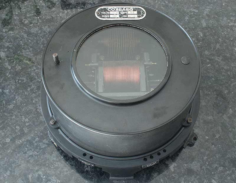
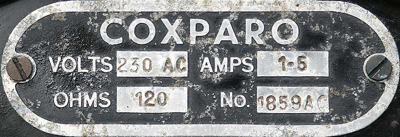
The complete Coxparo regulator unit
As you can see, the case is made of black Bakelite, there is a rotary control poking through the top on the left-hand side, and it has that rather interesting circular window offering an enticing glimpse into the interior of the device. Excluding the mounting flange around the base, the unit measures about 8.5 inches across.
Turning the unit over, the rear looked equally interesting in a vintage sort of way and the image below is of the rear of the Coxparo regulator:
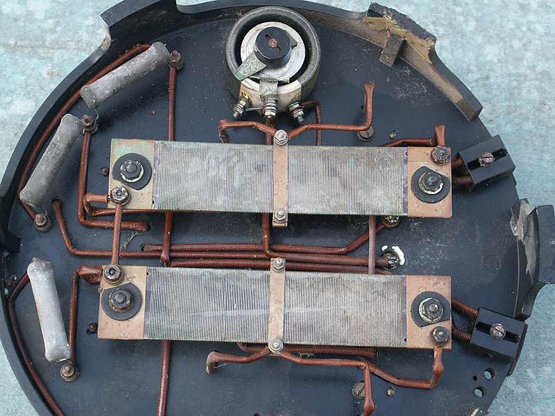
Rear of the Coxparo regulator unit showing resistors
This unit was intended to be mounted on a vertical surface such as a wall, although in this example the 3 mounting flanges have been broken off. The hot-running components on the rear are positioned to aid cooling with the help of the gaps around the base which allow a good air flow. You can see the two large flat centre-tapped 60Ω wire-wound resistors, a rotary 700Ω wire-wound potentiometer at the top (which is operated by the spindle shown poking through the case earlier) and 3 ceramic 10 watt 2KΩ resistors. Closer inspection revealed that there should have been a fourth, but it had been broken off. Of course, we also have the wiring to connect the various components together, nicely shaped and routed in a way you no longer see in modern equipment. On the right are a couple of connection blocks, pictured in more detail below:
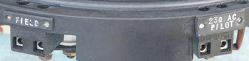
Close-up of the connections to the Coxparo unit
I believe that this unit was the control device for regulating the output of a generator, and the connections would seem to support this as the one on the left is labelled 'FIELD', and the one on the right appears to be labelled '230 AC PILOT' or 'P/LOT'. Next up is a photo of the interior of the Coxparo unit, the components behind the glass window:
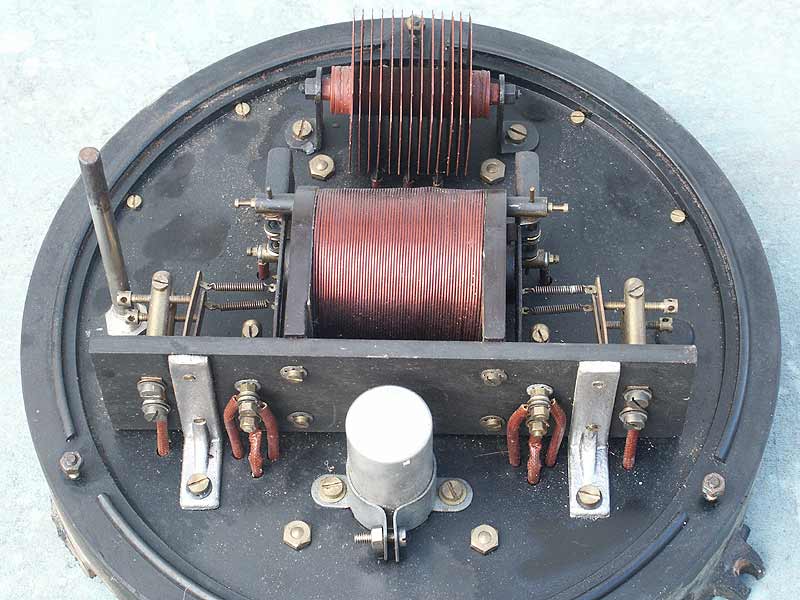
Interior components of the regulator unit
The connection to the '230 AC' terminal feeds the full-wave selenium rectifier at the top of the photo via the 3 (should be 4) 2,000 ohm grey resistors fitted on the back, with a pair of those resistors in parallel in each leg of the AC supply, with the resultant rectified supply charging the 8µF 500V capacitor visible at the bottom.
The rectified and somewhat smoothed supply thus produced passes through the wire-wound potentiometer and then through the centrally mounted component with the coil; that's it for that part of the circuit. Tests showed that the capacitor had dried out completely and no longer exhibited any significant capacitance, so I lashed another across temporarily so I could do some tests.
Using an isolating variac, once a sufficient voltage was applied, the coil energized and pulled in the pair of levers on each side of the coil, opening the contacts attached to them. I'm not sure why there was a glass window fitted, but perhaps some slight sparking of the contacts was visible during operation and gave an indication that the unit was working correctly.
Below is a closer photo of the contacts on one side of the coil, showing the construction:
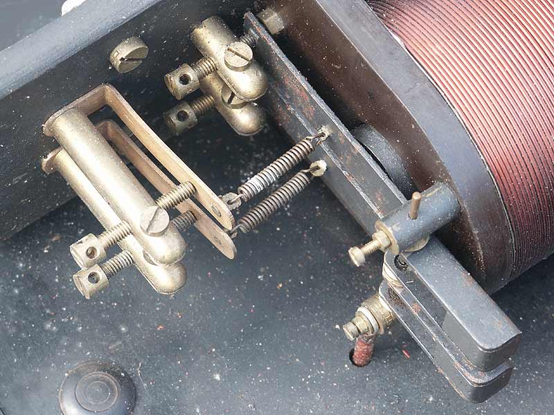
Close-up detail of two contact assemblies
As can be seen, the construction is quite delicate, with small brass adjustments to facilitate fine control. One point of interest is the way the contactor arms have a weight at the outer end; I don't know whether this was to help it vibrate to assist partial field coil energisation, or to damp out such vibrations. During tests it was apparent that the capacitor value wasn't large enough to provide perfectly smooth DC to this assembly and the resultant DC had a fair amount of ripple on it which did indeed cause the contact arms to vibrate when they were on the point of making or breaking contact, so this is most likely intentional.
The 4 sets of contacts and the 2 flat resistors are connected to the 'FIELD' terminal, which would have been connected in series with an external field coil supply and the generator's field coils. The contacts are arranged in such a way that different sections of the resistors could be brought into circuit, allowing a total of 5 different resistance values (including zero) to be selected to go in series with the generator's field winding, depending on the voltage supplied to the coil. Each of the 4 contacts is under slightly different tension, so as the magnetism increases in the coil due to an increasing generator output, different sets of contacts open, allowing additional sections of resistance to be brought into circuit. The minimum resistance is essentially zero with all 4 contacts shorting out their own section of resistance, and maximum resistance is 120 ohms with all contacts open. There is no facility to open the field coil circuit completely.
My feeling is that the source of the field current might have been a permanent-magnet exciter unit mounted on the same shaft as the main generator, or even a lead-acid battery.
Diagram of the resistances & switching inside the unit
Diagram of the coil energising components
To me, this is an interesting component, very well made and designed to do a precision job at a time when the electro-mechanical system we see here was the only decent way to get the job done. These days with semiconductor regulators, such regulation is simple. If you know anything about this unit, such as the type of generator it would have been used with, and the type of field power supply used, please let me know, so I can add further information here.