The Nature Of The Quest
I wanted to heat my water by using solar photovoltaic panels to power the immersion heater, but without the expense and complication of buying one of those dodgy foreign-made inverters. Some may argue that it would be better to use solar thermal panels to heat the water, but this requires additional plumbing, a pump to circulate the water and I'm not convinced it's any more efficient. What I've developed here is a very simple system needing no changes to the existing plumbing and no expensive electronics and software. The simplicity and therefore cheapness of this design are its primary features.
Initial Ponderings
My initial idea was to connect the solar panels directly to the immersion heater, bypassing the considerable expense and complication of the usual electronics. Once I researched and understood the characteristics of solar panels and started doing some calculations, I realised that a direct connection to the immersion heater wasn't going to heat the water significantly in anything other than full sunlight.
The reason for this is the way solar cells operate: once sufficiently illuminated, the output voltage remains fairly constant irrespective of how bright the sun is. The output current, is, however, highly dependent on illumination, ranging from next to nothing in poor lighting to the maximum rated output in strong direct sunlight. This apparent current limiting impacts power delivery severely, and if an attempt is made to feed the power into a fixed load resistance such as an immersion heater, efficiency will be poor at lower light levels.
I can demonstrate this effect using a bit of maths: take, for example, a situation where the solar panel array is in relatively low light, and can only produce 1 amp of current. If this were connected directly to an immersion heater with a typical resistance of 20 ohms, Ohm's Law dictates that the 1 amp of current available would only develop a voltage of 20 volts across the load, developing a pitiful 20 watts of heating. (Power = volts x amps.) However, the solar panels could be capable of producing that 1 amp at a voltage of, say, 140 volts if the load were better matched, meaning that under optimum loading conditions, 140 watts would be available to heat the water. (140 volts x 1 amp) As can be seen, mismatching the load represents a significant loss of efficiency under poorer lighting conditions, which is exactly when you'd want to squeeze every bit of power from those panels.
The table below shows the effect of the load mismatch, based on a typical immersion heater resistance of 20 ohms. (Changes in voltage with illumination have been ignored for simplicity.)
| Current available | Power available | Power into heater | Efficiency |
|---|---|---|---|
| 0·5A | 70W | 5W | 7·1% |
| 1·0A | 140W | 20W | 14·2% |
| 2·0A | 280W | 80W | 28·5% |
| 3·0A | 420W | 180W | 42·8% |
| 4·0A | 560W | 320W | 57·1% |
| 5·0A | 700W | 500W | 71·4% |
| 6·0A | 840W | 720W | 85·7% |
| 7·0A | 980W | 980W | 100% |
So What Can Be Done About This?
The established way to deal with this is to use some commercial product such as an inverter with maximum power tracking software to power the immersion heater. This is expensive, complex and in this instance, unnecessary.
One way we could make use of whatever power the solar panels can generate would be to have a variable load resistance, chosen to best match the output of the panel at a particular moment. This would suggest the 20 ohm load for bright sunlight, rising as the light weakened, to around 140 ohms when the panels can only supply 1 amp of current.
Evidently this is impractical when using immersion heaters, although having an option to wire multiple heaters in series would improve power transfer somewhat under less than ideal lighting conditions. This is not an elegant solution and would require control circuitry to do the switching, quite apart from the unlikelihood of physically fitting several heaters into a tank.
Introducing Andy's PowerDump Technology
OK kids, you can stop giggling at the name now, this is a really neat, cheap and simple solution.
It is known that for efficient power transfer, we need to be operating the panels close to their maximum power voltage.
So imagine this for a moment:
You have your solar panels connected to an enormous bank of capacitors, a voltmeter monitors the voltage across the capacitor bank, and a switch connects the capacitors to the immersion heater. You know the optimum voltage to run the panels at, as it's given in the specifications.
Initially the switch is off and the voltage rises due to the capacitors being charged from the panels. When the voltage climbs to just above the peak power voltage, you operate the switch, dumping power from the capacitors into the immersion heater. You watch the voltage as it falls, and when it has fallen to just below the peak power voltage, you open the switch, allowing the capacitors to charge up once again, until the voltage again rises to just above optimum voltage, whereupon you switch on the switch again, and so-on for ever. Lower light levels simply mean the capacitors take longer to charge, but whatever power is available is harvested, stored and eventually dumped into the water.
This would indeed work. There are a couple of problems with this idea: getting a capacitor bank large enough to make the switching requirement slow enough to perform, and finding someone daft enough to stand there all day watching a meter and operating a switch.
Luckily, electronics can come to our aid.
The capacitor bank can now be reduced to a sensible size as switching frequency is no longer a major concern, the meter-watching can be done by a comparator with some hysteresis thrown in to produce the upper and lower limits of the 'dumping window', and the switching can be done by a MOSFET. Beautifully simple, using nothing more than basic electronics with not a line of code in sight, and costing less than fifty quid including a case.
Real World Solar Panels: Voltage Variations
Unfortunately, things are rarely as straight-forward as we'd like them to be, and solar panels are no different. Here are some real-world solar panel specifications courtesy of Bimble Solar
| Power Output (Pmax) | 295 watts |
|---|---|
| Voltage at Pmax (Vmpp) | 30·93 volts |
| Current at Pmax (Impp) | 9·54 amps |
| Open-Circuit Voltage (Voc) | 37·18 volts |
| Short-circuit current (Isc) | 10·08 amps |
| Temp. Coefficient Pmax | - 0·4 % per degree |
| Temp. Coefficient Voc | - 0·3 % per degree |
One of the issues is the temperature coefficient, as this causes the panel's voltage to change with temperature. This voltage change can be calculated using basic arithmetic, using the data from the specifications.
At 25°C, (the standard measuring temperature) five of these panels in series would produce around 154 volts at the maximum power point and an open circuit voltage of around 186 volts.
At 10°C, which is more typical of UK Winter temperatures, things change a bit, producing around 164 volts at maximum power, and an open circuit voltage of around 194 volts.
At 40°C however, things go the other way with only around 145 volts at maximum power, and an open circuit voltage of around 178 volts.
Another 'feature' to contend with is the lower voltage available under lower levels of illumination. Both of the above conditions can be compensated for by having an option to shift the window down about 15 - 20 volts (for 5 panels in series) to improve power transfer under very hot conditions or on overcast days. A simple front-panel switch labelled 'normal' and 'low' would be an elegant solution to this, and simple to include in the voltage monitoring circuitry.
Design Thoughts For The PowerDump Prototype
I decided that an array of 5 panels similar to that featured above wired in series would be suitable, requiring capacitors of a 200 volt rating, above the maximum they would be likely to receive even in cold weather. Too small a capacitance would lead to a high switching frequency, which if too fast could lead to heating losses in the capacitors and the MOSFET, so a decent amount of capacitance would be preferable to slow things down, with the benefit of sharing the discharge current between many capacitors.
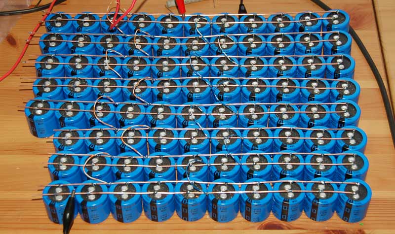
A nice collection of 1200µF 200v capacitors being prepared for PowerDump duty
30 of the capacitors as pictured above wired in parallel will give somewhat over 30,000µF of capacitance, suggesting a power dump duration of around 60 - 70 milliseconds or so into a 20 ohm load, nicely relaxed, although the system would work fine with far fewer. I also intended to have an LED indication of when a dump was taking place, and at this duration, it would be easily visible.
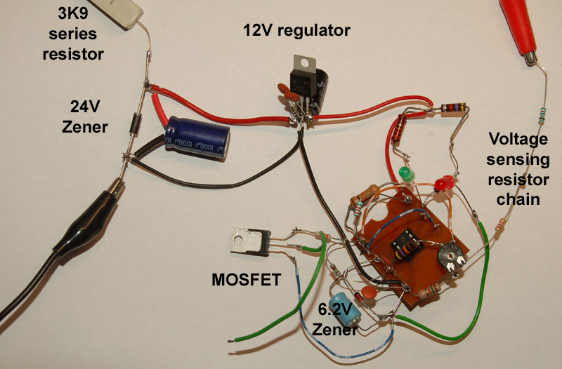
The power for the switching and monitoring circuit would be taken from the panel supply making it completely solar-powered. The high voltage on the capacitors can be reduced to 24 volts using, say, a 5·6K resistor in series with a 24v Zener diode, the output of this feeding a 7812 regulator to provide a stable 12 volts to the main circuitry.
For sensing the voltage accumulated on the capacitor bank, half an LM393 dual comparator could be used, with a voltage reference connected to the -ve input. A resistor chain connected across the capacitor bank can sense a fraction of the stored voltage and input this to the +ve input, comparing that to the reference, with a resistor connected between output and the +ve input to provide the required degree of hysteresis.
The output of the comparator takes the form of a current sink, and when on, this would sink current passing through the MOSFET's gate feed resistor, pulling the gate to 0 volts, holding it in the cut-off condition. As the voltage sensed at the comparator's -ve input rises above the reference voltage, the comparator's output would switch off, allowing the full 12 volts to appear at the gate of the MOSFET via its gate resistor, turning it on resulting in a power dump into the immersion heater, until such time as the voltage across the capacitor bank dropped sufficiently to turn on the output of the comparator, once again shutting down the MOSFET.
Experimenting With Circuits
Now I had the idea for the circuit worked out in my head, it was time to slap some components together to test my theory and calculations. My favourite way to do this for simpler circuits like this is to construct a working circuit birds-nest style on the bench, and while it looks untidy, it is very easy to change values to get things working the way I want them.
Initial circuit testing, birds-nest style
To test and adjust the operation of the circuit I used an isolating variac feeding a bridge rectifier and capacitor to mimic the output of the solar panels, which allowed me to finalise the resistor values in the divider chain and to set the hysteresis to give roughly a 10 volt switching window. A preset potentiometer was included to allow the window to be shifted up or down in voltage to enable a range of panel specifications to be accommodated.
The second comparator in the package is used to provide an indication of what the circuit is doing, by illuminating a green LED while the capacitors are charging and a red LED when the circuit is dumping the charge into the water heater. This is done simply by borrowing the voltage reference and comparing this to the main comparator's output voltage. On test, the whole circuit works very well, so it's now time to do a bit of component refining and to get physical with the prototype.
Building The PowerDump Prototype
My PowerDump controller went through several stages of development as I dreamt up new features and discarded unnecessary ones, but these changes were condensed into the Mk1 and the Mk2 which are finished and fully functional units.
The Mk1
The first job I wanted to tackle was mounting the capacitors. I happened to have some pieces of copper-clad board just large enough to mount 15 capacitors, arranged in 3 rows of 5, so I decided to construct 2 such boards of 15 capacitors which would fit into the case I had chosen. Unfortunately not glassfibre laminate, but keeping creep distances in mind this would suffice for the prototype.
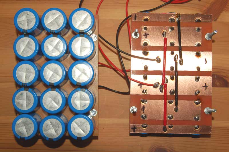
Capacitors mounted on their circuit boards
Fast-forwarding a fair bit, I designed, drilled, etched and built a circuit board for the PowerDump controller, and then as so often happens with me, I decided on some additional features I felt would be useful, which had to be retro-fitted.
The plan would be to use an Economy 7 hot water tank which I already have, which features an upper and a lower immersion heater. I felt that prioritising heating the water in the small topmost part of the tank would be useful especially if direct sunlight was in short supply, so at least there would be a hope of some warm water.
Once the sensor by the top heater indicates the tank is up to temperature (perhaps 55°C), the unit then diverts power to the lower heater to begin heating the remaining main body of water.
A sensor fitted at the lower heater location allows the unit to cease heating once the entire tank has heated up to its target temperature (perhaps 75°C), to prevent the water getting excessively hot or boiling during prolonged sunshine.
This additional sensing and diverting circuitry was built on a second board, comprising 2 comparators for the 2 heat sensors, and 2 more comparators driving a pair of reed relays to divert the gate voltage to one of two MOSFETs depending on which immersion heater required power at that time.
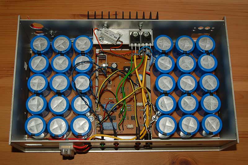
Completed PowerDump Mk1 prototype, tested and ready for service
Above is the completed PowerDump Mk1 prototype. The 30 capacitors are the most obvious feature, but between them can be seen the 2 circuit boards, the larger rear one being the PowerDump controller itself, and the smaller nearer one being the heat sensor and diverting circuitry which was added later to the unit, with its 2 blue reed relays nicely visible. At the rear of the case can be seen the dropper resistor mounted on a heatsink, along with the 2 power MOSFETS. This degree of heatsinking is unnecessary, but as the heatsink was fitted to the case I used it anyway. The front panel has LED indication of charging, dumping, and which heater is currently active, and there are connector blocks for solar input at the rear, and for the 2 heaters on the front. Also on the front are 3.5mm jack sockets to allow the heat sensing thermistors to be plugged in.
Roll over for the Mk2!
Next we have the Mk2 version, fitted into a hearing loop amplifier case, again using an over-sized heatsink because it was already fitted.
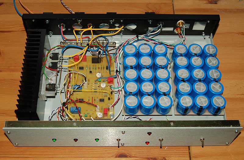
The PowerDump Mk2 on the bench being tested
The photos below show more detail of the board. I draw the tracks for my boards by hand rather than using a printed mask. While my method looks less tidy, it's a process I enjoy.

|

|
This version includes several circuit refinements: now all the electronics are on one board; component changes have been made to improve efficiency, meaning the unit only requires about 23mA to function; the use of voltage references rather than the less stable Zener diodes; glassfibre laminate circuit boards; a switch to disable heating, another switch to choose between 'auto' immersion heater selection or bottom immersion heater only, and a third switch to allow the dumping window to be shifted upwards by around 15 volts to make best use of periods of full sunshine in cold weather.
A useful change was including the facility onboard to allow conventional immersion heater thermostats to be used for temperature sensing, as well as the thermistor ones originally intended; the circuit changes are made using on-board jumpers.
During initial development, I had become a bit obsessed with thermistor sensing and the accuracy attainable, and forgot about using the conventional thermostats which in practice proved to be accurate enough.
A third MOSFET is fitted in the unit which is activated when heating is complete or disabled, allowing connection to another device, such as a battery charger or maybe a dummy load to prevent panel voltage from rising too much under what would effectively be open circuit conditions, although for the moment there is no connection to the rear panel.
Real World Testing: Proof Of Concept
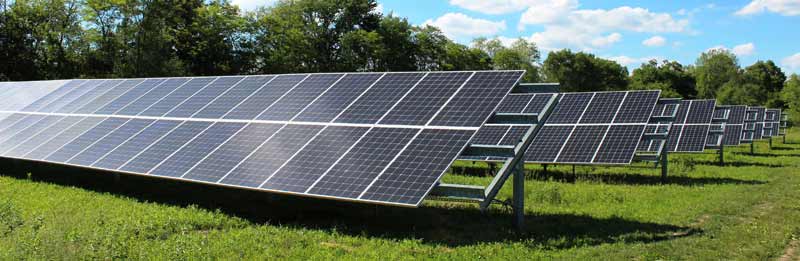
I managed to obtain 5 solar panels second-hand, and decided on a strategy to get them mounted. A risk assessment of the job indicated that the only hazards were decapitation and castration, so after some dodgy gymnastics by me and some reluctant family members, we managed to mount them on the side wall of my garage, where they would be able to get full sunshine for around 9 months of the year, for several hours a day assuming a clear sky. The following table gives the panels' specifications, should anyone be interested.
| Power Output (Pmax) | 230 watts |
|---|---|
| Voltage at Pmax (Vmpp) | 29·7 volts |
| Current at Pmax (Impp) | 7·75 amps |
| Open-Circuit Voltage (Voc) | 37·2 volts |
| Short-circuit current (Isc) | 8·3 amps |
It was mid-April 2025 when the final panel was in place and the array connected up to the PowerDump module. Unfortunately the first day after connection was heavily overcast and we had a lot of rain, which meant I had no immediate opportunity to see how the system would perform under the desired full illumination. Despite the low light levels, the PowerDump unit was still harvesting some power and dumping it into the water, which was an encouraging sign.

My panels mounted on the garage wall, fully illuminated
I did find it interesting to watch the PowerDump unit 'wake up' as dawn approached, with the green 'charge' light slowly appearing and brightening as the morning progressed, followed around ten minutes later by the red tank select light. Dumping doesn't usually begin until an hour or two later.
Practical experience has shown that the voltage reduction is much the same for lower levels of illumination as it is for hot panels, with the only time you can take advantage of the full voltage output would be for short periods of direct sunshine on an essentially cold and cloudy day, where the panels remain cold. Therefore I've found it best to de-rate the maximum power point by around 4 - 5 volts per panel, and keep it at this setting which seems to offer good power transfer under most common situations, and holds good right down to currents of 100mA or less.
My diary of how things went on initial tests
Thursday 17th April 2025
The last of the panels were mounted by late afternoon and a connection made to the PowerDump module, set to feed just the lower heater as the mains was still connected to the top one as a backup. It was encouraging to see that despite now being mid evening, power was being dumped every few seconds; the system appeared to be working as designed!
Friday 18th April 2025
Today the weather was dreadful, almost continuous rain and a heavily overcast sky. Despite this, mains power was disconnected from the top immersion heater and the PowerDump module properly connected to both immersion heaters and thermostats and configured for automatic heater selection. Despite the low light levels, the module was doing its job and collecting whatever small amount of power was available and dumping it into the top water heater. Dump frequency was around once every 3 seconds or so, but varied considerably as light levels changed, changes which weren't readily noticeable to the eye. Power available was pretty low, and was probably insufficient to even maintain water temperature, but better than nothing.
Saturday 19th April 2025
The thermometer was fitted this morning with the sensor wedged in beside the top heater to accurately monitor water temperature changes. The weather had improved a fair bit; the rain had stopped and the cloud thinned, allowing brief periods of very hazy sunshine during which the dump light was flashing several times second. The tank temperature at the monitoring point started off at 40.4°C late morning, but after a couple of hours it had risen to 45°C, finally settling at 47·1°C by late afternoon, by which time no further temperature increase was noted. Not an earth-shattering temperature increase, but still significant considering the weather.
Sunday 20th April 2025:
Tank: 38·2°C at 8:00am.
It's a clear sky this morning!
Once again I found myself awake at dawn, watching with child-like excitement as the PowerDump module slowly came to life. Overnight the water temperature had fallen due to heat losses rather more than expected, measuring 38·2°C at around 8:am with dumping occurring about once a second. By 9:00am dumping had increased to roughly twice a second and the temperature had risen to 39·2°C. I went out for a couple of hours, and when I came back at 11:00am, the temperature had risen to 47·1°C. At 12:00pm the temperature had risen to 54·3°C and by 12:30pm it had hit 57·3°C by which time the PowerDump module had switched to the lower heater. This was an excellent result, but unfortunately around this time a good covering of cloud came over, getting heavier as the day went on; this brought my hopes of preparing a heating graph skidding to a halt on its arse.
Monday 21st April 2025:
Tank: no reading taken.
Overcast sky with occasional sunshine. Been here before; I didn't bother taking any readings, so nothing more to report.
Tuesday 22nd April 2025:
Tank: 44·9°C at 8:00am.
Day started off hazy but cleared as the morning progressed. On occasions we had full sunlight which allowed some water heating to occur with the PowerDump switching to bottom heater (It does this at around 57°C) early afternoon, which was encouraging. As a side note, I had a look at the module at one point and noticed the red 'dump' light was illuminated continuously; I initially thought this was a fault until some cloud came over and the dumping became intermittent again. So - at that point maximum power was being delivered from the panels directly into the water, superb! I expect to see this happen again when we finally get a clear sky, indicating around 800 watts of power are being fed to the heater.
Wednesday 23rd April 2025:
Tank: 41·4°C at 8:00am.
Pretty cloudy with occasional bits of sun, but by 2:30pm the water temperature had climbed to 51·5°C, which I suppose isn't bad. A bit later I noticed that the module had switched to the lower heater, so the temperature had hit 57°C, slowly dropping after that.
This tank loses a lot of heat; it's one with the header tank on the top of, and integral to, the main tank. Now, it's possible a previous owner removed any insulation from this top part, but this seems to be where most of the stored heat is going is it gets quite hot, heating up the cupboard which houses the tank; useful for airing clothes, but no good for storing energy. Today, I lagged the bugger! It will be interesting to see if it makes much difference.
Thursday 24th April 2025:
Tank: 44·3°C at 8:00am.
A cloudy day with small amounts of very hazy sunshine, up until around midday when it clouded over completely with a few spots of rain. Tank showed 45·3°C when I got home at 1:30pm, slowly cooling from there. Pitiful. But it came to light that The Good Lady had used some hot water to wash dishes, so not as bad as it seemed.
Friday 25th April 2025:
Tank: 38·6°C at 8:00am.
Day started off cold and cloudy; sun started to break through soon after midday, giving intermittent hazy sunshine which improved as the day went on. When I came home at 1, PowerDump had already selected the lower heater (55° - 57°C) so quite encouraging today. By 5pm the entire tank had heated to 55·9°C, but the sky had once again clouded over. However, in the end, the best day so far.
Saturday 26th April 2025:
No measurements taken today.
Sunday 27th April 2025:
Tank: 45·5°C at 8:00am.
Day started with a clear sky, but soon around 50% cloud cover, which cleared early evening. Despite the cloud, the whole tank was heated to 59·9°C, the highest so far. This temperature was reached at around 6pm.
Monday 28th April 2025:
Tank: 51·5°C at 8:00am.
Mostly clear sky today, some light cirrus cloud. Tank reached 67·6°C by late afternoon, but then I noticed that the lower thermostat had cut out, as I had forgotten to adjust it for a higher cut-out temperature. Turned it right up ready for the next sunny day, but might even bypass it just to see how hot the water gets.
No readings taken for a while, many other things going on; however, we had a good run of sunny weather with the tank regularly hitting the high 70s and cutting out, so the system most certainly works, especially when considering the way the panels are mounted: vertical, facing the house wall. If they had been on a sloping roof, power generation would have been rather higher, even on overcast days when the panels would at least have been facing the sky, not a wall!
One point of interest is that due to the panels' vertical orientation, during the summer the sun's angle of incidence is so shallow that power generation actually reduces slightly compared to earlier or later in the year. This isn't really a practical problem, as there tends to be more sun during the summer anyway which compensates.
As things are, this setup is saving me real money as I didn't have to use mains to heat the water at all during the summer, and when the sunlight reduced in late Autumn, the system was still able to augment the water heating somewhat although most of the water heating through the Winter was by mains electricity, but this was expected.
So by way of conclusion, 5 decent solar panels mounted at an angle facing the southern sky are quite capable of heating a tank of water to scalding temperatures in a couple of days assuming reasonable sunshine, and will add some heat even under overcast conditions. Of course, more panels could be used, either to increase the current available or to increase the voltage, but in the latter case some component changes may be required to the PowerDump unit.