
Navigation
Menu
Center-fed Bent-Dipoles
Horizontal Lateral
Vertical
- OCF
Slow-Wave
Other Topics
Home
 What
Happens If...
What
Happens If...You Bend the Ends of a Dipole?
You have a space problem. You have seen examples where the ends of a dipole were bent up, down, even sideways to get it to fit. The question is what happens to the characteristics of the antenna?
This is where the modeling of wire antennas is useful.
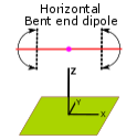
We start with a standardized half-wave dipole made of #14 American Wire Guide AWG copper wire at 1/2 wavelength high fed at the midpoint. To this we define where to make a bend along each arm by ratio. 0.5 = 50% or halfway, 0.8 = 80% toward the end, 1 = 100% or no bend.
At the bend point think of the arm having a hinge where we can define the any angle of bend for the end section. 0 degrees = straight down, 90 degrees = straight out (no bend), 180 degrees = straight up.
For each point the software calculates the optimum length of wire before bending to give lowest Standing Wave Ratio (SWR) and Ohms reactance when bent. The study is to first determine the operating conditions of the standard, unbent dipole and then progressivly shorten the arms in steps of 0.1 ratio (10%).
4NEC2 Antenna Model: Here
Figure 1 below summarizes the effects on Gain, Change in Length and SWR if the ends are bent down.
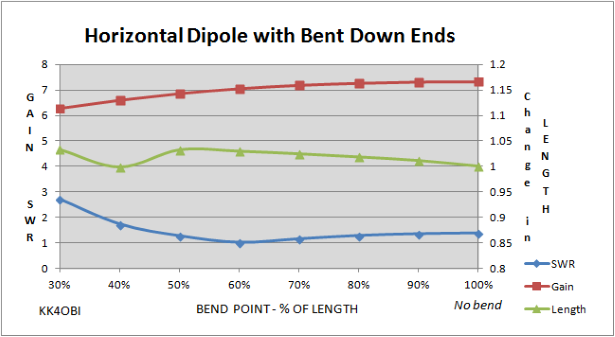
Figure 1
It is no surprise that the Gain (red) goes down as the arms are shortened. What is interesting is how little it goes down. At 60% short the gain only drops 0.3 dBi... too little to detect.
Also interesting is that the SWR (blue) for 50 ohm coax drops from 1.38:1 to a perfect 1:1 match when the bend is at the 60% point. A bend shorter than 50% does not look good in terms of higher SWR and lower Gain; the impedance (Z Ohms) drops rapidly.
The curious thing is the middle line (green). At each data point the modeling software optimizes the length of wire for lowest SWR and Reactance (j) for resonance at the target frequency. You can see that the wire length gets a bit longer (greater than 1) as the horizontal arms get shorter, EXCEPT at 40% where the resonant length strangely returns to the starting length. (I would be interested in knowing what the model is seeing there). The maximum length variance is around 4%. If you were not expecting it, I can see where this "ground interaction" at 40% would be confusing when trying to tune the antenna.
The question now is:
What happens if you bend the ends up rather than down?
This is easily modeled by changing the bend angle to 180 degrees... straight up.
In Figure 2 below are the resulting Gain, Change in Length and SWR characteristics:
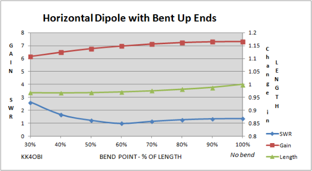
Figure 2
The answer is, when ends bent up, there is practically no difference in Gain and SWR than if bent down. However, the resonant Length (looking right to left) gets steadly shorter, then flattens past the 50% bend point. If you can figure a way to physically hold the bends in the up position, tuning should be easier. As before, bends shorter than 50% of the arm length do not look good. Doable but the losses add up rapidly.
So far you have a good idea on what to expect as you bend the ends to shorten a horizontal dipole. It is easy to see why hams have been successfully doing this.
One question remains: What changes occur in the radiation pattern?
The answer is: "not much". See below.
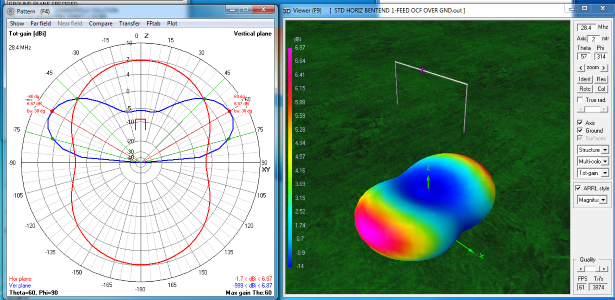
Figure 3
Figure 3. Here is the far field radiation pattern with the arms bent down at the 50% point - which is about as short as you can go with out really noticing signal deterioration.. Comparing this with the standard dipole we note that the red trace on the graph (hor plane) is slightly fatter. Only 6.87 dBi gain vs 7.32 dBi with less of a null at 90 degees; only -1.7 dBi versus -2.7 dBi. The blue trace (Ver plane) still has the signal maxima at 60 degrees (red line) down from vertical and a beam width of 30 degrees (green lines). The 3D radiation pattern of the U-shape is a little shorter and wider than the standard dipole.
With the dipole pointing both vertically and horizontally there must be some mixed polarity in the signal. This could help if you were to contact someone nearby using a vertical antenna. It also may help a bit on DX contacts where there is mixing of polarity from the signal bouncing off ionized layers.
Lets breakout the individual horizontal and vertical radiation using the capabilities of modeling software
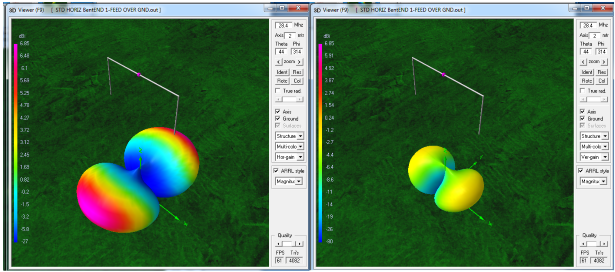
Figure 4
Figure 4. The 3D view on the left side is looking down at the radiation pattern of the center part of the antenna where most of the energy is radiated.
The 3D view on the right is the lesser radiation pattern from the vertical arms of the antenna.
Comparing the color ends of the vertical lobes on the right to the color scale, indicates about unity gain - not positive, not negative. Now look at the full 3D radiation view above in Figure 3 and note that the same unity gain is at the transition out of dark blue. You can see where the vertical radiation fills a small part of the usual null off the ends of a horizontal dipole. This "fill-in" effect is less with less bend.
The modeling software makes it clear that you can bend the ends of a horizontal dipole with very little change in antenna performance, just some retuning is required.
Dick Reid, KK4OBI at QSL.net