Navigation
Menu
Center-fed Bent-Dipoles
Horizontal Lateral
Vertical
- OCF
Slow-Wave
Other Topics
Home
On this web site, all studies about bent dipoles are based on identical standard conditions:
- Antenna feedpoint gap at 1/2 wavelength elevation over average Summerfield ground.
- Radiating arms/monopoles are made of #14 American Wire Gauge (AWG) copper wire.
- Each model is optimized at resonant frequency for Standing
Wave Ratio at 50 Ohms (SWR) and minimum reactance (j Ohms).
- All models are verified by the Average Gain Test (AGT) range of 0.95-1.05.
- Auto-segmentation is used where antenna arms are different lengths by Off Center Feed (OCF).
- Gain figures are decibels-isotropic (dBi) relative to a
lossless antenna in free space.
Home page: http://www.qsl.net/4nec2/
Characteristics
Impedance: 69.5 -j1.79 ohms (versus 71.6 -j2.68 ohms in free space)
SWR 50: 1.39 (versus 1.44 SWR in free space)
Gain: 1.57 dBi at 15 degrees elevation above horizontal (versus 2.14 dBi omni-directional in free space)
Beam Width: 40 degrees (half-power points, -3 dBi)
4NEC2 Antenna Model: Here
One of the unique characteristics of a vertical dipole is that its resonant frequency from 1/2-wavelength feedpoint and higher does not change. Rock solid. Once tuned, no retuning required whatever the height.
Close to ground the resonant frequency barely changes to be only slightly higher.
This behavior is just the opposite of a horizontal dipole where height is an everpresent factor in tuning.
Similarly, Z ohms Impedance and SWR change noticeably only when the feedpoint gap is 1/4 to 1 wavelength over ground. See Figure 1 following.
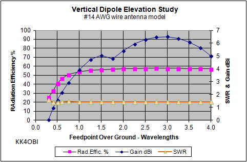
Figure 1
However, raising the dipole only 0.1-0.2 wavelength produces a nice drop, the lowest possible This sweet spot around the 1/2 wavelength feedpoint should be a consideration for near-ground installations.
NOTE:
For all studies. the feedpoint gap over ground for the standard
vertical dipole is
set at 0.5 (1/2) wavelength. This means that the bottom of the antenna is 1/4 wavelength above ground. Here impedance is the lowest, 69.4 ohms at 1.39 SWR 50.
set at 0.5 (1/2) wavelength. This means that the bottom of the antenna is 1/4 wavelength above ground. Here impedance is the lowest, 69.4 ohms at 1.39 SWR 50.
The modeling study was extended to many decades higher than shown here, but at any feedpoint height above 1 wavelength, Z is 71-72 ohms at -3.7j to -3.8 j. SWR is 1.44... the same as in free space.
The characteristics most affected by elevation are Gain and Radiation Efficiency.
Near ground Gain (Black diamond
curve) suffers the most. Zero gain. Recall that the free space gain is 2.14
dBi.
The model shows that this "unity gain" situation occurs when the
feedpoint gap of a vertical dipole is around 0.6 wavelengths (WL)above
ground (bottom is 0.1 WL above ground).
At 1 WL the gain is 3.9 dBi and still rising until 1.75 WL where the model predicts a dip before rising to a maximum at 6.5 dBi at 3WL.
Gain figures from antenna models lack meaning as the antenna gets higher because of the increasingly complex pattern of spikes, lobes or ridges in the far field radiation pattern. Suffice to say that the various values reported never exceed the maximum on the graph at 3WL.
Radiation Efficiency % (Purple squares line) also suffers near ground but recovers much more quickly (around 1 WL) and stabilizes near 57% with increasing height.
Far Field Radiation Patterns
At ground the radiation lobe a vertical dipole is aimed upward at 20° (red lines) from horizontal with a beam width of 30° (green lines), as shown below. (Defined as half-power points at -3 dBi).
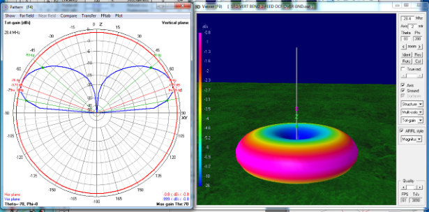

Figure 3 at ground
The radiation pattern of a standard vertical dipole at 1/2 wavelength shows elevation aimed lower...
at 15° from horizontal but with an even wider beam width of 40° due to the first ground wave.
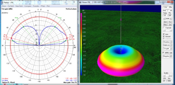
Figure 4 at 1/2WL
The strongest radiation lobe of a standard vertical dipole at 1 wavelength elevation is aimed 10° from horizontal with a much narrower beam width of 25°. There are now two ground waves apparent.
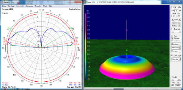
Figure 5 at 1WL
The strongest radiation lobe of a standard vertical dipole at 2 wavelengths elevation has the maximum beam aimed at 5° up from horizontal with an extremely narrow width of only 5°.
There are two reflected ground waves added for each wavelength increase in elevation. These are refered to as "lobes" in the polar cross-section plots. However the reality is they are added rings in the far field radiation pattern as seen in the color 3D views.
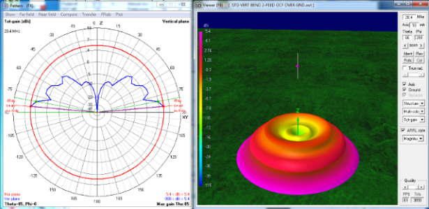
Figure 6 at 2WL
The strongest radiation lobe of a standard vertical dipole at 3 wavelengths elevation is the
same maximum beam as 2 wavelengths. The changes due to increasing height are now the
increasing number of "lobes" or rings from the reflected ground waves adding more upward radiation.
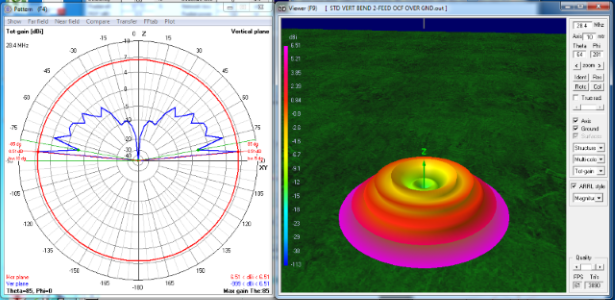
Figure 7 at 3WL
The radiation pattern of a standard vertical dipole at 1/2 wavelength shows elevation aimed lower...
at 15° from horizontal but with an even wider beam width of 40° due to the first ground wave.

Figure 4 at 1/2WL
The strongest radiation lobe of a standard vertical dipole at 1 wavelength elevation is aimed 10° from horizontal with a much narrower beam width of 25°. There are now two ground waves apparent.

Figure 5 at 1WL
The strongest radiation lobe of a standard vertical dipole at 2 wavelengths elevation has the maximum beam aimed at 5° up from horizontal with an extremely narrow width of only 5°.
There are two reflected ground waves added for each wavelength increase in elevation. These are refered to as "lobes" in the polar cross-section plots. However the reality is they are added rings in the far field radiation pattern as seen in the color 3D views.

Figure 6 at 2WL
The strongest radiation lobe of a standard vertical dipole at 3 wavelengths elevation is the
same maximum beam as 2 wavelengths. The changes due to increasing height are now the
increasing number of "lobes" or rings from the reflected ground waves adding more upward radiation.

Figure 7 at 3WL
Dick Reid, KK4OBI at QSL.net

