
Navigation
Menu
Center-fed Bent-Dipoles
Horizontal Lateral
Vertical
- OCF
Slow-Wave
Other Topics
Home
Any length of wire has a resonant frequency. Think of a guitar string. If you touch it in the middle you now have two halves at twice the frequency. Touch at one-third you get three sections at three times the resonant frequency. At one-fourth, get four sections at four times the resonant frequency, et cetera. These are harmonics.
Starting with a wire that resonates at 80 meters (3.5 mHz), the second harmonic is two halves at 40 meters (7 mHz); third harmonic is three parts at 30 meters (10.5 mHz); 4th is four parts 80/4=20 meters (14 mHz). 5th = 17 meters (17.5 mHz). 6th = 15 m (21 mHz). 7th =12m (24.5 mHz). 8th = 10m (28 mHz).
Antenna modeling shows that a resonant half wave wire can be fed at any point (End, Off-Center, Center) without changing gain or efficiency... only impedance. Away from center, impedance is high so a transformer is used to match an antenna to coaxial cable. At 8% from the end is the unique feedpoint where harmonics number 2 to 8 fall into best alignment. At this point the Standard Deviation between those seven resonant length's is only 0.3 meters. These can be aligned with the 1st harmonic by using a small inductance and capacitance.
What
Happens
If...
You Transmit on Harmonics of a
Inverted-V EFHW Antenna?
You Transmit on Harmonics of a
Inverted-V EFHW Antenna?
 To answer the question, a wire antenna model was
developed*
based on data reported by Danny Horvat, N4EXA and E73m (MyAntennas.com), a
model by VE3KL and the
spherical geometry technique used for the Bent Dipoles "Elevated
Radials"
study.
To answer the question, a wire antenna model was
developed*
based on data reported by Danny Horvat, N4EXA and E73m (MyAntennas.com), a
model by VE3KL and the
spherical geometry technique used for the Bent Dipoles "Elevated
Radials"
study.4NEC2 Antenna Model: Here
The pattern of antenna radiation is dependant on Wavelength Height, the distance in wavelengths above the ground. The general rule is to position an antenna is "as high as wide". This halfwave elevation provides the maximum signal to the sides with minimum signal skyward. No feedline is considered.
Click here to see a table of the elevation effects on antenna radiation pattern for these bands: 160m, 75/80m, 40m, 20m, 15m, 10m and 6m
Note: Every half-Wavelength Height adds a figure-8 broadside to any half-wavelength of wire. A round reflection dome develops between each half-wavelength.
As seen from the table, an 80 meter antenna at half-Wavelength Height should be at 129.5 feet. This is impossible for most amateur radio operators, therefore the modeling data that follows is based on a 12.2 meter elevation (40 feet). This is a practical maximum for commercial masts, telescoping poles and trees.
If you must mount an antenna lower, remember that the closer the to ground: (1) the more signal absorbed by the ground; (2) the remaining signal is increasingly reflected skyward. (You can use the above 4NEC2 antenna model to see what happens at specific elevations and bands).
Model Data by Harmonic
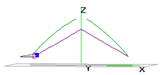
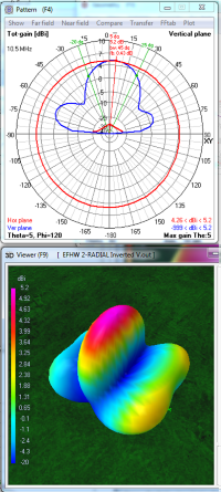
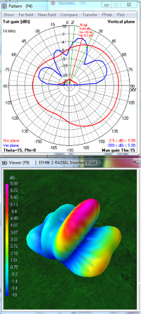
The following data are for the far field radiation patterns and 3D color views of an End Fed Half Wave Inverted-V antenna with the high point in the center at 40 feet and the ends about 10 feet over ground.. The included angle between the arms is 120°.
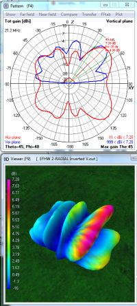
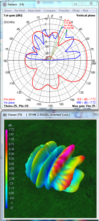
The direction of radiation is the Blue trace on the polar graphs. Horizontal is 90°. Up is 0°.
On the 3D views the Red color indicates the stronger radiation.
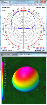
| 80m
Fundamental 1 lobe 3.16 dBi at 0° |
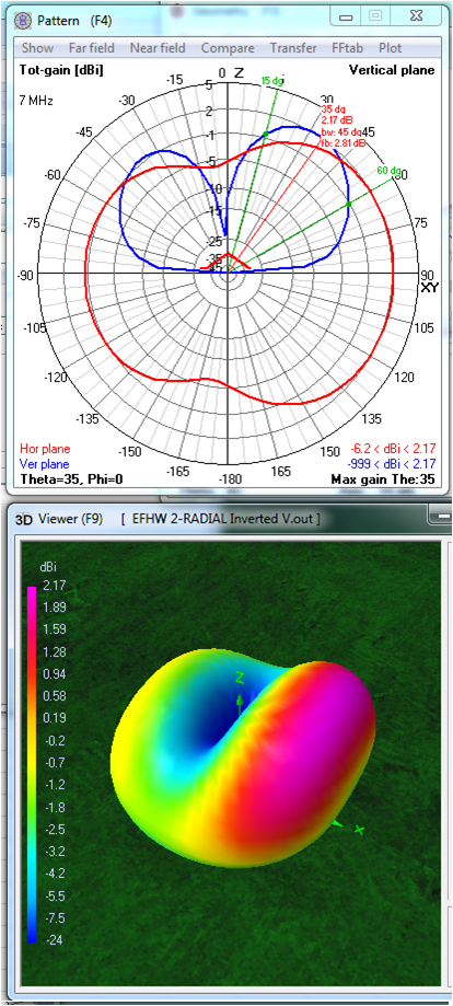
40m
2nd Harmonic 2 lobes 2.17 dBi at 35° |
30m
3rd Harmonic 3 lobes 5.2 dBi at 5° |
 |
 |
 |
On 80 meters, most of the wire is a fraction of a half-Wavelength Elevation high. Compared to a straight wire at 40 feet, about half of the signal is lost into the ground in the V form, from 6.06 dBi, down to 3.16 dBi. The remaining signal is reflected straight up in an almost perfect circle. This works well for NVIS communications with nearby stations.
Interestingly, the vertically polarized radiation is a figure-8 aligned with the arms of the V. The horizontal portion is a figure-8 broadside. At 15° above the horizon for distance communication, the radiation pattern is a very weak figure eight (around -6 to -7 dBi) from each end with nulls broadside.
 On 40 meters,
each half of
the wire is resonating independently to
produce two current lobes, one for each half-wave. The
model shows the half wave away from the feed point is favored*.
However, about 2/3 of the total inverted-V signal is lost to
ground when compared to a straight EFHW wire at 40 feet; from 6.12 dBi
down to 2.13 dBi (which equals 0.0 dBd or zero gain).
On 40 meters,
each half of
the wire is resonating independently to
produce two current lobes, one for each half-wave. The
model shows the half wave away from the feed point is favored*.
However, about 2/3 of the total inverted-V signal is lost to
ground when compared to a straight EFHW wire at 40 feet; from 6.12 dBi
down to 2.13 dBi (which equals 0.0 dBd or zero gain).Most of the radiation is horizontally polarized and divides like a 4-leaf clover with each leaf being diagonal to the line of the wire. Blended with this is the vertically polarized component rising at a high angle. This vertical component fills in between the horizonal lobes to produce the broad end-radiation seen in the 40M 3D picture above. Because part of the wire is over a quarter wavelength high the radiation pattern begins to be slightly directional broadside (fatter).
At 15° take-off-angle for distance communications, the radiation strength is very weak, down to -5 dBi off the ends but one S-unit stronger (-2 dBi) broadside due to elevation gain.
 On 30 meters, the wire is
now resonating in three half-waves. The middle halfwave being highest is strongest and radiates the 5.2 dBi
maximum gain upward.
The lower half-wave sections on each end have weaker radiation but with a useful take-off-angle of 25° and up to 3 dBi gain.
On 30 meters, the wire is
now resonating in three half-waves. The middle halfwave being highest is strongest and radiates the 5.2 dBi
maximum gain upward.
The lower half-wave sections on each end have weaker radiation but with a useful take-off-angle of 25° and up to 3 dBi gain. | 20
m 4th Harmonic 4.lobes 5.99 dBi at 15° |
15m
6th Harmonic 6 lobes 7.28 dBi at 45° |
10m
8th Harmonic 8 lobes 7.72 dBi at 25° |
 |
 |
 |
 On 20 meters,the
wire divides into four half-wave resonating sections... two on each side. Each
half-wave is
made up of a horizontal figure-8 with vertically polarized radiation
filling in to make the long patterns seen in the 20 meter 3D picture
above. The model shows an
offset favoring the 5.96 dBi red-top lobe.* The moe useful lobe on the right has a 30°
Take-Off-Angle has 4 dBi gain at 30° off the corners and 3 dBi
from the middle.
On 20 meters,the
wire divides into four half-wave resonating sections... two on each side. Each
half-wave is
made up of a horizontal figure-8 with vertically polarized radiation
filling in to make the long patterns seen in the 20 meter 3D picture
above. The model shows an
offset favoring the 5.96 dBi red-top lobe.* The moe useful lobe on the right has a 30°
Take-Off-Angle has 4 dBi gain at 30° off the corners and 3 dBi
from the middle.The two half-wave sections near the top of the V are directional (wide) because they are centered on a half-Wavelength Height. Never-the-less the overall pattern is stronger in-line with the wire because of the vertically polarized components in the radiation pattern.
 On 15 meters,
the wire has six resonant half-wave sections; three on each arm of the V. Each half-wave is
made up of a horizontal figure-8 with vertically polarized radiation
filling in to make the six long patterns seen in the 15 meter 3D picture
above.
On 15 meters,
the wire has six resonant half-wave sections; three on each arm of the V. Each half-wave is
made up of a horizontal figure-8 with vertically polarized radiation
filling in to make the six long patterns seen in the 15 meter 3D picture
above. Because the half-wave near the peak of the V is between two half waves, ground reflection causes a vertical dome typified by the the green-top lobe. The red-top lobe is from the middle half-wave which is centered at a half-Wavelength Height. It is stronger with about 7 dBi both broadside and at a 45° up angle. Generally the direction in line with the wire and away from the feed point is favored.* The lowest lobes are around 1 dBi at 10 to 15° Take-Off-Angle which favors DX.
 On 10 meters, the wire resonates in
eight resonant half-wave sections, four on each arm of the V. Each of these half-waves is
made up of a horizontal figure-8 with vertically polarized radiation
filling in to make the eight long patterns seen in the 10 meter 3D picture
above.
On 10 meters, the wire resonates in
eight resonant half-wave sections, four on each arm of the V. Each of these half-waves is
made up of a horizontal figure-8 with vertically polarized radiation
filling in to make the eight long patterns seen in the 10 meter 3D picture
above.The middle two half-wave sections are strong because they are around a half-Wavelength Height.
The strongest (third from right) is 7.72 dBi but aimed 25° from vertical. The red-tinged lobe (second from right) is about 5 dBi at 45°. For distance communications the lowest lobes are around 4 dBi at 10 to 15° Take-Off-Angle. With these large number of resonant half-waves, the inverted-V at 10 meters is not particularly directional.
Placement of the V bend point should be done with consideration of the half-waves on each arm.
The patterns for 17 meters and 12 meters are not included to simplify visualiation.
All 3D views are from the same angle and compass heading.
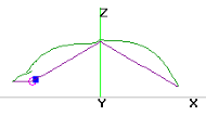
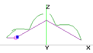
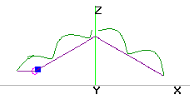
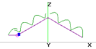
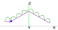
* Note: In the antenna current diagram (top) there is a simulated counterpoise and small inductance (blue square) at the feedpoint (purple circle). Presumably this causes the model's predicted signal to be slightly stronger at the opposite end.