
Navigation
Menu
Center-fed Bent-Dipoles
Horizontal Lateral
Vertical
- OCF
Slow-Wave
Other Topics
Home
 The
conventional ways of putting up a dipole in limited space involve
bending the ends or bending the antenna at the feed-point into an L or
V
configuration. However, since the cell phone began, there has
been a period of ongoing development in reducing the size of antennas
from telescoping antenna, to rubber duck, to stubs, to
no external antenna at all.
The
conventional ways of putting up a dipole in limited space involve
bending the ends or bending the antenna at the feed-point into an L or
V
configuration. However, since the cell phone began, there has
been a period of ongoing development in reducing the size of antennas
from telescoping antenna, to rubber duck, to stubs, to
no external antenna at all. Built-in antennas take various forms from tiny dipoles to meander, zig-zag and fractal shapes as well as inverted L, F and slot types etched into circuit boards. Besides cell phones, these miniature antennas will also be found in multi-band UHF routers, the theft protection Radio Frequency IDentification (RFID) tags in merchandise, wireless automotive door locks and ignition, GPS units, Wi-Fi in laptops, iPads, printers, TouchTablets, etc.. Just think how much faster you could drive through RFID automated toll booths as the antenna technology developed.
The frequencies run typically up to 5 gHz. Never-the-less the principles involved apply to HF and VHF amateur bands. Exploring these principles is where wire antenna computer modeling comes in.
What Happens If...
a Dipole is Bent into a Zig-Zag?
a Dipole is Bent into a Zig-Zag?
In the early day of antenna miniaturization, research papers examined the Zig-Zag method. Commonly the studies used fixed wire lengths or fixed angles, typically, 90°, 60° and 45°, which it turns out, will not match 50 ohm coax very well.
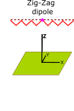
The study done here does not fix angles. Instead, the Length is set as a ratio of Zig-Zag half-wave dipole and divided into the desired number of Segments per side, (4,5,6,7,8). The antenna model program finds the perfect Zig-Zag Height . Figure 1.
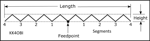
Figure 1
The starting Length is calculated as a Ratio (0.9, 0.8, etc.) of the length of a theoretical straight dipole, 150/MHz = meters. By using the optimization function, the antenna model program iteratively converges on the Height that gives the best match for the target frequency. This study proceeds stepwise form 0.9 to 0.5 ratio to determine the characteristics for the various Zig-Zag dipoles of interest.
4NEC2 Antenna Models here: 8 Zig-Zag, 10 Zig-Zag, 12 Zig-Zag, 14 Zig-Zag, 16 Zig-Zag
A straight dipole has an impedance somewhere around 70 ohms when the lowest SWR is achieved. If you change it by bending, impedance goes down and the resonant frequency goes up. Resonance is achieved by adjusting the length.
A Zig-Zag dipole is different. If you compress it to change the Length, impedance still goes down but the resonant frequency stays the same by adjusting the Height.
Accordingly, a 50 ohm match can be found for whatever the number of Zig-Zags in a dipole.
In this study, each antenna passed through a point where the results gave a SWR of 1.00 to 1.01 with a reactance less than +/- 0.2 j. Reflection coefficients exceed -50 dB. Maximum radiation angle is at 25°-30° up from horizontal. Beam width at 3 dB down from maximum is 30°. Zig-Zagging gives almost the same far field radiation pattern as a straight dipole.
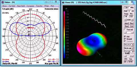
Figure 2
The performance characteristics of each of the five Zig-Zag dipoles studied were virtually the same: The curious exception is the slightly plump 12 Zig-Zag dipole pattern where Gain is 6.2 to 6.5 dBi and Efficiency is 63% to 65%. Otherwise:
- Gain: 7.1 to 7.2 dBi. (About 0.2 dBi less than a straight dipole).
- End Nulls: -2.4 to -4.4 dBi. (About 0.3 dBi less than a straight dipole).
- Radiation Efficiency: 72-75%. (About 2% less than a straight dipole).
How
much shorter is a
dipole if it is bent into a Zig-Zag form?
It turns out that with more Zig-Zags, resonant length stays the same (80%) ... surprisingly, with virtually no compromise in performance. As predicted by computer model, they work equally well .
Here
are the 4,5,6,7 and 8 ZigZags per arm comparing only one side of a
half-wave dipole.
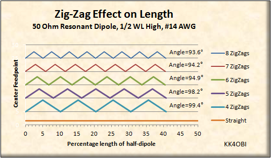
Figure 3
Relative length according to number of ZigZags
In Figure 3, The bend Angles shown are calculated from Height and Width of a ZigZag.
The lengths are in percentage of a half-wavelength = 150/MHz in meters.
For
example at 52 MHz: 150/52 = 2.8846 meters length for frequency
of interest.
Sample
calculations using the 4
Zig-Zags per side data in Table 1 below:
2.8846*0.8 = 2.38
meters Length of a dipole with 4 Zig-Zags per side.2.8846*0.0451 = 0.13 meters Height of Zig-Zags.
2.8846*0.09 = 0.26 meters Width of each Zig-Zag.
2.8846*1.0193= 2.94 meters Length of wire needed to make the 8 Zig-Zag dipole.
The example data-set was verified to be accurate by running the values in an antenna model.
| Zig-Zags per side | Length % of dipole |
Height % of Zig-Zags |
Width % of Zig-Zags |
Length % Total Wire Needed |
| 4 | 80 |
4.51 |
9.0 |
101.93 |
| 5 | 80 | 3.72 |
7.2 |
103.51 |
| 6 | 80 | 3.16 |
6.0 |
87.14 |
| 7 | 80 | 2.79 |
5.14 |
75.92 |
| 8 | 80 | 2.50 |
4.5 |
67.23 |
Table 1
Characteristics
Because a Zig-Zag dipole can be resonant at whatever length desired, only the impedance is the limiting factor.
In Figure 4 below can be seen how the impedance (Red line) falls from around 70 Ohms, to 50 Ohms at 0.8 ratio, to around 20 Ohms at 0.5 ratio (half-length). Looking at the Blue line (SWR) it is clear that no tuner is needed until a Zig-Zag dipole approaches half the length. The slight decline in % Radiation Efficiency (Green line) is inconsequential.
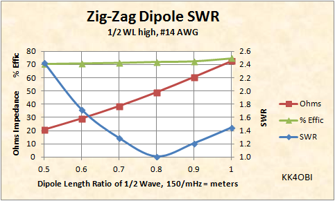
Figure 4
The antenna model is based on accordian-like compressing of a specific number of Zig-Zags to be a specific length, the height of the Zig-Zags is the controling dimension.
In Figure 5 below can be seen how the Height (Green line) of the peaks increase as the length of the dipole is compressed (0.9, 0.8, etc.). Note also that Gain (Red line) declines slightly as the dipole gets shorter; to about a half-dB at half-length.
..

Figure 5
We need one more dimension.
It is necessary to find the length of wire that, when bent, will resonate on the target frequency. Up to this point only the lengths for 52 MHz were given in the example above.
Unfortunately for the accordian technique, this necessary dimension cannot be determined by the antenna modeling software. It requires using the Pythagorean theorem to find the length of the side (hypotenuse) of the Zig. (The base dimension of the right triangle is the half the width of a Zig-Zag. The side adjacent is the height of the Zig. See models for equations). The length of wire needed is determined by adding up the number of sides in the antenna. For the 8 Zig-Zag dipole shown at the top of the page, you will count 16 sides.
In Table 2 below are the ratios to find the % Wire Length that, when Zig-Zagged, will resonate near the target frequency. Intermediate values are determined by interpolation. Correction for Velocity Factor should be considered. Tuning can be adjusted by stretching to lower frequency or compressing to raise frequency. Note that more Zig-Zags use less wire.
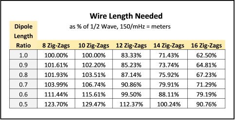
Table 2
Once a Zig-Zag dipole is compressed to less than 0.7 ratio (70% long), the impedance will be low and the rise in SWR may be something you might want to deal with.
For this, look to the side menu. Under "OCF" select: "OCF Impedance". There, Figure 1 gives the Effect of Off-Center Feed as a means of raising impedance. This technique works similarly for Zig-Zag antennas by moving the feedpoint to different Zig. Be aware that using extremes in compression and OCF will cause a slight skewing of the radiation pattern. A choke balun is advised to supress common mode problems.
Summary
The modeling results of the "slow-wave" technique of Zig-Zagging a dipole turn out to be particularly interesting. The thing that jumps out is that Zig-Zags have practically no effect on dipole performance. The second big plus is how tolerant is the tuning. Practically any combination can be used to shorten a dipole up to 40% without the need of a tuner.
On the other hand, where most anyone can string up straight wires, building a Zig-Zag dipole is best left to the more creative hams.
Dick Reid, KK4OBI at qsl.net