
Navigation
Menu
Center-fed Bent-Dipoles
Horizontal Lateral
Vertical
- OCF
Slow-Wave
Other Topics
Home
Any length of wire has a resonant frequency. Think of a guitar string. If you touch it in the middle you now have two halves at twice the frequency. Touch at one-third you get three sections at three times the resonant frequency. At one-fourth, get four sections at four times the resonant frequency, et cetera. These are harmonics.
Starting with a wire that resonates at 80 meters (3.5 mHz), the second harmonic is two halves at 40 meters (7 mHz); third harmonic is three parts at 30 meters (10.5 mHz); 4th is four parts 80/4=20 meters (14 mHz). 5th = 17 meters (17.5 mHz). 6th = 15 m (21 mHz). 7th =12m (24.5 mHz). 8th = 10m (28 mHz).
Antenna modeling shows that a resonant half wave wire can be fed at any point (End, Off-Center, Center) without changing gain or efficiency... only impedance. Away from center, impedance is high so a transformer is used to match an antenna to coaxial cable. At 8% from the end is the unique feedpoint where harmonics number 2 to 8 fall into best alignment. At this point the Standard Deviation between those seven resonant length's is only 0.3 meters. These can be aligned with the 1st harmonic by using a small inductance and capacitance.
The key characteristic that does change is the radiation pattern on each harmonic.
What
Happens
If...
You Transmit on Harmonics of a
Sloping EFHW Antenna?
You Transmit on Harmonics of a
Sloping EFHW Antenna?
 To
answer the question, a wire antenna model was
developed*
based on data reported by Danny Horvat, NE4XA and E73m (MyAntennas.com), a
model by VE3KL and the
spherical geometry technique used for the Bent Dipoles "Elevated
Radials"
study.
To
answer the question, a wire antenna model was
developed*
based on data reported by Danny Horvat, NE4XA and E73m (MyAntennas.com), a
model by VE3KL and the
spherical geometry technique used for the Bent Dipoles "Elevated
Radials"
study.4NEC2 Antenna Model: Here
The pattern of antenna radiation is dependant on Wavelength Height, the distance in wavelengths above the ground. The general rule is to position an antenna is "as high as wide". This halfwave elevation provides the maximum signal to the sides with minimum signal skyward. No feedline is considered.
Click here to see a table of the elevation effects on antenna radiation pattern for these bands: 160m, 75/80m, 40m, 20m, 15m, 10m and 6m
Note: Every half-Wavelength Height adds a figure-8 broadside to any half-wavelength of wire. A round reflection dome develops between each half-wavelength.
As seen from the table, an 80 meter antenna at half-Wavelength Height should be at 129.5 feet. This is impossible for most amateur radio operators, therefore the modeling data that follows is based on a 12.2 meter elevation (40 feet). This is a practical maximum for commercial masts, telescoping poles and trees.
If you must mount an antenna lower, remember that the closer the to ground: (1) the more signal absorbed by the ground; (2) the remaining signal is increasingly reflected skyward. (You can use the above 4NEC2 antenna model to see what happens at specific elevations and bands).
Model Data by Harmonic
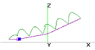
The following data are for the far field radiation patterns and 3D color views of a sloping End Fed Half Wave antenna with the feed point near ground and curving upward to 40 feet at the far end.
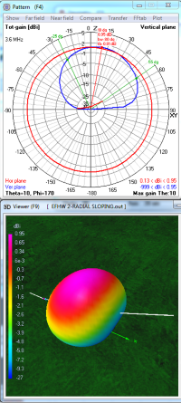
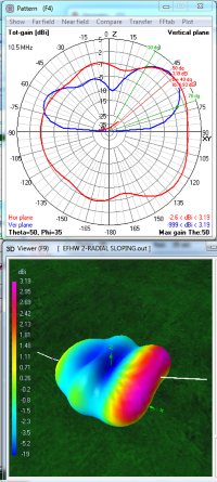
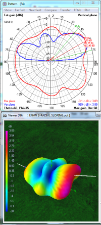
The direction of radiation is the Blue trace on the polar graphs. Horizontal is 90°. Up is 0°.
Red color indicates the stronger radiation on the 3D views.
| 80m
Fundamental 1 lobe 0.95 dBi at 10° |
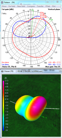
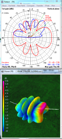
40m
2nd Harmonic 2 lobes 2.13 dBi at 26° |
30m
3rd Harmonic 3 lobes 3.19 dBi at 50° |
 |
 |
 |
On 80 meters, with the end of the antenna close to the ground, a six-fold loss in gain stands out... 6.06 dBi at 40 feet horizontal drops to 0.95 dBi when sloped. Most of the antenna's elevation is only a small fraction of a half-Wavelngth Height so only a slight directional elongation develops. Because of the slope, the oval vertical radiation dome is tilted 10° away from vertical.
The horizontally polarized portion of the radiation is broadside. This signal at a low angle for distance communication is very weak; in the range of -5 to -15 dBi.. The vertically polarized portion, unsuprisingly, is strong and primarily from part of the dipole nearest the ground. The antenna is most suitable for short range NVIS contacts.
 On 40 meters the antenna
radiates as two half-waves. Gain drops by 2/3 from 6.12 dBi at 40 feet
down to 2.13 dBi when sloping (Signal points up at 25° away from
vertical). The lower half-wave section drops to 0.0 dbi gain at (at 55° away from
vertical). Each half-wave is composed of a horizontal figure-8 broadside to the wire with a single vertically
polarized lobe in between to form the two wide lobes seen in the 40 meter 3D
view above.
On 40 meters the antenna
radiates as two half-waves. Gain drops by 2/3 from 6.12 dBi at 40 feet
down to 2.13 dBi when sloping (Signal points up at 25° away from
vertical). The lower half-wave section drops to 0.0 dbi gain at (at 55° away from
vertical). Each half-wave is composed of a horizontal figure-8 broadside to the wire with a single vertically
polarized lobe in between to form the two wide lobes seen in the 40 meter 3D
view above.Most of the antenna is less than 1/3 Wavelength Height so ground reflection is dominant and broadside gain is small. The vertically polarized portion aligns with the wire. This provides low angle signal for distance comunication of around -2 dBi from the low end of the antenna and -11 dBi from the high end. Oddly, the chances for making contacts are better toward the low end of the antenna.
 On 30 meters, the antenna
radiates as three half-waves. The one-third farthest from the
ground (to right) is the strongest. Its gain drops from 7.37 dBi
at 40 feet to 3.19 dBi when sloped (pointing 50° away from vertical).
The middle third drops to -5 dBi. The lowest third drops to 0.0
dBi. Each one-third is composed of two horizontally polarized
lobes on each
side of the wire with a vertically polarized lobes in between to
form the three wide lobes seen in the 30 meter 3D view above.
On 30 meters, the antenna
radiates as three half-waves. The one-third farthest from the
ground (to right) is the strongest. Its gain drops from 7.37 dBi
at 40 feet to 3.19 dBi when sloped (pointing 50° away from vertical).
The middle third drops to -5 dBi. The lowest third drops to 0.0
dBi. Each one-third is composed of two horizontally polarized
lobes on each
side of the wire with a vertically polarized lobes in between to
form the three wide lobes seen in the 30 meter 3D view above.All of the antenna is less than the half-Wavelength Height of 46 feet so broadside gain is just beginning to appear. Ground reflection is still considerable. Low angle signal for distance comunication is around 0.8 dBi from the low end but only -7 dBi from the high end. The chances for making contacts are better toward the low end of a sloping antenna.
| 20
m 4th Harmonic 3.lobes 3.89 dBi at 60° |
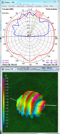
15m
6th Harmonic 6 lobes 5.56 dBi at 40° |
10m
8th Harmonic 8 lobes 4.62 dBi at 20° |
 |
 |
 |
 On 20 meters,
the antenna
radiation divides into four half-wave segments. Each segment is
composed of
a horizontally polarized figure-8 lobe. Vertically polarized radiation
aligns with the wire and is strong at the ends. This creates the long shapes
seen in the 20 meter 3D view above. In this model the two middle
segments merge.
On 20 meters,
the antenna
radiation divides into four half-wave segments. Each segment is
composed of
a horizontally polarized figure-8 lobe. Vertically polarized radiation
aligns with the wire and is strong at the ends. This creates the long shapes
seen in the 20 meter 3D view above. In this model the two middle
segments merge.Maximum signal of 3.89 dBi comes from the highest radiating segment which is around a half-Wavelength high (33 feet). The lobes from this segment are pointing +/- 35° to the side of the wire to give broad coverage. The vertically polarized lobe at this end strongly bridges the horizontal lobes to provide particularly wide coverage in this direction.. At the low end of the slope there is about 1.5 dBi gain at a 20° Take-Off-Angle. Gain is slightly lower to the sides of the sloping wire.
 On 15 meters, the antenna
radiates as six half-waves. Each one-sixth is composed of a
horizontally polarized figure-8 on each
side of the wire with a single vertically polarized lobe filling in between. In this model the two highest segments merge.
On 15 meters, the antenna
radiates as six half-waves. Each one-sixth is composed of a
horizontally polarized figure-8 on each
side of the wire with a single vertically polarized lobe filling in between. In this model the two highest segments merge.The beginning of a second horizontal ring of lobes is seen as the antenna is approaching a two-Halfwave Elevation (44 feet). However, being between two halfwaves, there is still some ground reflection dome remaining. Maximum signal 5.56 dBi at the high end of the slope is 50° from vertical. Fortunately there is around 3 dBi low angle radiation from side lobes and the low end of the slope. Radiation is generally high angle with many peaks and nulls.
 On 10 meters,
the antenna radiates as eight half-waves. Each one-eighth is composed
of a horizontal figure-8 with a single vertically polarized lobe in
between.
The increasingly complex radiation is generally of high angle with many
peaks and nulls. In this model the two highest and lowest segments
merge.
On 10 meters,
the antenna radiates as eight half-waves. Each one-eighth is composed
of a horizontal figure-8 with a single vertically polarized lobe in
between.
The increasingly complex radiation is generally of high angle with many
peaks and nulls. In this model the two highest and lowest segments
merge.A second layer of horizontal lobes is seen in the 10 meter 3D picture above because the antenna height excedes the 32 foot two-Wavelenght Height. The high dome seen is a characteristic of any antenna with its effective elevation is between two half-waves. This directs the maximum gain of 4.62 dBi at a very high angle of 20°. The overall radiation pattern is generally omni-directional.
The patterns for 17 meters and 12 meters are not included to simplify visualiation.
All 3D views are from the same angle and compass heading.
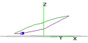
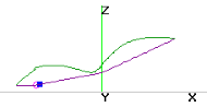
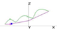
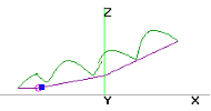
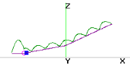
* Note: In the antenna current diagram (top) there is a simulated counterpoise and small inductance (blue square) at the feedpoint (purple circle). Presumably this causes the model's predicted signal to be slightly stronger at the opposite end.