
Navigation
Menu
Center-fed Bent-Dipoles
Horizontal Lateral
Vertical
- OCF
Slow-Wave
Other Topics
Home
Bending
a dipole most usually is considered because of space limits but also as
a means of tuning. When bending up and down the effects
of ground come into play depending on which arm is higher or lower.
Bending to the side is a simpler process because the arms of the dipole
stay the same distance above ground. With this constraint answering the
"What happen if..? question is where computer wire antenna modeling
shines.
 What Happens
If...
What Happens
If...
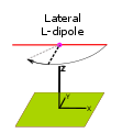
You Bend a Dipole Laterally
into an "L"?
In this study the model is programmed to treat one arm of a horizontal dipole as fixed and the other arm as variable side-to-side. Standard conditions are: feed point at 1/2 wavelength over average ground and using #14 AWG for the antenna. The software finds the optimized conditions for SWR 50 and minimal reactance at each angle. The study progesses in 15° steps past 90° to an extreme of 135° where the SWR exceeds 3:1.
4NEC2 Antenna Model: Here
Figure 1 below sumarizes the effects on Gain, SWR and % change in resonant Length related to the angle of a lateral L-bend.
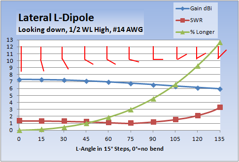
Figure 1
A graphic indication of the L-bend is shown in red.
What Happens
If...You Bend a Dipole Laterally
into an "L"?
In this study the model is programmed to treat one arm of a horizontal dipole as fixed and the other arm as variable side-to-side. Standard conditions are: feed point at 1/2 wavelength over average ground and using #14 AWG for the antenna. The software finds the optimized conditions for SWR 50 and minimal reactance at each angle. The study progesses in 15° steps past 90° to an extreme of 135° where the SWR exceeds 3:1.
4NEC2 Antenna Model: Here
Figure 1 below sumarizes the effects on Gain, SWR and % change in resonant Length related to the angle of a lateral L-bend.
Figure 1
A graphic indication of the L-bend is shown in red.
Along
the top of the graph for
each angle of bend there is a red graphic representation (looking
from above) of the bent dipole.
Looking at the Blue line you will notice that the Gain goes down (as always) when a dipole is bent. The change is not significant until around 60° when it drops below 7 dBi. At 105° the Gain is a full dBi lower and the SWR becomes higher than a standard dipole.
The good side of bending a dipole is that the impendance goes down as the bend increases and passes through 50 ohms on the way down. This characteristic can be used as a method to get a better match for 50 Ohm coax. In this study notice that at 75° bend the SWR (Red line) is the lowest where SWR = 1.02. At 90° the SWR rises to 1.22. At 120° the SWR > 2.
As the angle of bend increases the arm needs to be a certain % Longer (Green line) to maintain resonance. At 75° point the arm will be about 3% longer to get the best match for 50 Ohm coax. If space conservation is the reason for bending, 90° is as short as the antenna gets, At 90° the swinging arm needs to be about 4-1/2 % longer for resonance.
A side note: The antenna model use here is based on a fixed arm and a swinging arm that is optimized in length for lowest SWR. At the more extreme bends past 90° the dipole becomes more and more off-center at the feedpoint. There is no noticeable effect in tuning near the center of the dipole, but by around 10% away from center the impedance will begin to rise enough to notice. In this study around 125° would be a practical bend maximum.
Our standard straight dipole radiates at right angles and has a -2.7 dBi null off each end. However, as you bend a dipole you also skew the angle of radiation to be half the angle between the arms of the dipole.
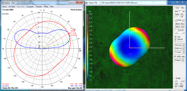
Figure 2 is a example of skew.
The angle included between arms is 90° so the radiation is aimed at 45°...half the angle between arms.
Myth busting
Exactly the opposite for claims about increased gain from "V-Beams" and such:
The ends of the antenna start to contribute gain when a dipole is bent greater than 90°.
Dick Reid, KK4OBI at QSL.net
Looking at the Blue line you will notice that the Gain goes down (as always) when a dipole is bent. The change is not significant until around 60° when it drops below 7 dBi. At 105° the Gain is a full dBi lower and the SWR becomes higher than a standard dipole.
The good side of bending a dipole is that the impendance goes down as the bend increases and passes through 50 ohms on the way down. This characteristic can be used as a method to get a better match for 50 Ohm coax. In this study notice that at 75° bend the SWR (Red line) is the lowest where SWR = 1.02. At 90° the SWR rises to 1.22. At 120° the SWR > 2.
As the angle of bend increases the arm needs to be a certain % Longer (Green line) to maintain resonance. At 75° point the arm will be about 3% longer to get the best match for 50 Ohm coax. If space conservation is the reason for bending, 90° is as short as the antenna gets, At 90° the swinging arm needs to be about 4-1/2 % longer for resonance.
A side note: The antenna model use here is based on a fixed arm and a swinging arm that is optimized in length for lowest SWR. At the more extreme bends past 90° the dipole becomes more and more off-center at the feedpoint. There is no noticeable effect in tuning near the center of the dipole, but by around 10% away from center the impedance will begin to rise enough to notice. In this study around 125° would be a practical bend maximum.
What
happens to the beam direction?...
Skew
Skew
Our standard straight dipole radiates at right angles and has a -2.7 dBi null off each end. However, as you bend a dipole you also skew the angle of radiation to be half the angle between the arms of the dipole.
Figure 2
Figure 2 is a example of skew.
The angle included between arms is 90° so the radiation is aimed at 45°...half the angle between arms.
Myth busting
Exactly the opposite for claims about increased gain from "V-Beams" and such:
- there is no directionality
caused by V-bending
- overall gain goes down
as bend increases. At 105° angle
of bend, gain is down 1 dBi, 13.7%.
The ends of the antenna start to contribute gain when a dipole is bent greater than 90°.
Dick Reid, KK4OBI at QSL.net