
Navigation
Menu
Center-fed Bent-Dipoles
Horizontal Lateral
Vertical
- OCF
Slow-Wave
Other Topics
Home
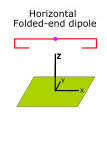
What happens if you fold the ends of a dipole?
Folding is used where a bent dipole needs to be more compact.
For example, if it is found that the ends of a bent dipole touches something or prevents rotation, consider folding. Or, in a Yagi type beam, folded ends would be an interesting possibility to make a smaller antenna. Or, for antennas on 75/80 meters or 40 meters in an attic, having enough height is the eternal problem. Folding may be something to consider.
To study folded dipole configurations, an antenna model was designed based on: 1) a calculated resonant half-wave (velocity corrected), 2) a bend Ratio to define where to bend, 3) the vertical length of the Bend 4) and fine tuning the end of the Fold. The model iteratively converges on the Bend and Fold dimensions that produce the optimal antenna. In this way tuning becomes simple. Just bend and fold the half-wave dipole accordinly and lengthen the tips of the folded ends to find the lowest SWR. (See Figure 1)
To make the results of the studies scaleable to any frequency, the "Ratio" dimensions in the Figures 2, 3 and 4 are fractions of the length of the half-wave dipole.
The antenna model is included. This makes it possible to find the Bend and Fold dimension for any shortened dipole, any size of wire/tubing and/or any elevation over ground.
4NEC2 Antenna Model: Here
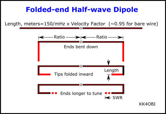
Figure 1
Steps to create a Half-wave Dipole with Folded Ends
The Study
First we find the length of a velocity corrected half-wave dipole at the desired frequency.
Length Meters=150/MHz x Velocity Factor (~0.95 for bare wire).
Using this length the study involves:
1. Seting a Ratio to fix the length of the quarter-wave arms
2) Systematically adjusting the Length of the vertical BEND section
3) Systematically lengthening the FOLD section to find the optimum SWR
As the study progressed it became clear that the bend Ratio of the quarter-wave arms cannot be less than 0.5, that is to say, the dipole cannot be shortened by more than 50%.
The study sumarizes what happens using ratios fixed at 0.5, 0.6, 0.7 and 0.8 (ie. shortened to 50%, 60%,70% and 80% of the length of a half-wave dipole).
Figure 2 below is the SWR vs.Length of bends at these four Ratios of the dipole arms.
For scaling purposes the vr\ertical Length of the downbend is expressed as a ratio of a hslf-wave.
For example, on the Green curve the lowest SWR is around 0.06 Ratio.
Length of the vertical bend at 14.2 MHz: 0.06*150/14.2*0.95=0.6 meters
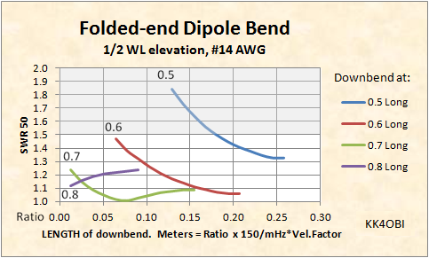
Figure 2
Length of the vertical bend at 14.2 MHz: 0.06*150/14.2*0.95=0.6 meters
Figure 2
With this figure the 0.7 length (Green curve) is favored. At the point where the SWR is lowest, both sides of the fold are about the same length.
As you can see from the SWR curves above, folding a dipole is very forgiving. Just about anything produces a good match for 50 Ohm coax But, if you use the 0.5 curve (Blue line), it is advisable to use Ratio Length > 0.18. In that way the SWR should be under 1.5 at 1/2 wavelength elevation.
Tuning
A straight dipole is the perfect form. Any bend (or sag) has the effect of shortening the radiating body, hence frequency rises, impedance falls. The way this study is designed, the Arms, Bends and Folds add up to the calculated length of the dipole. Only a little length needs be added to the tips of the folds to correct for the shortening effect.
For example, on the Green curve the lowest SWR is around 0.018 Ratio.
At 14.2 MHz: 0.018*150/14.2*0.95=0.06 meters for the length added to the tip of each Fold
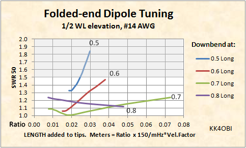
Figure 3
At 14.2 MHz: 0.018*150/14.2*0.95=0.06 meters for the length added to the tip of each Fold
Figure 3
Figure 3 shows what happens to the SWR tuning versus how much length is added to the tips. Again the 0.7 curve stands out. It has the lowest SWR over the broadest range; obviously the easiest to tune. Conversely, the 0.5 and 0.6 curves indicate little posibility for improvement in SWR.
Elevation
A perfect halfwave dipole is also 1/2 wavelength high. That is a tall order for the low bands. What ham can put up a 180 meter antenna at 267 feet? ... or an 80/75 meter antenna at 130 feet? Reality is more like 30 feet for most hams and perhaps 60-80 feet for a few. This means 20 meters for most and 40 meters for a few. Lower than that, performance goes downhill.
Figure 4 below compares what happens to a folded-end dipole that is 0.7 long when it is mounted near ground, that is, less than 0.1 wavelength high.
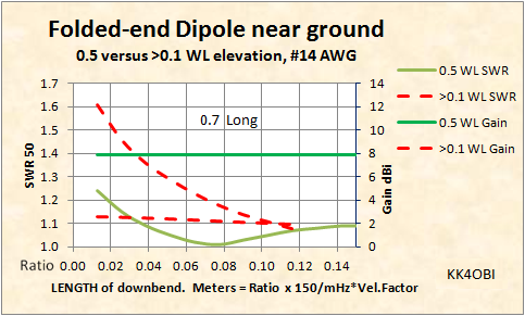
Figure 4
At 0.5 WL high the folded end dipole performs well indeed. The DX radiation pattern is perfectly normal. Gain is remarkedly flat around 8 dBi (Green line). The difference in gain between a straight dipole and a folded end dipole is undetectable, less than 0.2 dB.
At 0.1 WL elevation the same antenna radiates vertically in a perfect circle and exhibits what is politely called "unity gain"... more likely some loss. Low angle DX radiation vanishes and the Green line drops about 6dB to become the horizontal dashed Red line.
Furthermore, at around 0.1 WL the inescapable fact is most of the RF of any horizontal antenna is reflected skyward by the ground. However, some of skyward signal is reflected back down on 160 and 75/80 meters and often on 40 meters. If you live in a valley or have a mountain range in front of you, or participate in ARES or MARS, this Near Vertical Incident Skywave (NVIS) will help.
Notice also the big change on tuning as the downbend segment is longer (larger ratio). The flat Green line becomes a Dashed red curve. This says "no fold". Very near ground a straight bent end gives the better SWR.
In summary, a folded end dipole:
1) Performs like a straight dipole.
2) Is tolerant of how it is folded.
3) Is simple to tune
4) Can be up to 50% shorter
Dick Reid, KK4OBI at qsl.net