AN-SOF Tuning the 10m Free Space Dipole
The previous 10m dipole antenna simulation posting generated a first pass simulation that confirmed the basic dipole design and antenna pattern, but did not look closely at the resultant tuning (VSWR) of the antenna at the selected 28 MHz frequency. This post examines the VSWR parameter and modifies the design to be a better match at 28 MHz.
Starting point: Load the file for the functioning antenna simulation per the previous post. Having completed the Run-All command, select the lower level (not top level) Results tab to see the calculated VSWR of the initial dipole design.
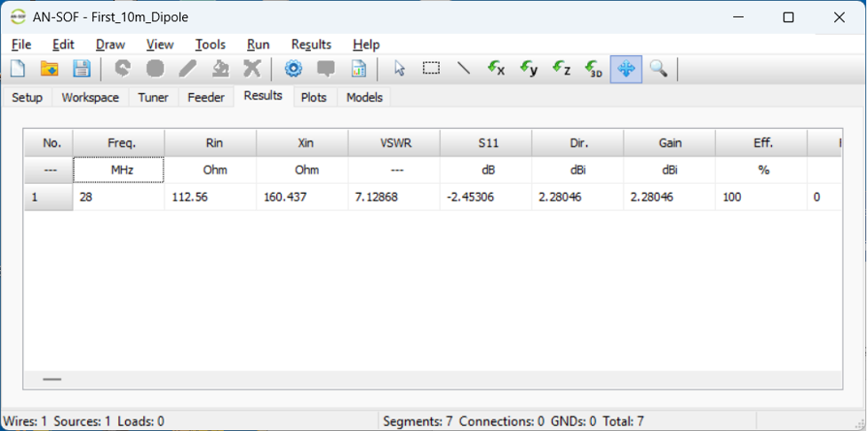
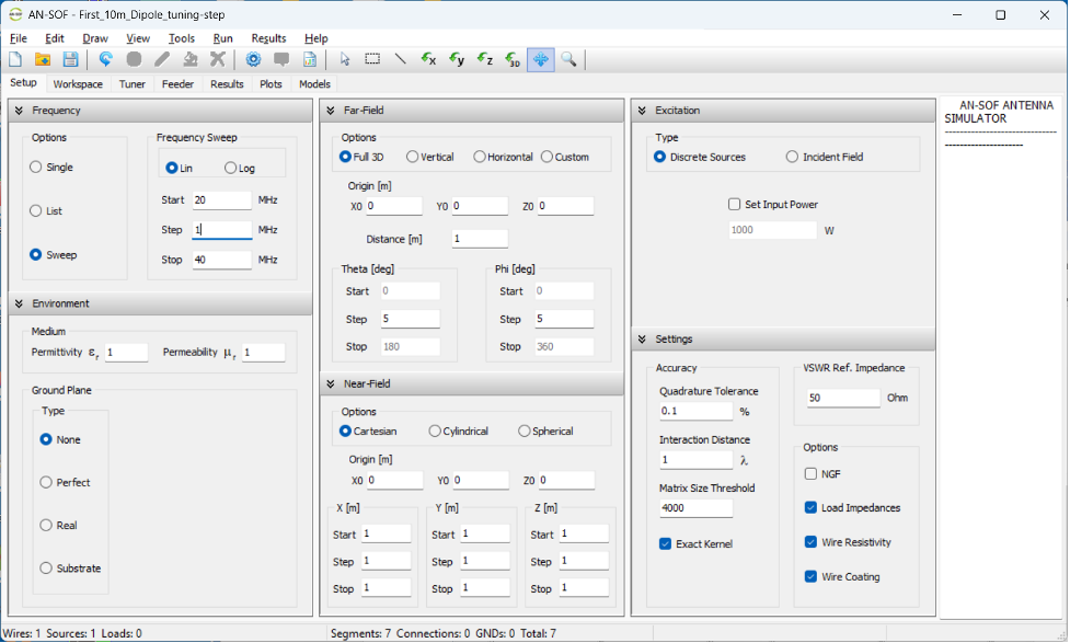
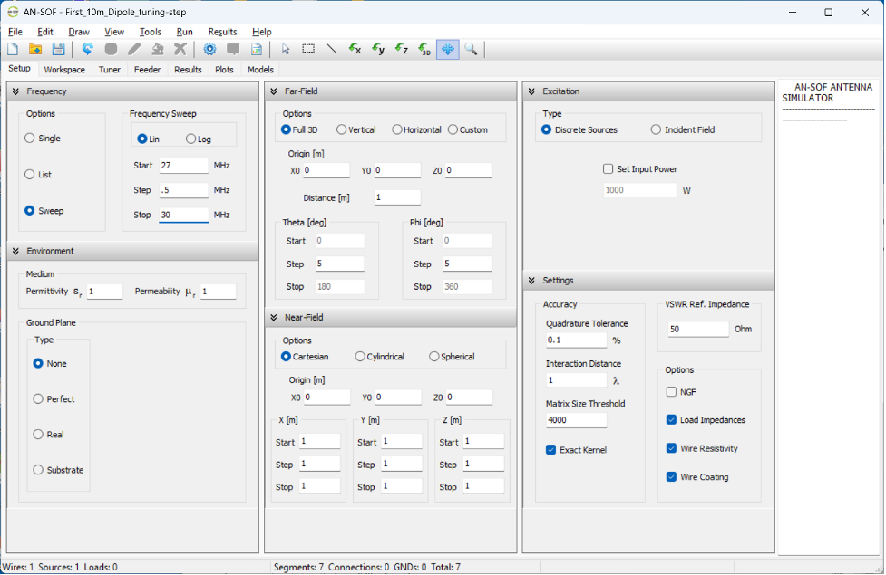
Note that the VSWR is ~7:1 for the 6m dipole length. Let's see if the length is too short, or too long. We'll do this by setting up a frequency sweep for the calculation instead of running it at a single frequency. Save the file with a new name for these tuning updates. With that completed, click on the Setup tab and click the Frequency Sweep radio button. Then set the Frequency Start, Step, and Stop parameters as shown below.
Select Run, Run-All again and then select the lower level Results tab:
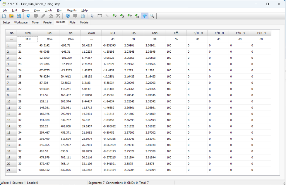
Examine the VSWR column to see that it starts out very high, steadily decreases to a minimum and then increases again as the frequency proceeds to the upper limit. Click on the next tab to the right (Plots) to see how the VSWR varies over frequency.
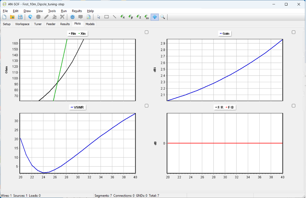
The initial design is resonant closer to 24 MHz than the desired 28 MHz, 10m band. To get closer to 28 MHz and knowing that the length is too long, I used an on-line dipole calculator to determine that a better length is 5.1 meters overall. Return to the workspace tab, right click on the dipole wire, and set the Z1 and Z2 parameters as shown below.
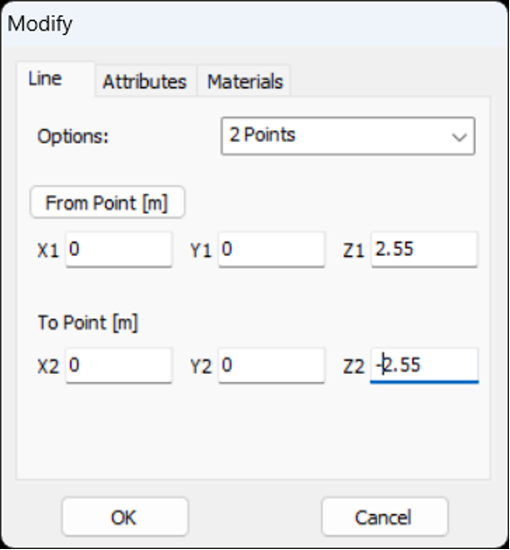
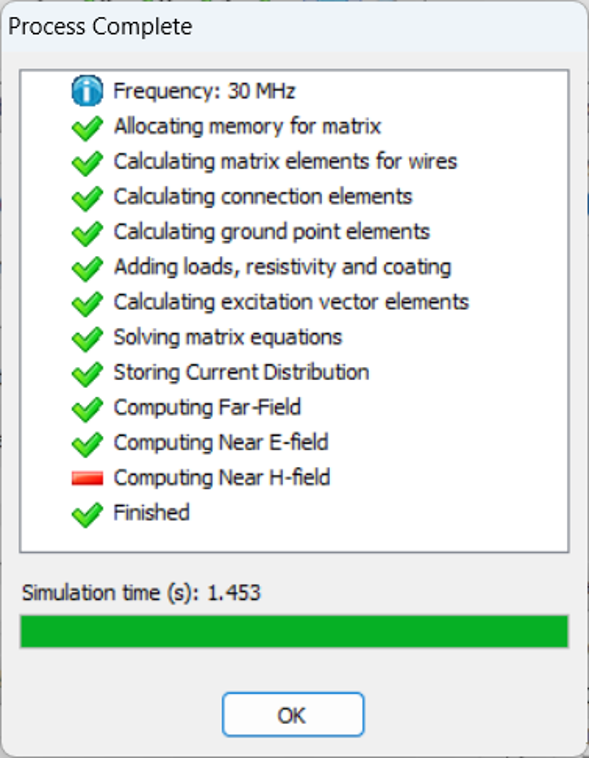
Click OK, and select Run, Run-All from the top level menu.
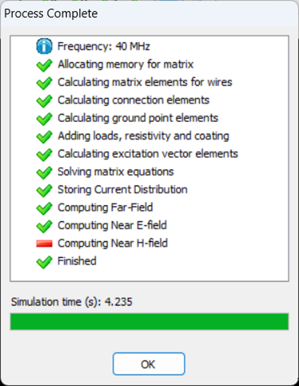
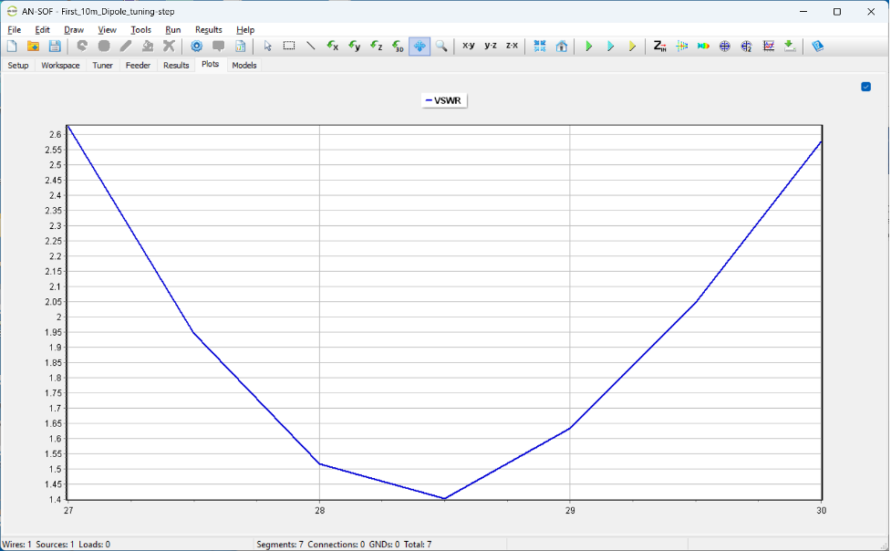
Return to the lower level Plots tab to see how changing the length impacted the resonant frequency.
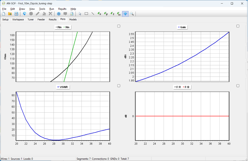
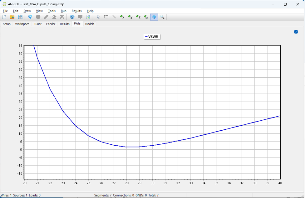
This is much better! Click on the small square to the upper right of the VSWR chart to expand that graph to fill the screen.
Now that we're closer to the ideal length, we can narrow up the frequency span again and see how the VSWR looks across the desired frequency range (27-30 MHz). Select the Setup tab and set the Frequency section parameters as shown below.
Select the top level Run menu and select Run-All.
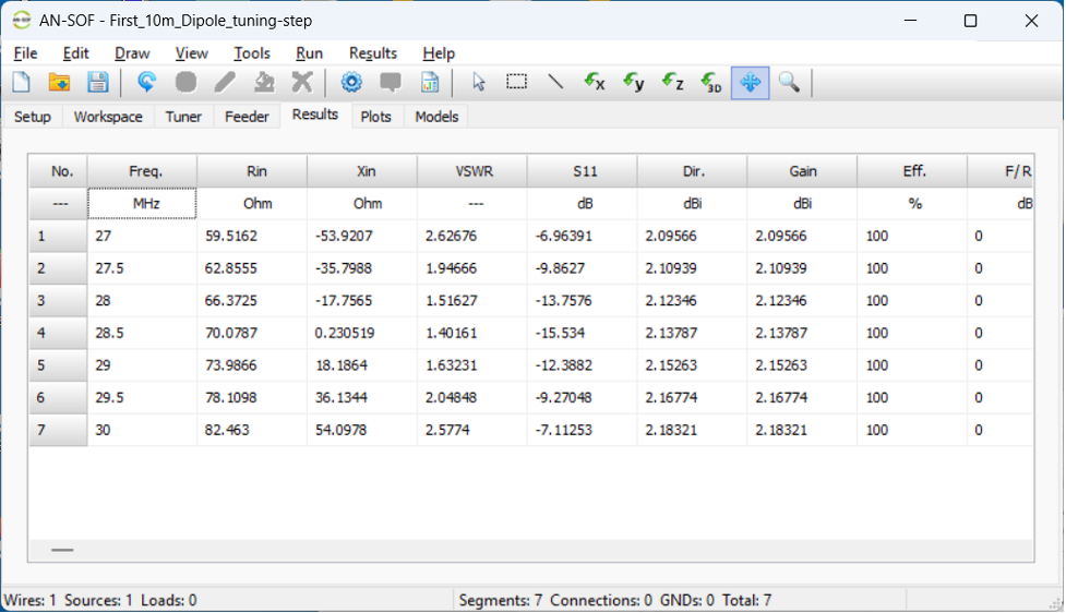
Select the lower tab Results to see how the VSWR varies over the new frequency range.
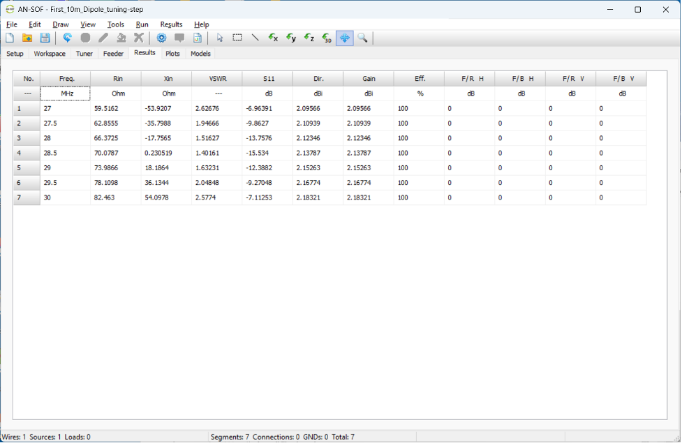
The VSWR is easily under 3:1 with the new shorter length design.
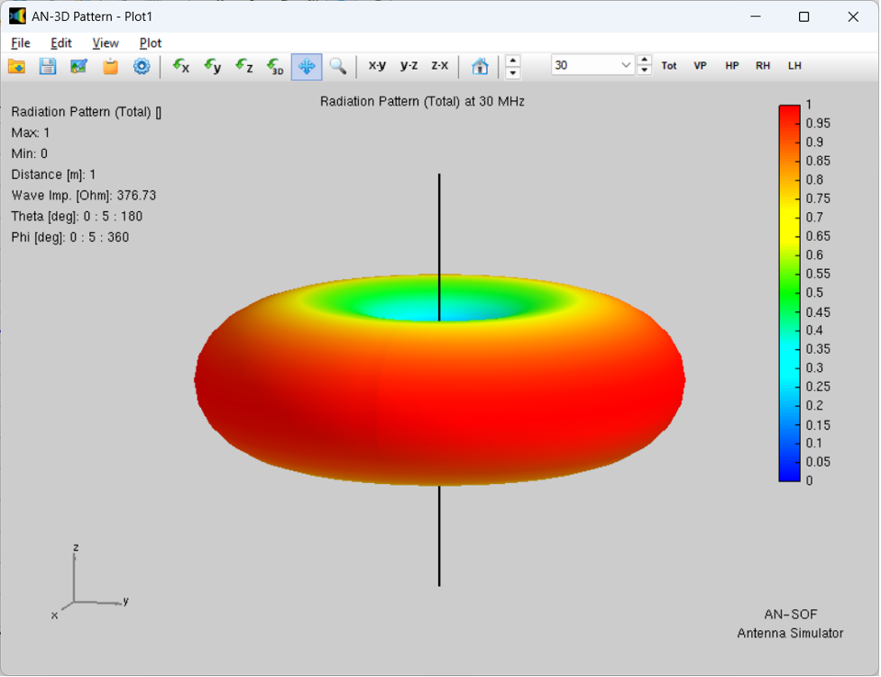
Return to the top level menu Results and create a 3D plot. Note that this appears essentially identical to the previous (improperly-tuned) dipole far field pattern.
Now let's create a far-field cut. Select top level Results, Plot Far Field Pattern > Polar Plot 1 Slice.
A pop up window appears titled Radiation Pattern Cut. Select Cut Options: Fixed Phi, then click OK. The following plot appears:
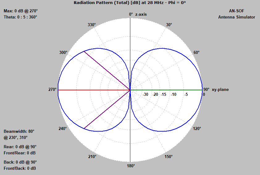
Recall that the untuned dipole 3 dB beamwidth was 70 degrees. The far-field pattern changed slightly during the resonance tuning process.
Here is a final lower-level Results tab for the updated design. Note that the VSWR is less than 2:1 across the majority of the 10 meter band.
Conclusions: 1) Tuning the antenna design takes a few additional steps, but yields better VSWR than the initial design. 2) The far field pattern for these simple antenna designs may not change significantly even when the VSWR has not been minimized through antenna tuning.
Post Summary: That's it for this post. If following along with your own simulation, you've now completed a major second-step in learning to simulate tuning parameters of antenna designs in AN-SOF. Antenna-tuning achievement unlocked! Congratulations!
Here is the main page for my AN-SOF antenna simulations.