AN-SOF Basic Vertical Antenna Simulation
This ground-mounted antenna is a DIY 20-6m version of the Chameleon Basic Vertical (CHA BV) constructed from big-box store and internet sourced components, and using a Chameleon SS-17, 17' vertical telescoping whip. The counterpoise lengths and vertical element height varies per band following the provided settings table in the CHA BV operating manual (available from the Chameleon Antenna website User Guides section).
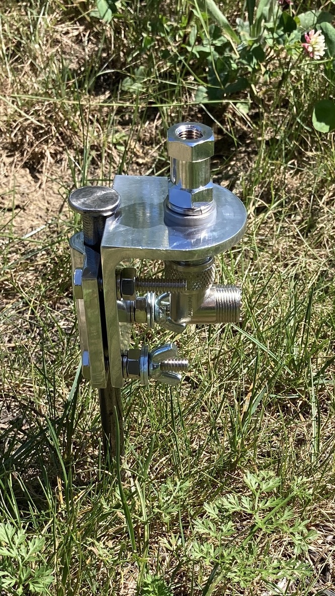
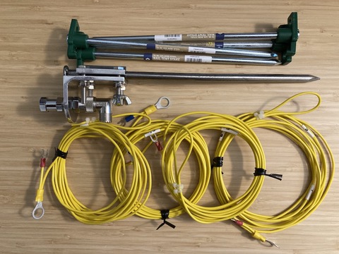
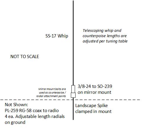
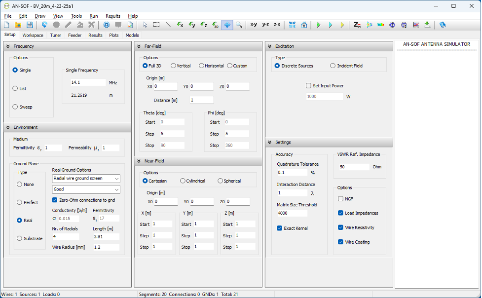
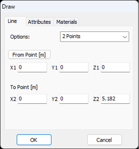
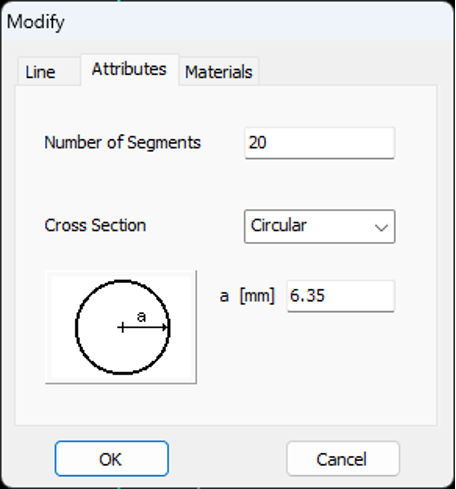
This AN-SOF simulation is performed for the 20 meter band (14.100 MHz) with four #18 gauge (1.214mm) counterpoise lengths of 12.5' (3.81m) and a fully extended 17' (5.18m), 12.7mm thick vertical element. See earlier post for the 10m vertical dipole for a step-by-step walk-through of the simulation work-flow. Analysis setup and summary screen shots are shown below for this particular antenna simulation...
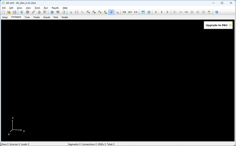
Select File > New, then setup Frequency, Environment / ground radials, and analysis parameters:
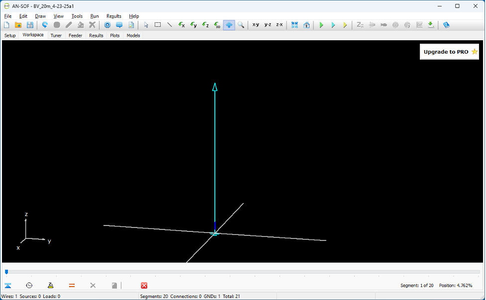
Click on the Workspace tab:
Right click on the blank workspace, pop up window appears, Draw > Line to create the vertical element, adding information for position, length, and thickness.
Set Number of Segments to 20
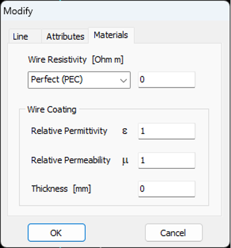
No adjustments for Materials tab are needed.
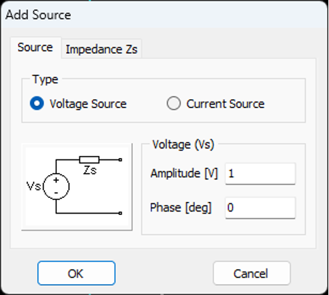
After clicking OK, you're ready for source addition. Right-click on the vertical element wire and select Add-Source. A new sub-window appears at the bottom of the window. Note that the blue slider bar is fully at the left of the window and that a dark blue segment is at the bottom of the vertical element. This can be changed by moving the slider bar left-right, which then moves the highlighted vertical segment up-down on our wire element.
Click on the small AC-source in the lower left corner of the window.
No adjustments for Impedande Zs tab are needed.
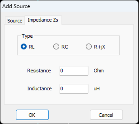
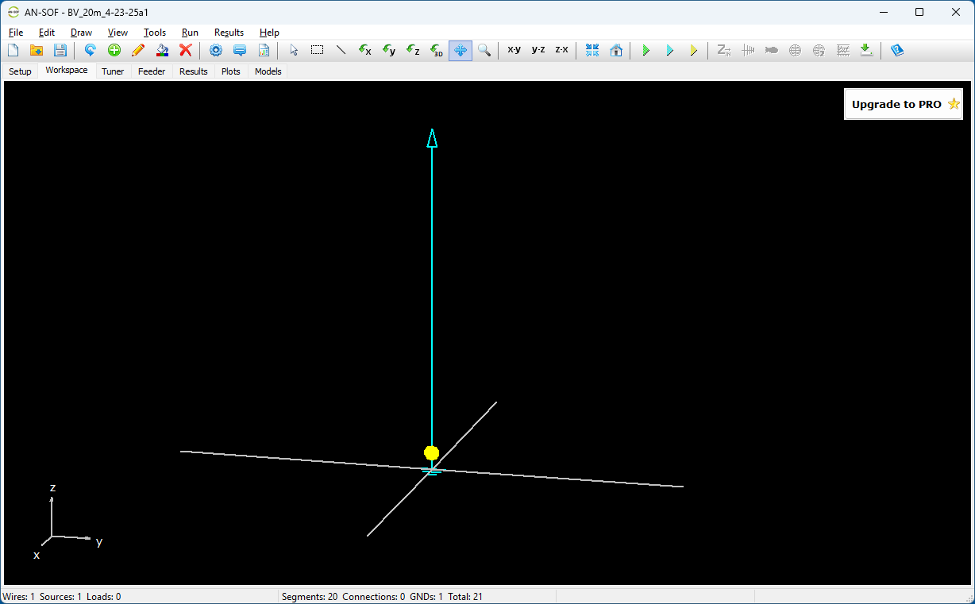
Click OK and the source is added at base of vertical element:
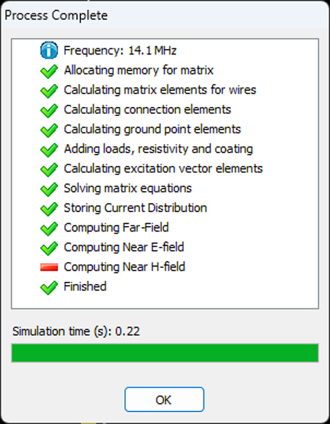
Run simulation (top level Run > Run ALL):
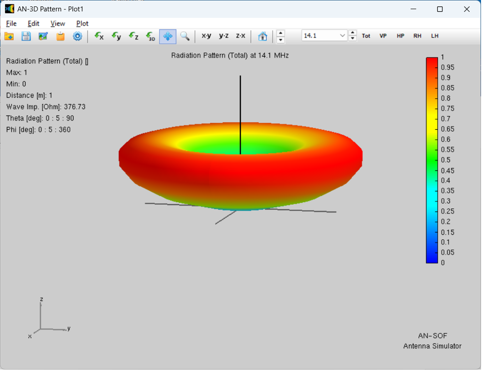
Plot 3D far-field pattern (top level Results > Plot Far-Field Pattern > 3D Plot):
Create a far-field pattern cut (top level Results > Plot Far-Field Pattern > Polar Plot 1 Slice). New pop up window titled Radiation Pattern Cut appears. Select radio button Fixed Phi, then select OK.
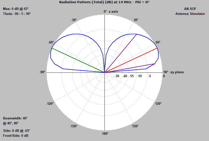
This plot provides maximum field elevation angle (65 degrees) and 3 dB beamwidth reference to that maximum (40 dB beamwidth). Changing the ground and counterpoise parameters will impact the maximum gain angle and beamwidth angles...
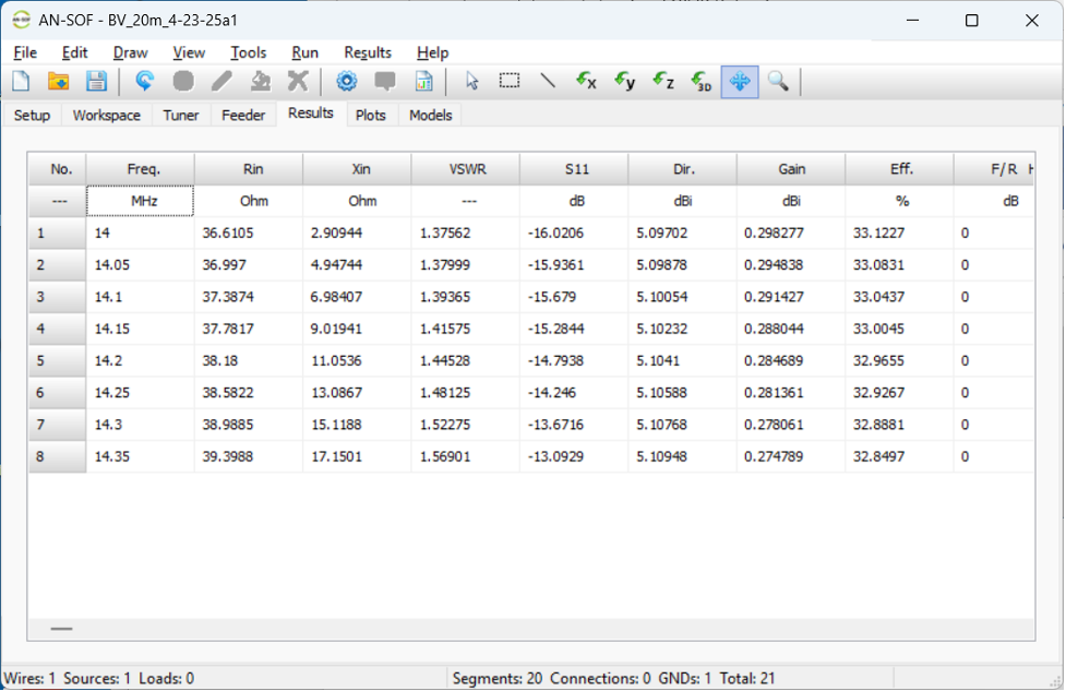
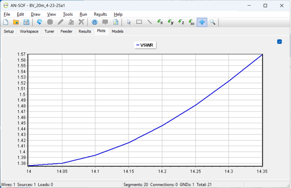
Initial simulation complete with expected far field results. Next step is to check VSWR and adjust vertical element length as needed to match desired frequency of operation (14.1 MHz).
Running the simulation again with frequencies covering the 20 meter band shows that the VSWR is less than ~1.6 across the 14.00 to 14.35 MHz band, and is slightly better at the bottom of the band than at the top of the band (i.e., antenna is slightly too long). This is a reasonable outcome for this analysis, with note that the vertical element (telescoping whip) can be easily adjusted a-bit shorter as part of the field setup.
Summary: We've completed an analysis of the 20m ground mounted basic vertical and anticipate achieving good far-field (low elevation angle) performance with a reasonable VSWR when setup with four 12.5' counterpoise and the 17' whip fully extended.
As time permits, will try to run simulations for a few of the other bands using the Chameleon BV adjustment table settings to see how far-field patterns and VSWR curves behave on higher frequency bands (18m to 6m).
Want to try simulating your antenna designs? Try AN-SOF from https://antennasimulator.com/ and begin your learning journey into the fascinating world of antenna analysis and design.
Here is the main page for my AN-SOF antenna simulations.