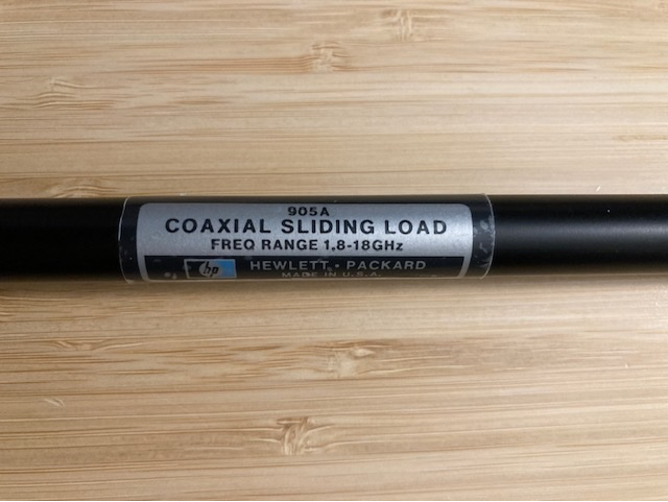
HP905A Sliding Load
<Updated 2/12/25. See new test results at end of this post.>
Today's RF Fun: Verify basic functionality of a HP/Agilent 905A sliding load using the NanoVNA-H4. Have had this in the test lab "weird stuff box" for some time without knowing if it was working or not. Today's goal is to learn more about it and see if it is working (or scrap).
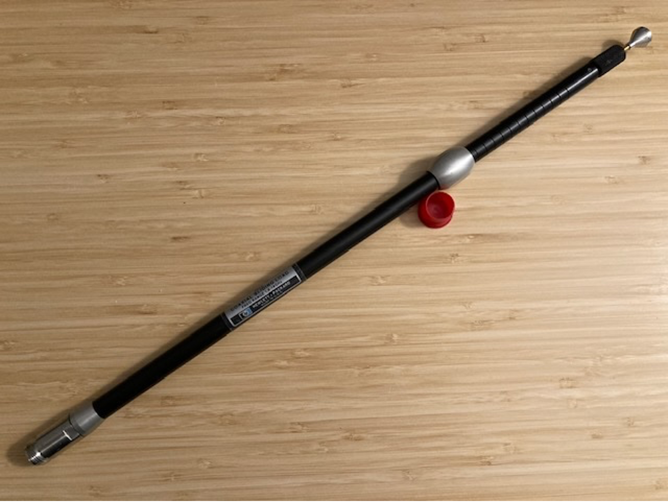
HP905A Sliding Load (1.8-18GHz) with N-Female connector. It's about 18" (~ 46 cm) long with two adjustments (silver tip for center pin connection and silver slider for load movement along length).
After VNA Open-Short-Load (S11) calibration and switch to Smith Chart display mode, here's the setup with the NanoVNA-H4.
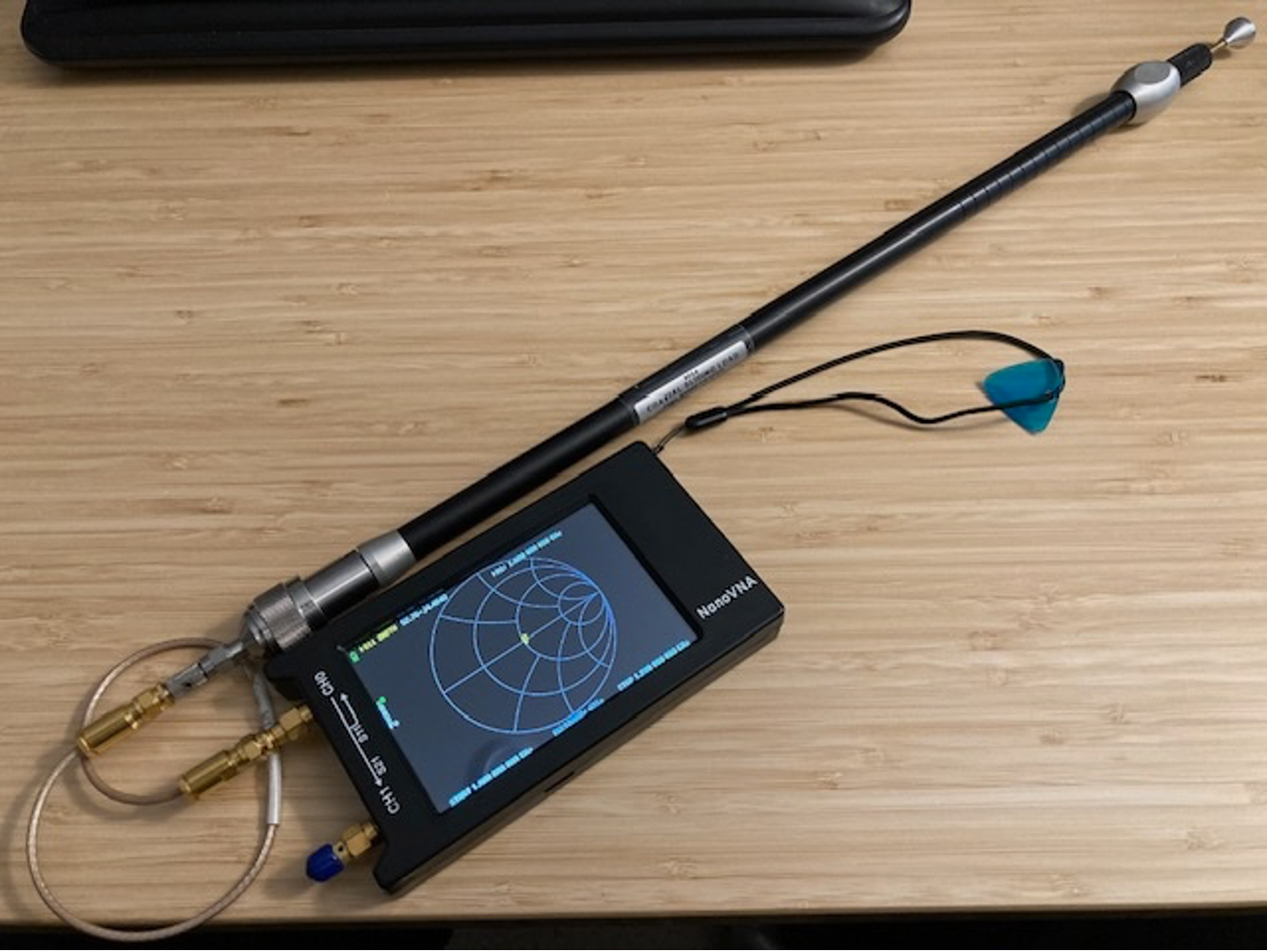
Port 1 of the VNA is connected via SMA-SMA cable to a SMA-N-Male adapter. The load's far-end silver knob controls the in-out insertion of the center pin into the N-connector test connection. There is a black knurled ring to tighten the center pin contact position once adjusted to mate at the N-Female end. With these connections made, it appears that the sliding load works! (i.e., The measurement point is in the center of the Smith Chart -- and not at the left side [shorted] or the right side [open]).
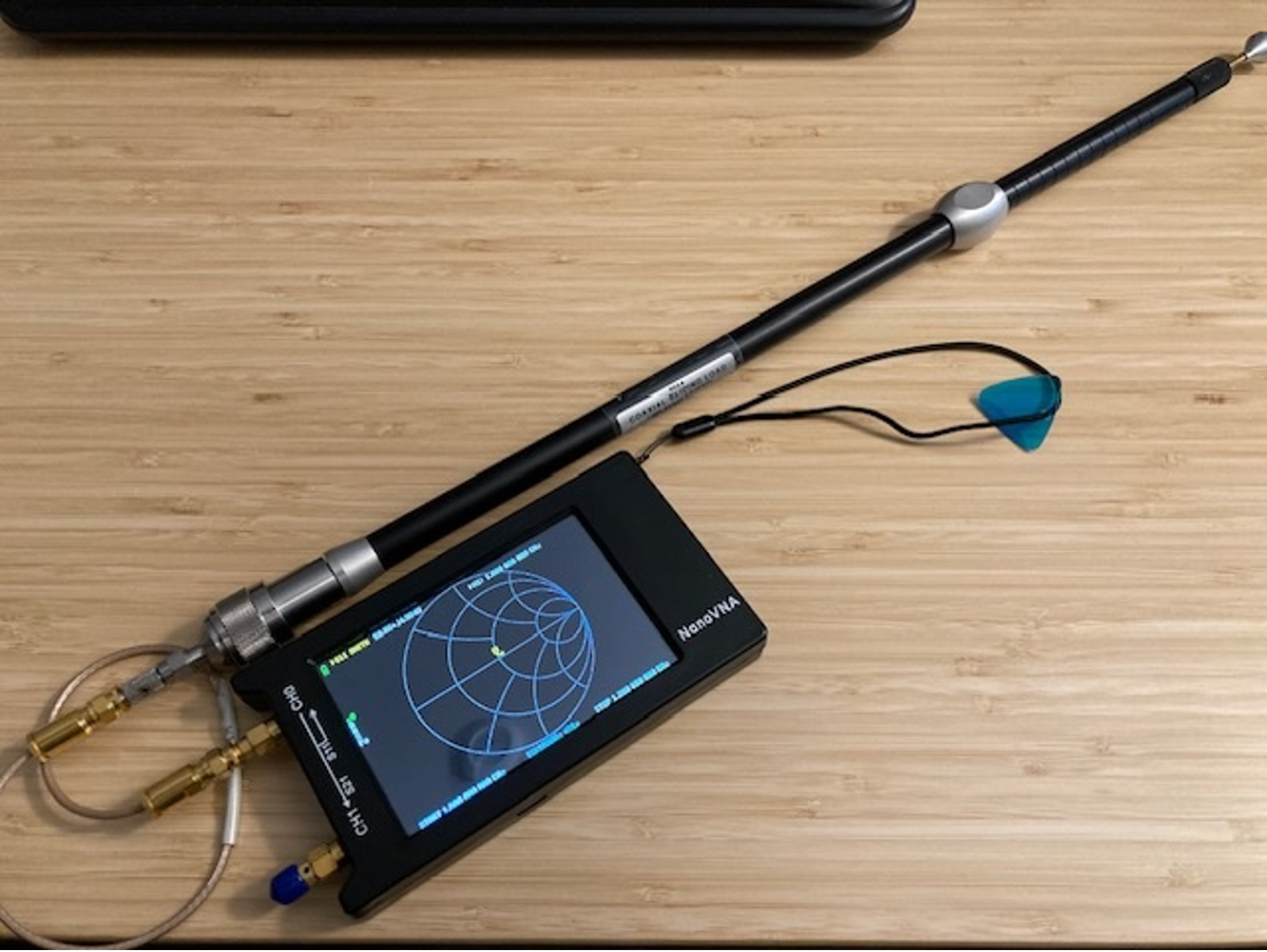
Note the sliver sliding ring on the load is fully extended for the above photo. Next, the sliding load silver ring was slowly moved to the fully inserted (left) position while watching the VNA display. The measurement point slowly moved around the center load point with no jumps or crazyness in the data.
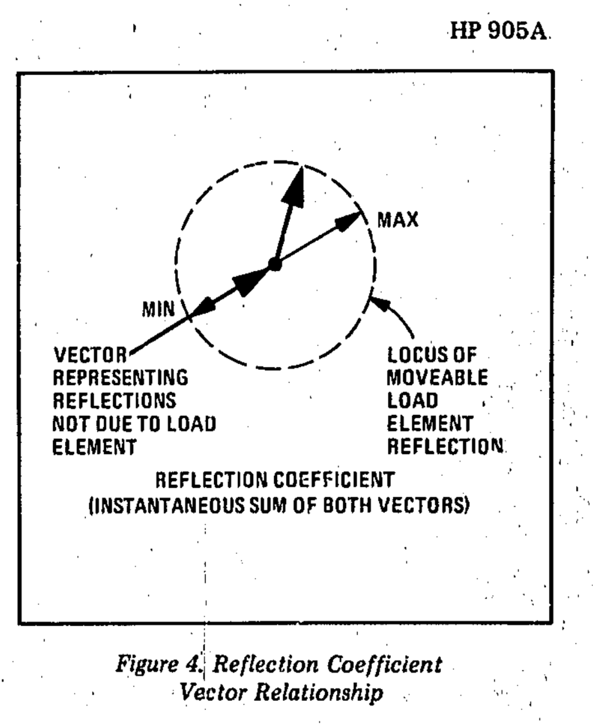
A screen grab from the manual shows this similar plot:
Knowing this appears to work is the positive news for the day. Given the majority of my home activities are only up to 6 GHz, am not sure if this will be a useful item for the lab (given load's frequency range of 1.8-18GHz).
The load's manual says something about multiple connectors, pins, and a wrench was originally provided in the kit. (Have just the sliding load with the installed N-Female connector.)
Will add this to the Extras page and see if anyone is interested in it for their lab.
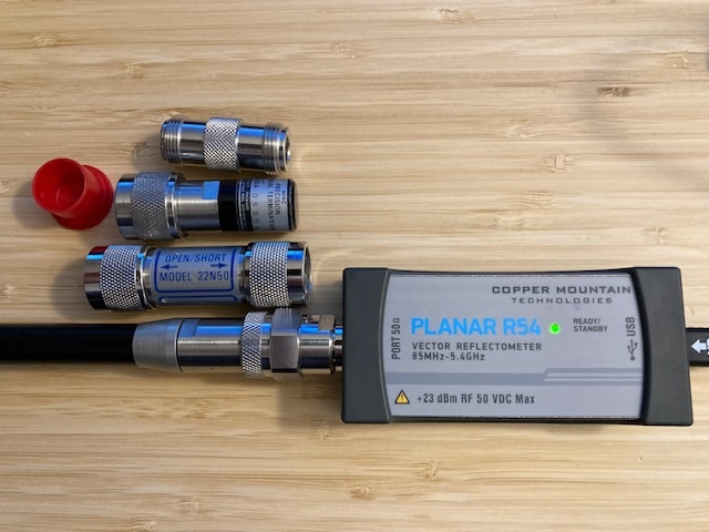
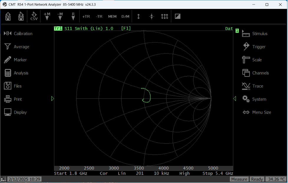
Updated 2/12/25: Repeat test with Copper Mountain Technologies R54 Vector Impedance Probe over range of 1.8 to 5.4 GHz.
Below is CMT R54 vector data with load at shortest length (slider IN).
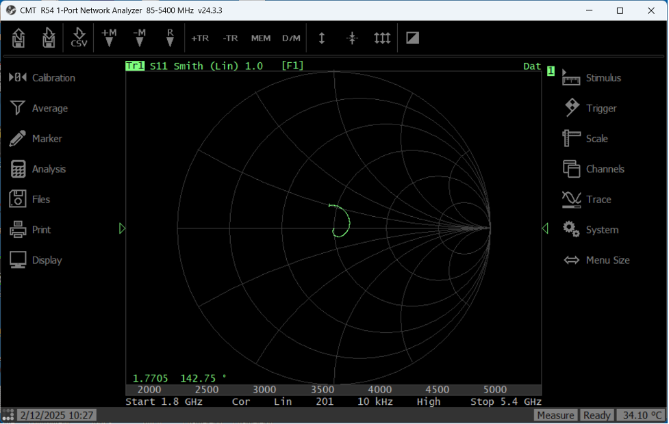
Below is CMT R54 vector data with load at longest length (slider OUT). Did not observe any data drop-outs/shifts when sliding the load along the length.
These are really subtle differences in the data between the two load extremes.
Overall conclusion: Glad to see this works and recognize that it is unlikely to be used regularly in my home lab... Will add to Extras page to see if anyone is interested in it.