RF Circulators Part 1
Seeing a recent post for a ham's new RF circulator on Mastodon brought to mind that I had a few circulators in the lab's modular RF components box and that the ADALM Pluto SDR with SATSAGEN would be an ideal setup to quickly test them with little fuss.
Have had thoughts towards putting together a 902 MHz radio based on one of the Pluto SDRs with filters from the KK7B transverter boards (would only use the printed 902 MHz TX/RX filter sets on the board, not the mixers or 758 MHz local oscillator). The separate TX/RX ports on the Pluto and the two separate TX and RX filter sets on the KK7B boards would best be applied to a single TX/RX antenna. A transmit/receive (T/R) switch might do that, as would a RF 3-port circulator. This was the purpose of today's test - determine if an on-hand 900 MHz circulator set might work in a future 902 radio to combine transmit and receive functions to a single antenna.
Below is the modular RF components circulator collection with a few cables and one of the Pluto SDRs.
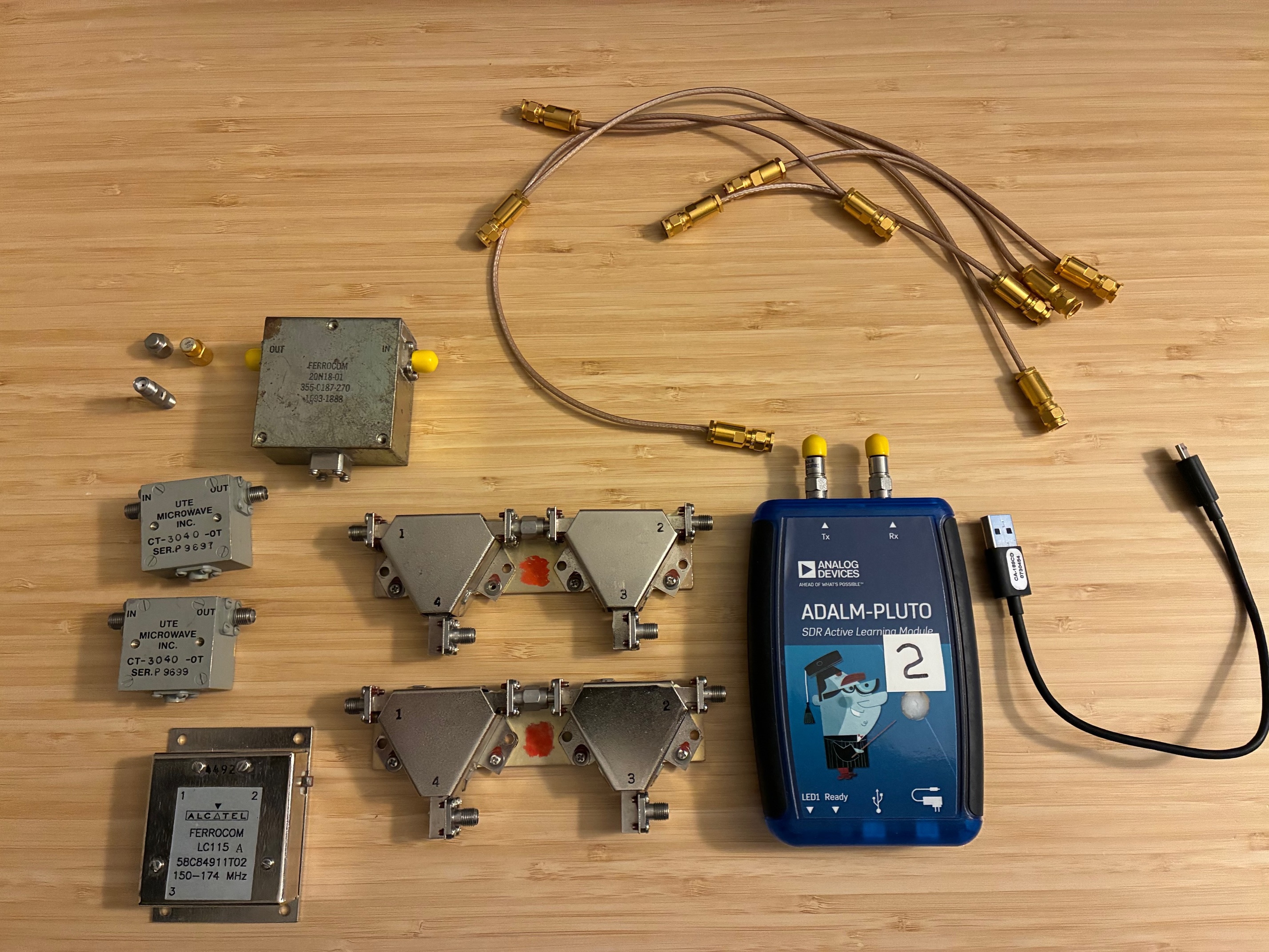
The double circulator sets were thought to cover the US 800-900 MHz cellular band. Let's test and see if that is true.
A quick note about these three port circulators (or a pair of them as connected together in these sets). Port 1 is the RF input (transmitter). Port 2 is the RF output (antenna). Port 3 is reflected (or received) power from the Port 2 connection. Port 4 is the reflected signal coming back from an unterminated signal from the circulator closest to the antenna connection (Port 2).
With the transmitter operating into Port 1, signal at Port 3 is low if Port 2 is terminated. If the antenna is somehow disconnected or fails at Port 2, then the transmitter power is routed back to Port 3, protecting the Port 1 transmitter power from reaching (reflecting) back to that port.
For a low-power transceiver, the transmitter connects to port 1, the antenna connects to Port 2, the receiver connects to Port 3, and a 50 Ohm termination is applied to Port 4. Ideally a RF limiter is placed between the circulator Port 3 and the receiver's input connection. This protects the receiver from reflected power should the antenna fail or be disconnected (while operating in full-duplex mode).
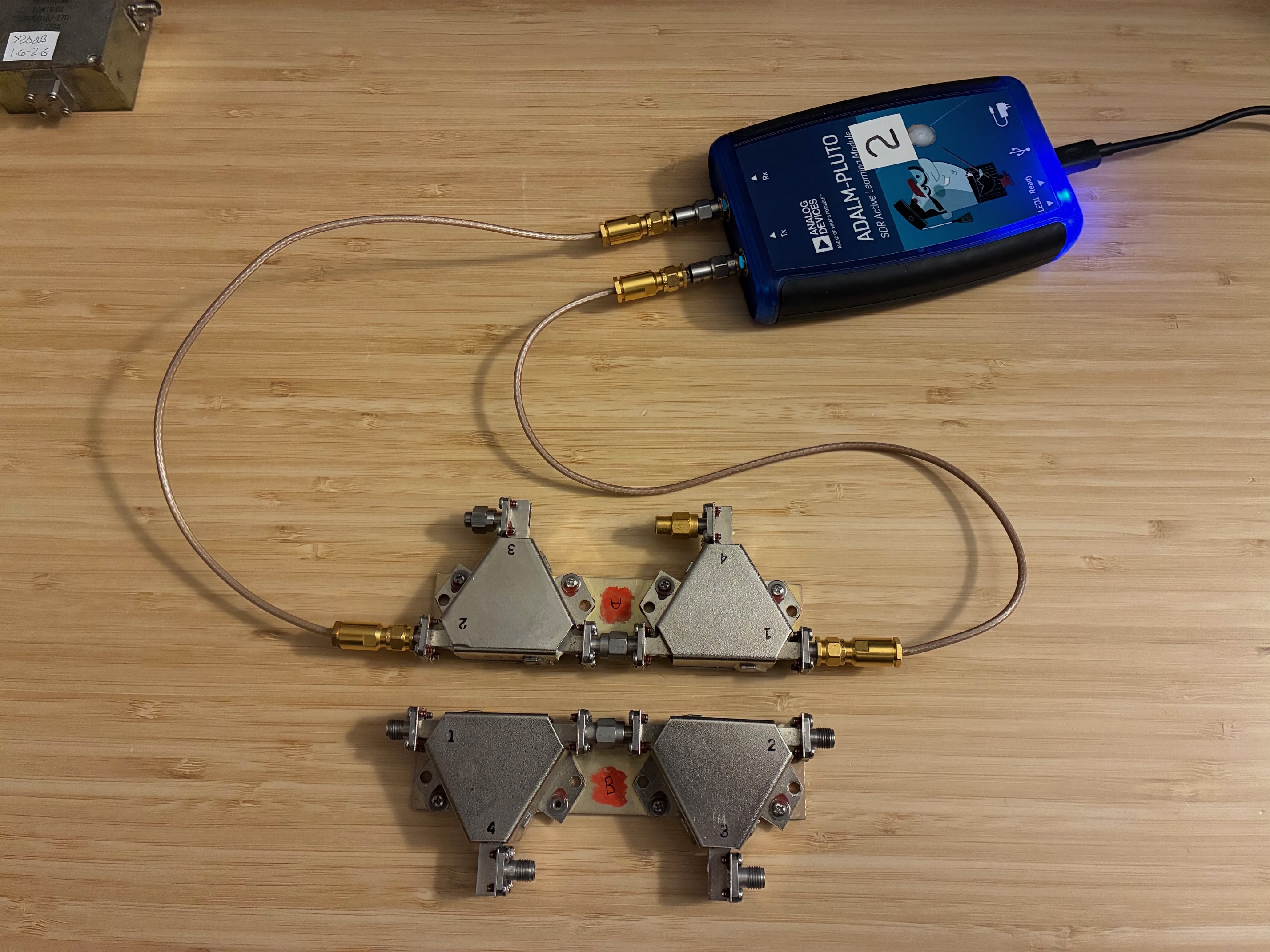
The first test is to monitor the insertion loss from Port 1 to Port 2 that the transmitter signal is routed through. Would like this to be less than 1 dB (and ideally as little as possible). Below is the setup for the forward, through insertion loss test. Terminations are applied at circulator Ports 3 and 4 for this initial test.
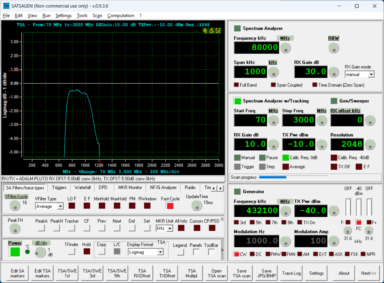
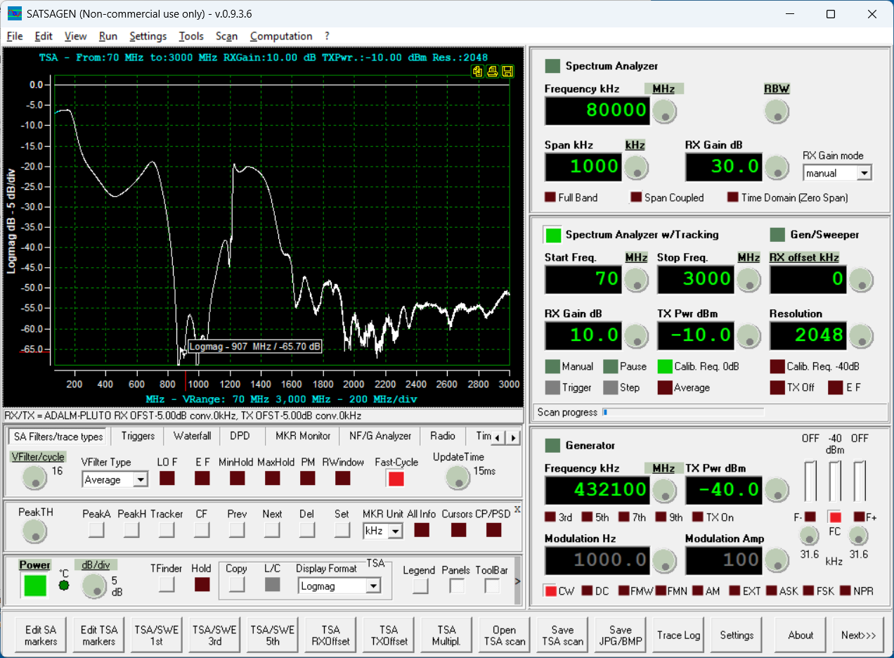
Using SATSAGEN with the Pluto makes this easy. The insertion loss curve should be close to the reference zero line at the part's design frequency. (Is this ~ 900 MHz?)

The above measurement indeed shows that the forward insertion loss is low in the 900 MHz band. Below is a screen capture with a zoom in on the vertical (amplitude) scale. The insertion loss looks to be about 0.5 dB at 902 MHz.
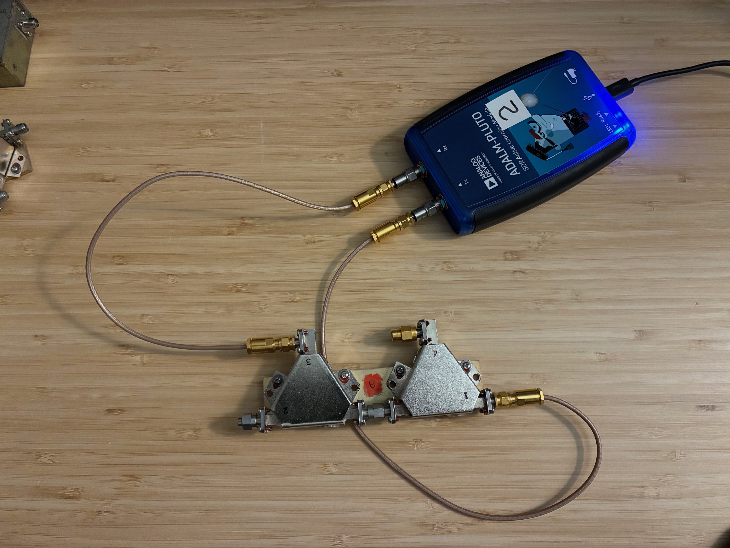
The second setup measures the loss that a receive signal would have coming in the antenna connection (Port 2) and being routed to the receiver (Port 3).

The below SATSAGEN screen shot shows that the receive path is less than 0.5 dB insertion loss. This is pretty good and supports operating full-duplex with the future 902 MHz transceiver.

It is good to know what the transmitter to receiver isolation would be for the proposed 902 MHz radio set. The setup below measures isolation between Port 1 and Port 3 of the circulator.
The screen shot below shows between 25 and 30 dB of isolation on this path (with a well terminated/matching antenna attached to Port 2). This will be good enough for the 902 MHz radio with a RF limiter being added for protection against a failed antenna at Port 2.

There is just one more measurement to make: If the antenna fails or becomes disconnected, what level does the reflected transmitter signal arrive at back at Port 1?
This test applies the Pluto TX port to the circulator Port 2 and the Pluto RX port is connected to the circulator Port 1 connection (the reverse of the second photo connections above). Here is the SATSAGEN curve showing circulator reverse isolation.
With approximately 65 dB of reverse isolation, this dual circulator setup provides excellent protection to the transmitter against inadvertent antenna failure or disconnection.
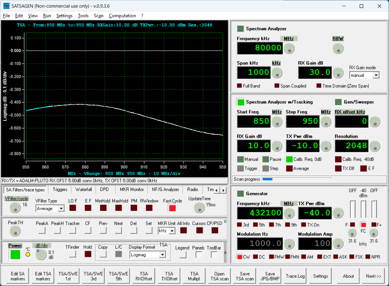
As a last test, I went back and narrowed the frequency sweep from 850-950 MHz. This yields a much smoother response curve for both forward (1-2) and receive path (2-3) measurements. Below is the forward path (1-2) measurement. It's easier to see that the insertion loss will be just under 0.5 dB at 902 MHz. Given there are two circulators in series on this path, if less transmitter insertion loss (power loss) is needed, than I can just disconnect one of the circulators (using just one instead of two) to cut the TX path loss down to about 0.25 dB. This may be implemented later when (if) the 902 transceiver comes to life! Trading more transmit range verses (largely unneeded) reverse isolation is probably a good idea.
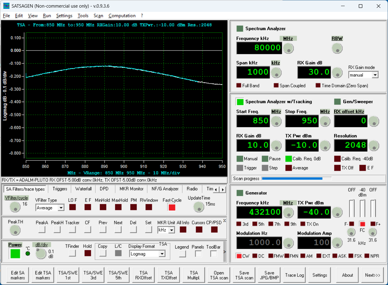
Below is the receive path (2-3) showing under 0.2 dB from the antenna port (2) to the receiver connection at Port 3.
That's it for this test sequence and post. The 900 MHz circulator sets (A & B) both work approximately the same and are ideal candidates for use in a future 902 MHz radio system (even providing full duplex capability as needed).
For more on circulators see this follow-on second post.
All author photos captured with an iPhone 16e.