RF Circulators Part 2
The first post on the topic of RF Circulators covered measurement setup, test sequence, and test results for two sets of dual 900 MHz circulators, with the goal of determining usability for a future 902 MHz transceiver. This second post covers measurements on a few other circulators in the lab's modular components box.
First up is a Ferrocom 20N18-01 in a 2" by 2" by 1" housing with two SMA female jacks (marked IN and OUT). The third port of this circulator is a built-in termination along the bottom edge of the case. Note: Two-port, built-in termination devices may also be called an "Isolator". There were no frequency coverage markings on the case. Measuring this device using the ADALM Pluto with SATSAGEN yielded forward insertion loss and reverse isolation curves.
The SATSAGEN screen capture below shows minimal insertion loss from approximately 1.6 to 2.0 GHz for the forward loss measurement.

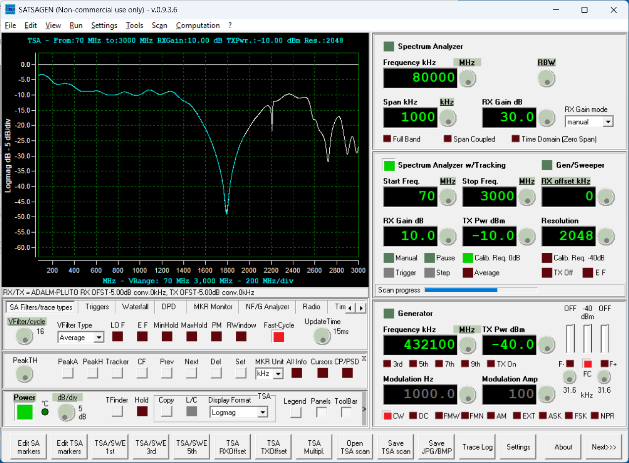
The SATSAGEN screen capture below shows more than 20 dB of reverse isolation from approximately 1.6 to 2.0 GHz for the reverse path measurement.
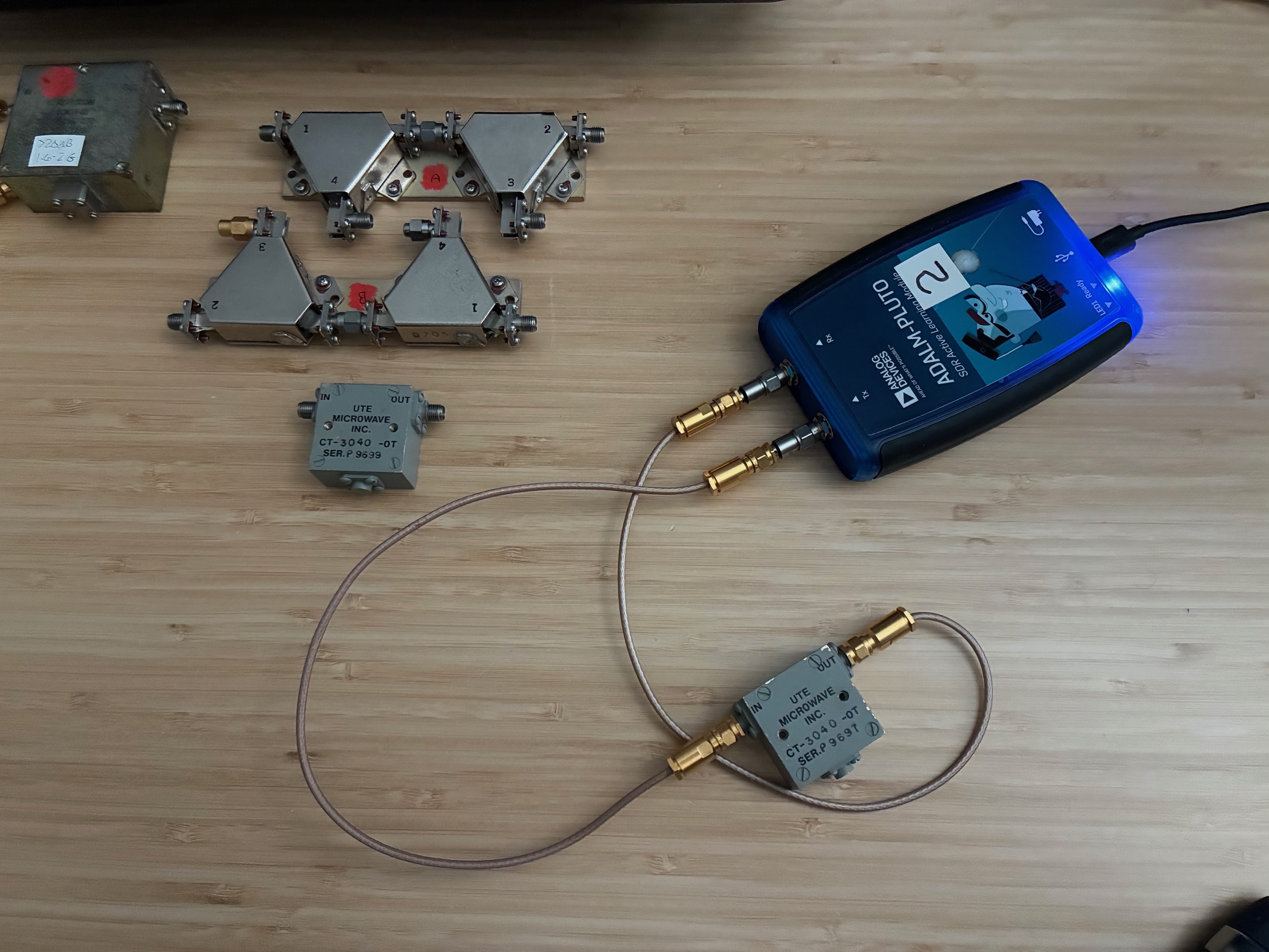
Somewhere along the line, I acquired a good quantity of UTE Microwave Circulators and Isolators: 8 ea CT-3040-OT (2-4GHz with termination), 3 ea CT-3042-O (2-4GHz without termination), 3 ea CT-3036-OT (1.6-3.2GHz with termination). See my Extras page for a photo and additional information on these devices.
I measured two of the CT-3040-OT (with termination) isolators today just to confirm their usable frequency and reverse isolation capabilities.
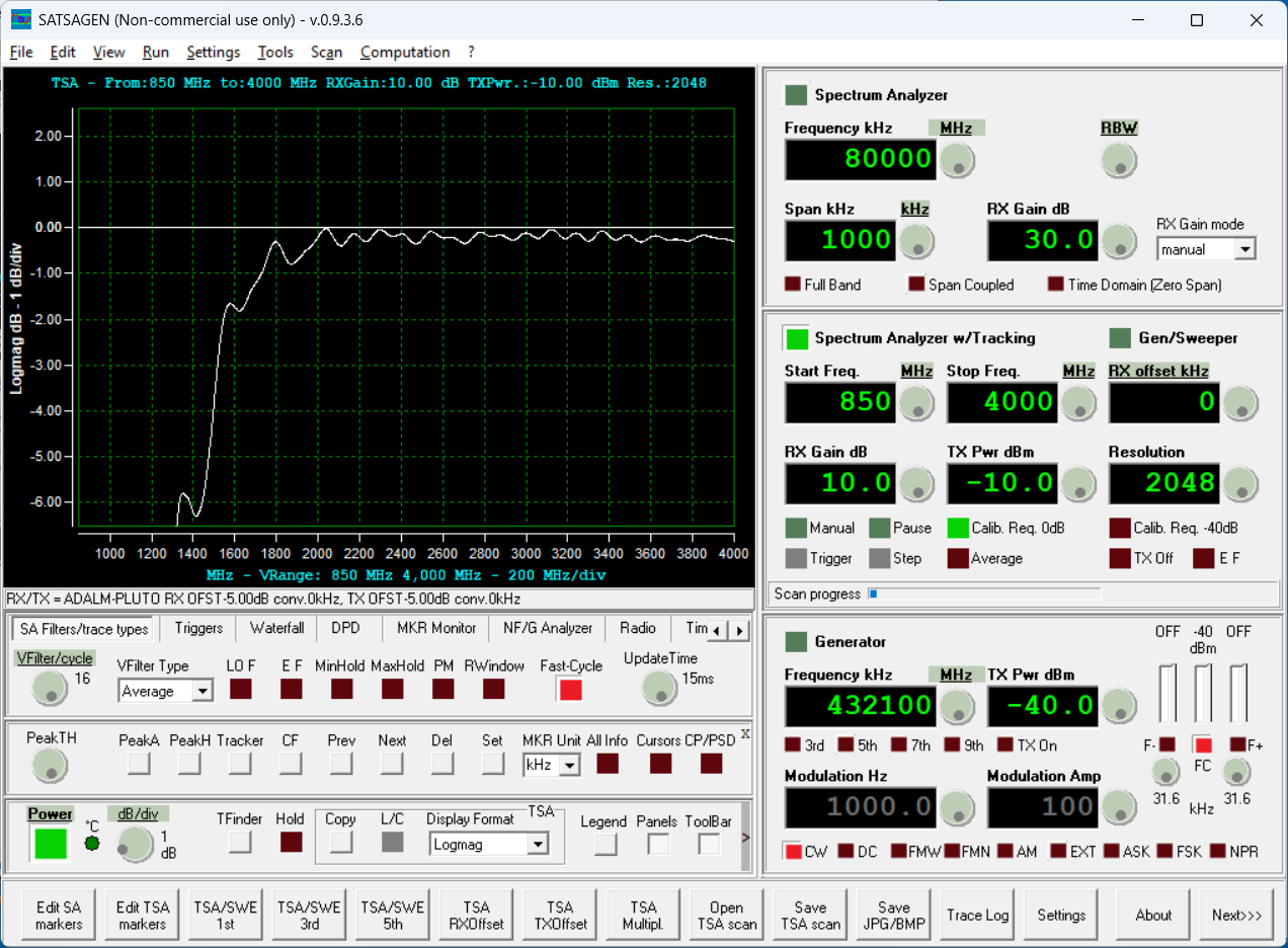
The SATSAGEN screen shot shows reasonably low forward path insertion loss over quite a large range (from maybe 2 to almost 4 GHz). With this large range, it might be better to look at the reverse isolation performance to discover where to best use this model of isolator.
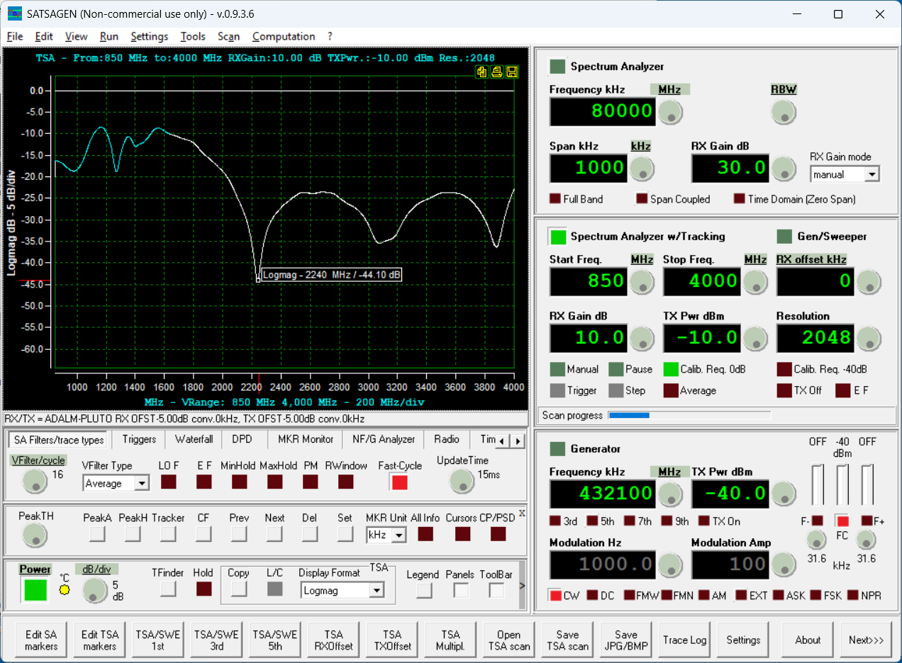
It's a bit of a surprise to see that the reverse isolation is very broad and offers greater than 20 dB isolation from approximately 2 to 4 GHz. These are very broad band devices...
The last type of circulator is a non-connectorized unit that is designed to bolt and solder into a circuit board/housing application. I was unable to test this device today, but wanted to share photos of it so readers can see how a circulator might be added into a transmitter or amplifier without using expensive SMA and coax interconnections.
This Ferrocom LC115A device is approximately 2 x 2 x 0.5 inches and has three solder tab connections. Ports 1 and 3 are on the left side of the case.
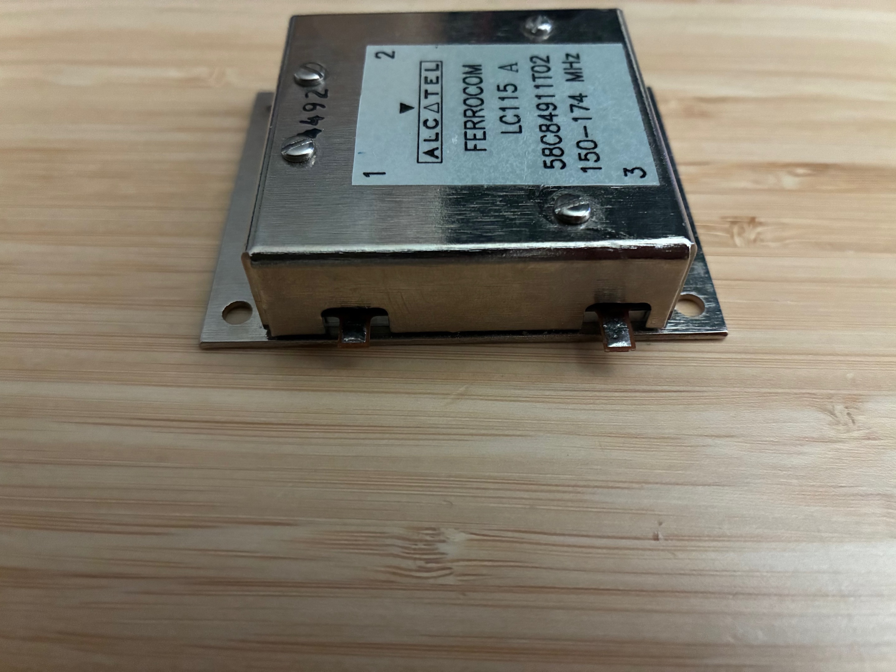
Port 2 is on the right side of the case. The mounting flanges indicate that the unit is intended to be bolted down into a chassis with printed wiring board solder connections made to the three tabs sticking out of the sides of the case.
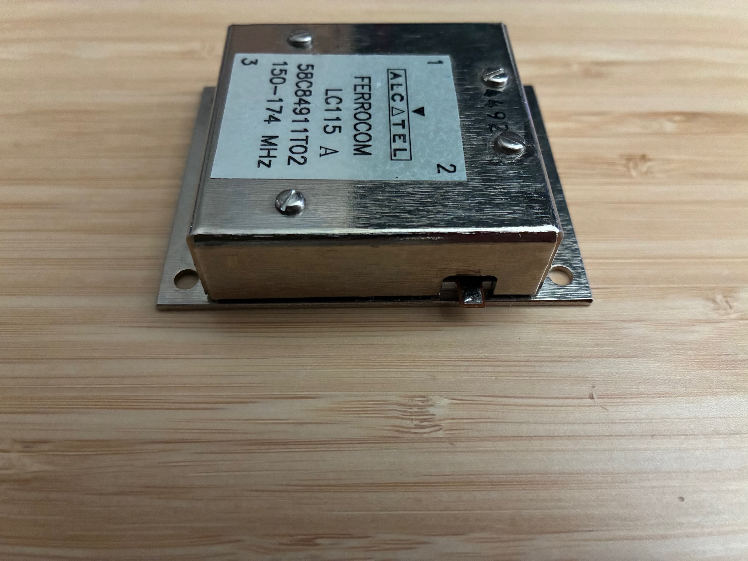
I was unable to find documentation on this device and would guess that it offers some performance down in the 2-Meter ham band and maybe works up to 40-50 Watts of transmitter power. Maybe with some extra time, copper tape, and some RF connectors, I'll be able to measure this unit someday. Until then, back in the modular RF components box it goes...
That's the end of RF circulator measurements for now. Looking forward to using one or two of the 900 MHz band circulators in a future SDR transceiver for that band. In the meantime, I need to setup and measure the KK7B PCB RF Filters to see how they might work for a proper RF front-end on the Pluto SDR. More fun ahead!
All author photos captured with an iPhone 16e.