RF Noise Source Part 3
Moving on from the second posting on this topic, and with the Noise Com NC3404T noise source known to be working, it was time to see what the lower frequency limit might be and if the coverage was reasonably flat. Setup the TinySA-Ultra spectrum analyzer (LNA = ON and 0 dB attenuation) to take a look at the noise over lower frequencies.
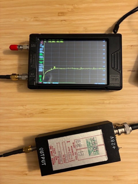
This test showed the noise source was reasonably flat down to the 2 meter ham band (144 -148 MHz). The signal could be seen to be steadily falling off for frequencies below that.
Since SATSAGEN can control the noise source on/off state automatically (via an Arduino USB virtual serial port), I put together a protoboard controller interface to see the benefit from auto vs manual modes with the software. The author provides the Arduino sketch and instructions on how to modify the code to fit into your Arduino board (UNO for my case). With the sketch edited/loaded and selecting the board interface in the SATSAGEN software setup pages, I was able to control the noise on/off state automagically using SATSAGEN. (This involved some background reading on SATSAGEN and how to configure/control it. TIP: Be sure to read the native Italian pages and not just the English pages provided. There are a few differences between these that might cost you time to figure out.)
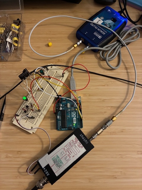
My particular noise source module has a "TTL Control" labeled pin on the end opposite the RF output port. This control pin has a (with +28VDC power applied) voltage of approximately +12VDC. With the pin open, the noise source is ON. With the pin shorted to ground, the noise source is OFF. The SATSAGEN author helpfully provides schematics and diagrams for controller interfaces with a noise control signal output on the Arduino UNO D12. I put together a simple transistor interface with a open-collector connection to the noise source "TTL Control" pin. This worked well to confirm all was operating as it should under program control.
Faced with another packaging challenge (building a small hand-wired interface board and then putting it safely into a easily usable enclosure), I remembered that I had a few Velleman KA05 relay control boards in the Arduino box-o-parts. The thought was to just use one of the SPDT relay output connections to short the noise source control pin to ground when commanded off, and let if float open when the noise source should be turned on. The relay with the white "NS" marker on it is the controlled relay via D12. It clicks on and off under program control as SATSAGEN works to measure noise gain and the calculated noise figure. A small red LED is next to each of the relays to indicate when it is energized. For the photo below the noise source is OFF. (The far end relay is always on when SATSAGEN is controlling the UNO. Using that as a "power applied" indicator for the moment.)
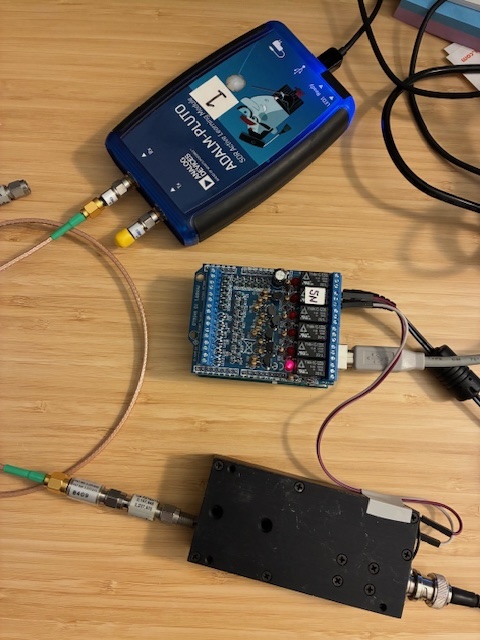
This new Arduino/Velleman based noise control function is much cleaner and easier to setup and use than the protoboard with the flying leads and parts ready to be dislodged and fall out. The Arduino UNO with KA05 on top is stored in a small ESD bag and simply pulled out on the bench when needed. With this resolved, the setup was now ready for some trial measurements to learn how to use this new lab capability.
First up: Measuring a Mini-Circuits ZHL-1042J amplifier that I had previously packaged into a surplus Amplifier Research LN-1000 enclosure that had a blown amplifier module within. The replacement RF amplifier provides greater than 25 dB gain with a noise figure of just over 5 dB over the majority of the 10 to 4200 MHz frequency range.
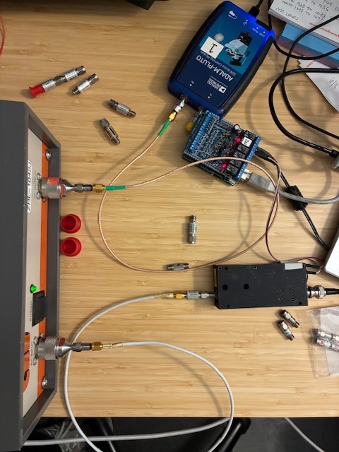
A great feature of the SATSAGEN software is that it automatically calculates the maximum gain allowable for the device under test (DUT) amplifier (and displays a warning yellow or red results number color if that gain is exceeded at the DUT). It took a few trials to get the proper value attenuators in the correct places across the setup. For this test I ended up with a 5 dB pad on the output of the amplifier. This is reflected in the gain number below being reported as 5 dB under the amplifier's actual gain. The reported gain number is green, indicating that I have the correct noise levels set via the various in-line attenuators added to the circuit.

This measurement was a great confirmation that the new gain and noise figure test setup was yielding reasonable results. Working noise figure setup Achievement Unlocked!
Summary of Activities:
1. The NoiseCom noise source was confirmed to be working.
2. A dedicated +28VDC supply was put together to power the noise source.
3. A noise source on/off interface was constructed and the source confirmed to be properly controlled by SATSAGEN.
4. The new setup was used to measure an on-hand Mini-Circuits ZHL-1042J RF amplifier at 2.5 GHz, confirming measured values align with the manufacturer's data sheet.
Future thoughts: Measure a few more RF amplifiers and maybe explore making a lower frequency noise source for ten to six meters. More fun ahead!
Author photos taken with an iPhone-16e.