RF Noise Source Part 1
Have had a Noise Com NC3404T RF noise source for some time now, and didn't know if it was actually working (or was just a deadweight chunk of metal with RF connectors on it).
A rainy day today was a good opportunity to examine it a little closer and apply power to see what could be learned.
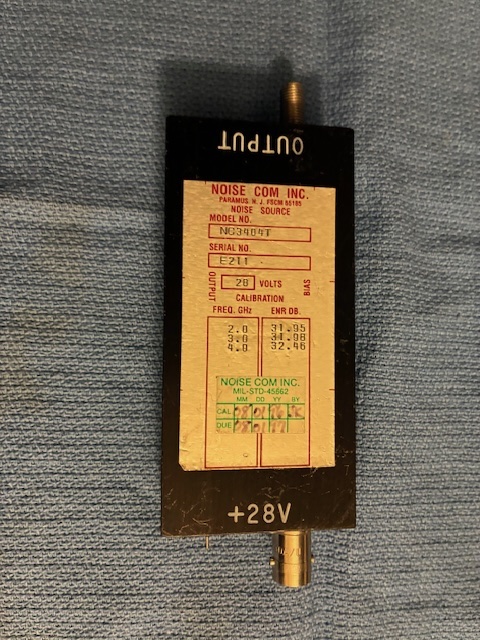
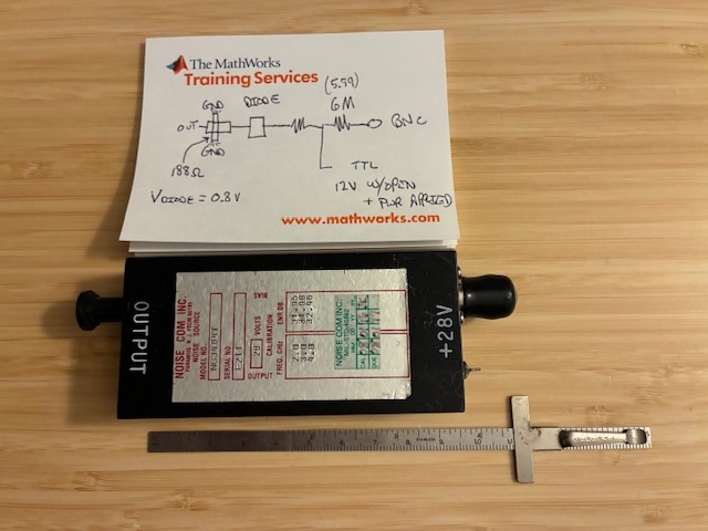
The case is about 3.75 inches in length, just under an inch thick, and about 1.75 inches in width (without connectors/connections). It has a BNC jack for application of 28 VDC power, a feedthrough connection labeled TTL for on/off control and a SMA jack for noise output.
The unit has Excess Noise Ratio (ENR) values printed on the label for 2, 3, and 4 GHz. A calibration sticker from 1996 is attached below the ENR value table.
After removing 10 screws from the backside, the interior contents are visible (not much to see here).
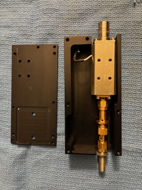
The TTL control wire from the feedthrough routes into a hole on the side of the metal noise source package. Three SMA adapters are used to extend the SMA jack on the source housing to the outside of the larger black metalic enclosure.
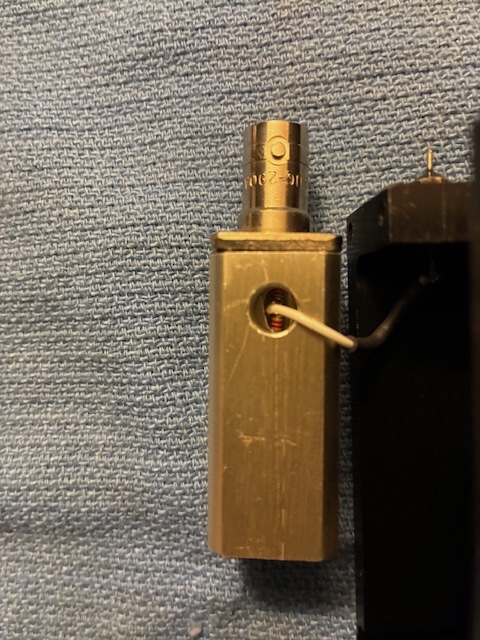
Not exactly sure how they built this unit, as it appears that the white wire leading inside to a resistor connection was soldered after assembly (soldered through the little hole visible).
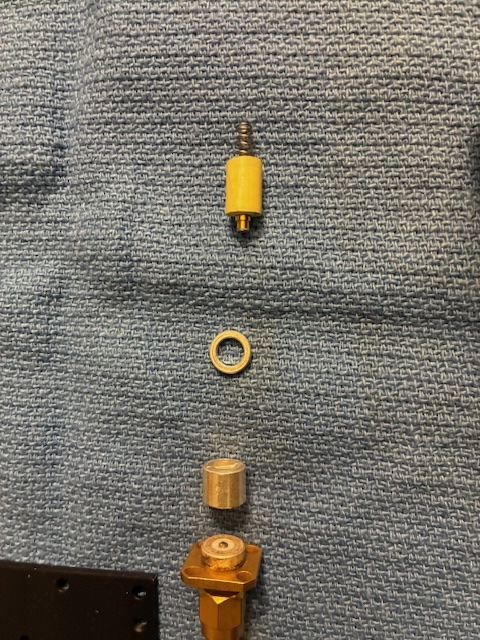
Removing the housing screws for the SMA connector and taking out a small length of circular metal (with apparently a transmission line running through the center of it) reveals one end of the noise diode.

The output components are laid out below in order from bottom to top: SMA connector, small tubular transmission line, metal spacer, noise diode with tape around outer connector part and spring connecting to top side of noise diode. The spring connected inside the noise housing to what looked like a formed lead (likely part of a resistor divider from the power-input/TTL control connections.
Made a few measurements while the unit was disassembled. The input dropping resistor from the +28 VDC BNC input to the TTL control line measured ~ 6 Meg Ohms. The Noise diode indicated ~ 0.8 VDC with the DMM's diode check function. The small black colored end of the transmission line measured ~ 188 Ohms from the line to the grounded housing structure. A rough diagram of the noise source is sketched on the pad below.
With the unit reassembled, I was unable to see any difference in noise level with the TinySA-Ultra during a quick power-on check. I found that the open circuit voltage on the TTL control line was ~ +12V (not a major concern with that 6 Meg Ohm series resistor inside the noise housing). Belief is that the noise level is just too low for the TinySA to see without further settings/investigation.
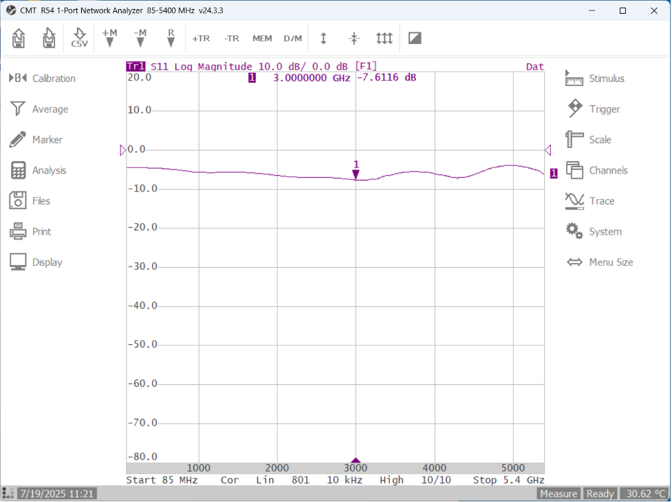
Had the thought to check the SMA connector's return loss to see if the output might be open, shorted, or present a good match into a 50 Ohm coaxial connection. Used the Copper Mountain Technologies R54 vector impedance probe to examine the SMA output's return loss. First up is power-off (not expected to be very good, but not open or shorted either).
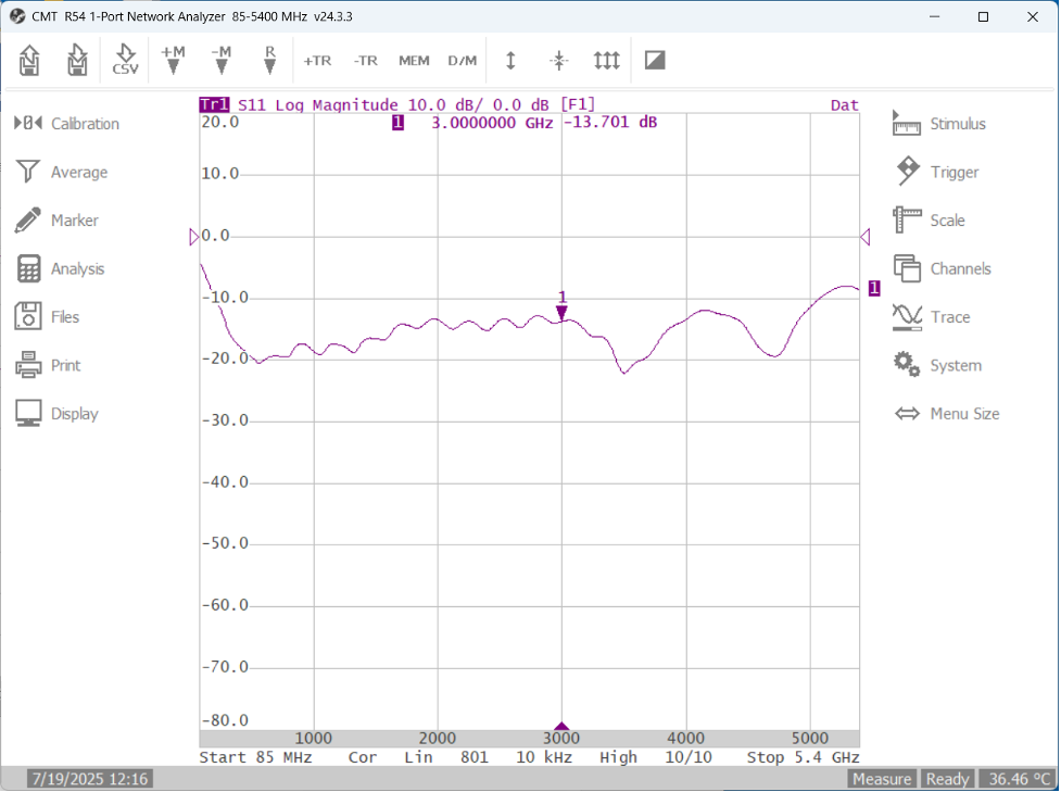
Next, +28 VDC power was applied to the BNC jack. The return loss improved quite a bit.
Shorting the TTL control pin to the BNC jack ground turns off the diode voltage supply and the output return loss changes back to the above power-off graph's state.
Here is the output return loss with the TTL control pin open (no connection).
With this finding, I now have confidence that this noise source is likely working properly. Next step is to add some RF amplification (one or more modular RF amplifiers added to the output) to see if the TinySA-Ultra can see the noise source being turned on and off.
It will be interesting to see how broadband this noise source actually is - as there did not appear to be much of a filter/matching circuit between the noise diode and the output SMA connector. Hope to use this source much lower than the 2 GHz ENR value printed on the label.
Part 1 complete (power up - no smoke - seems to do something output match wise).
Checkout Post 2 to continue following this story.
Author photos taken with an iPhone-16e.