Testing an Analog RF Attenuator
The home lab's modular RF component stock includes a pair of Mini-Circuits ZFAS-15 Attenuators. These are three-port, SMA-female connectorized attenuators with a frequency range of 10 to 2500 MHz. An internet search failed to come up with a data sheet, with the above frequency range found on a random ebay listing. Mini-Circuits does have a data sheet for a similar part number analog RF attenuator ZFAS-2000 which covers 100 to 2000 MHz.
The goal of today's test is confirm functionality of the two ZFAS-15 components and to learn how what appears to be a common double-balanced RF mixer can operate as an attenuator under varying DC control.
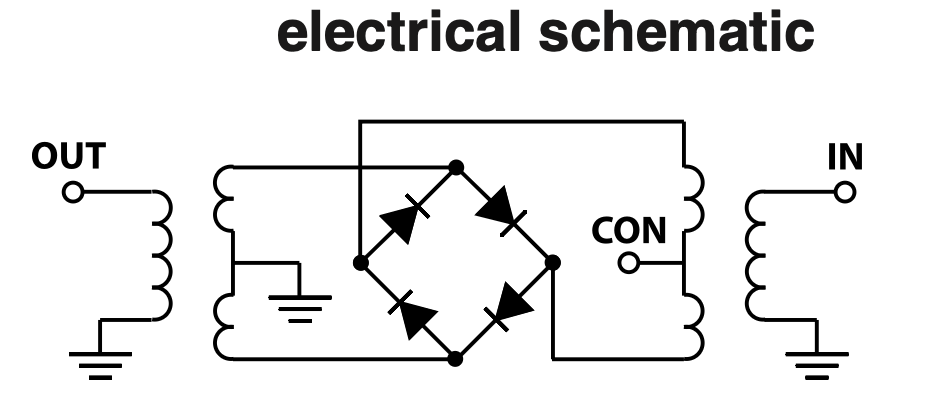
Let's start with the ZFAS-2000 schematic which shows it is indeed similar to a common 3-port RF mixer.
Compare this to a Mini-Circuits SBL-1X RF mixer schematic.
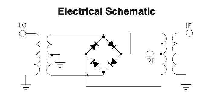
Indeed, these are very similar... For the attenuator, a DC voltage is applied to bias one pair of the diode bridge into conduction. The RF mixer has the standard Local Oscillator, RF, and Intermediate Frequency ports. For the ZFAS-15, the two RF ports are labeled as Out and In, with interchangeable connections likely possible. For the mixer, the LO and IF ports are optimized for low loss and maximum isolation through the device. These two components are possibly dual-function in functional capability. Let's test and see.
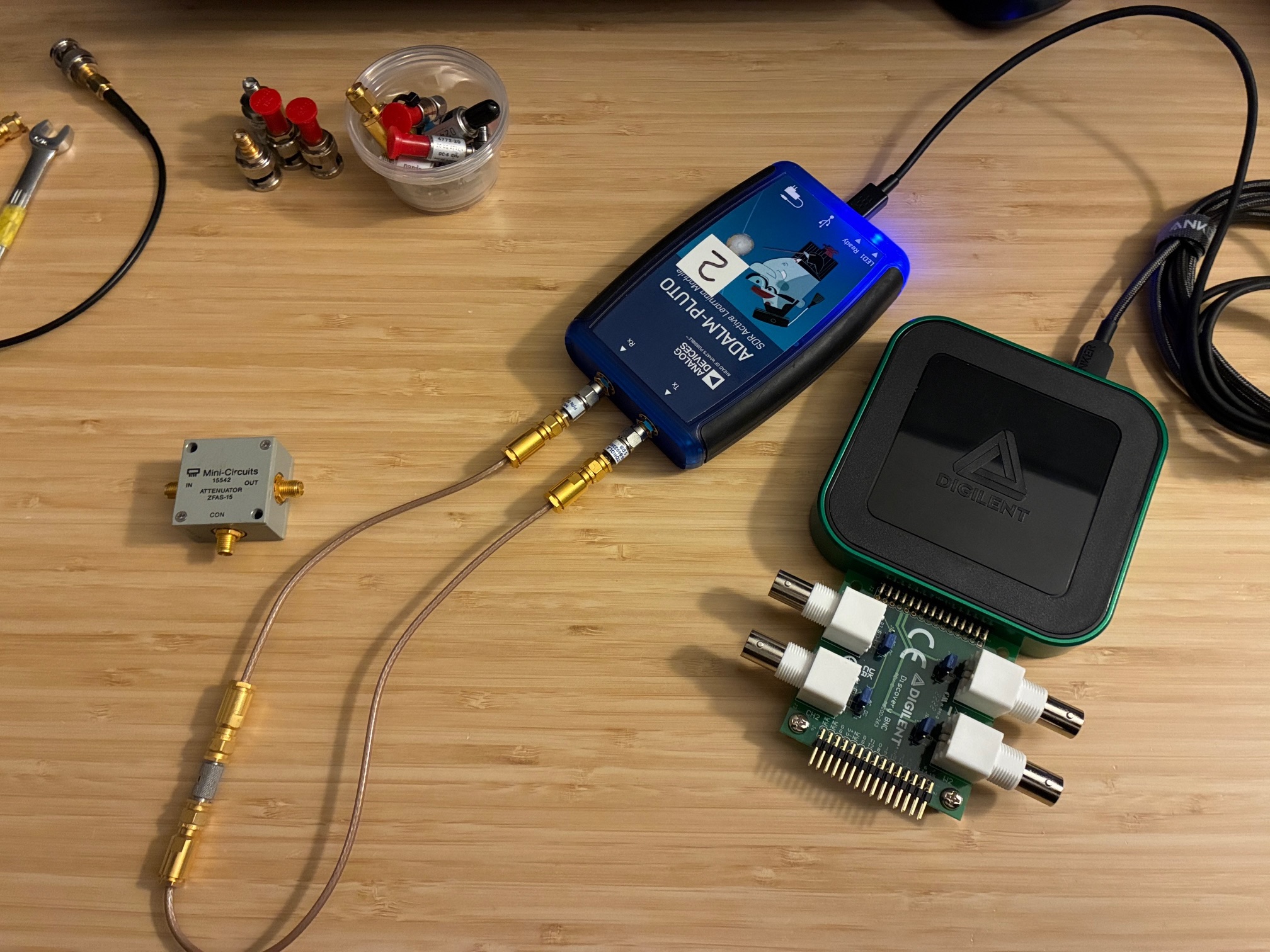
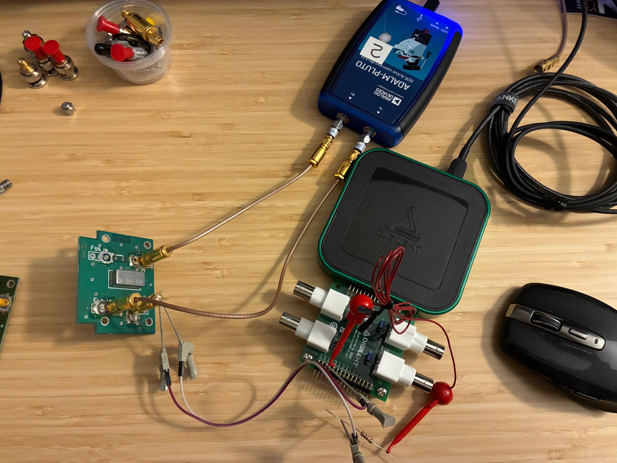
We'll use the ADALM-Pluto SDR controlled by SATSAGEN to generate the test RF signal and monitor the resultant attenuated signal level. A Digilent Analog Discovery 3 module with breakout board will be used to inject DC bias into the ZFAS-15 device. Digilent Waveforms control software will be used to control the output voltage (no LabVIEW today as this is a quick, one-time test).
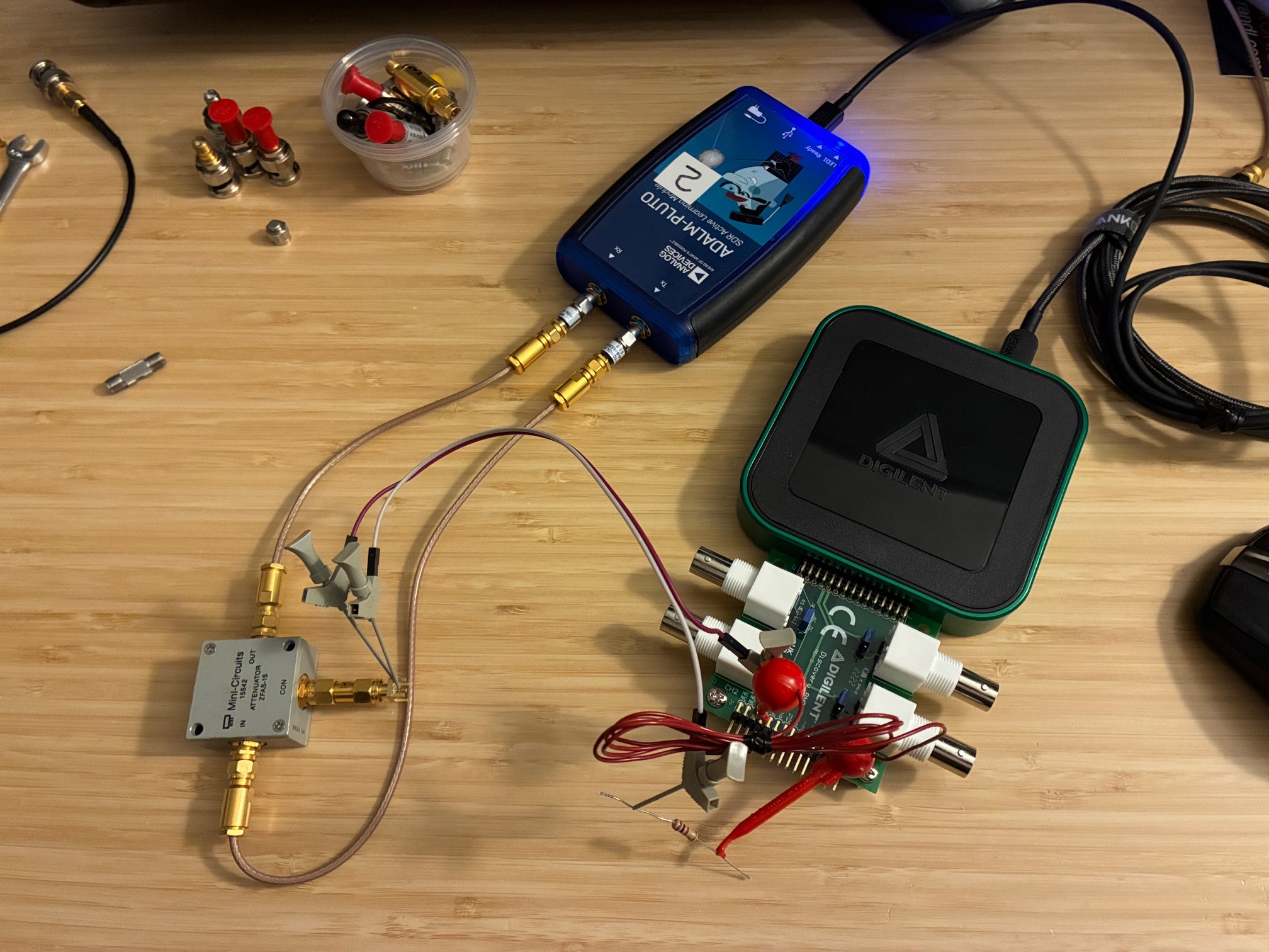
After RF path through calibration (zero), ZFAS--15 is inserted and wires attached from the control port to the AD-3 DC control lines (using a series 1 Kohm resistor for current limiting).
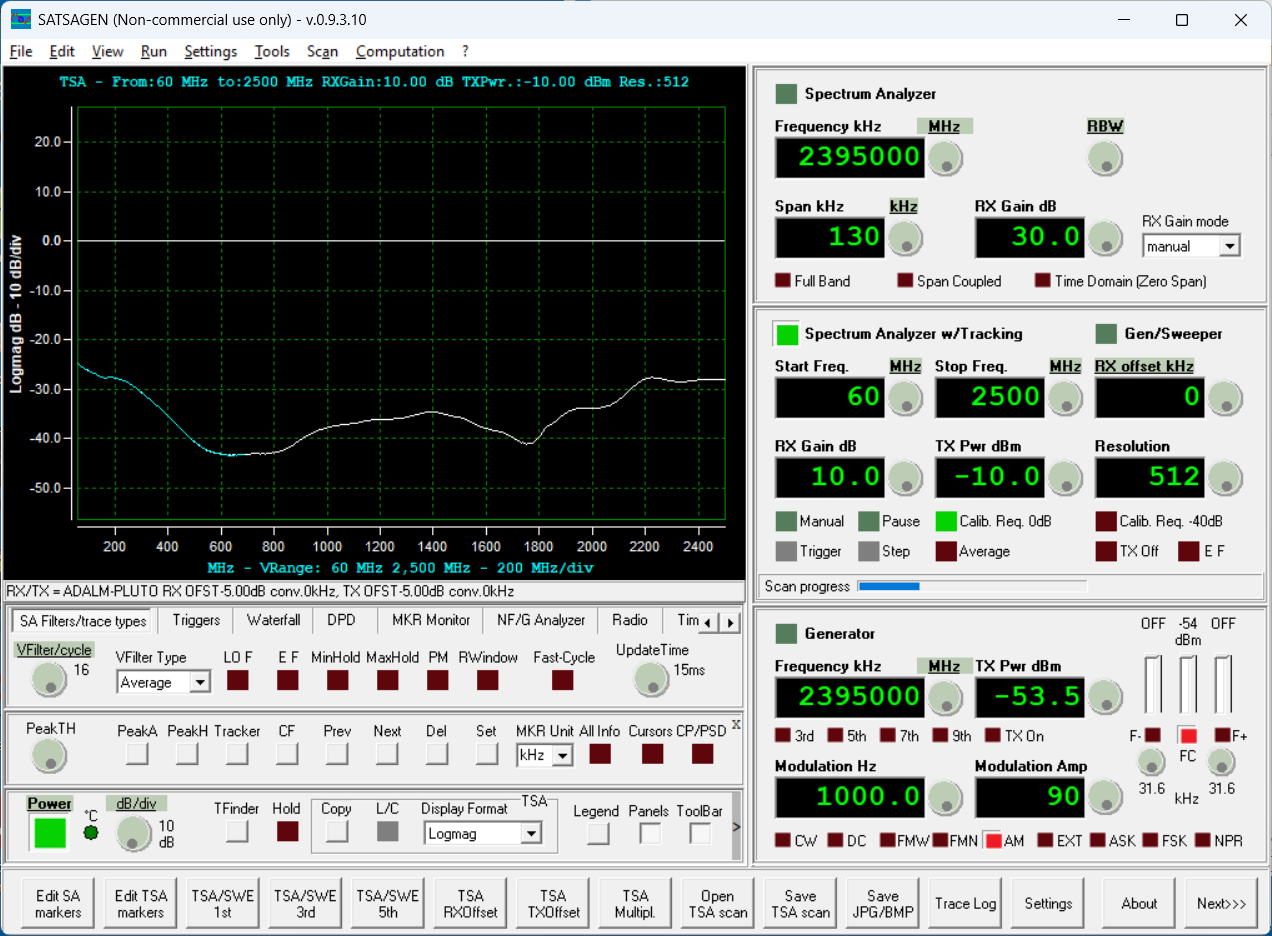
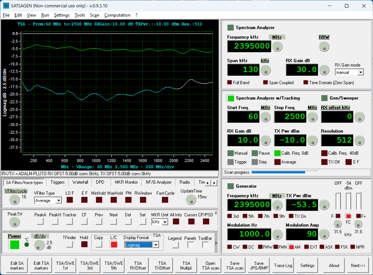
Ready to test - starting with the power off insertion loss measurement. The Pluto SDR covers down to 60 MHz, so we'll use this as a lower frequency limit. The measured value is expected to be high-attenuation due to all of the diodes being fully off, non-conducting.
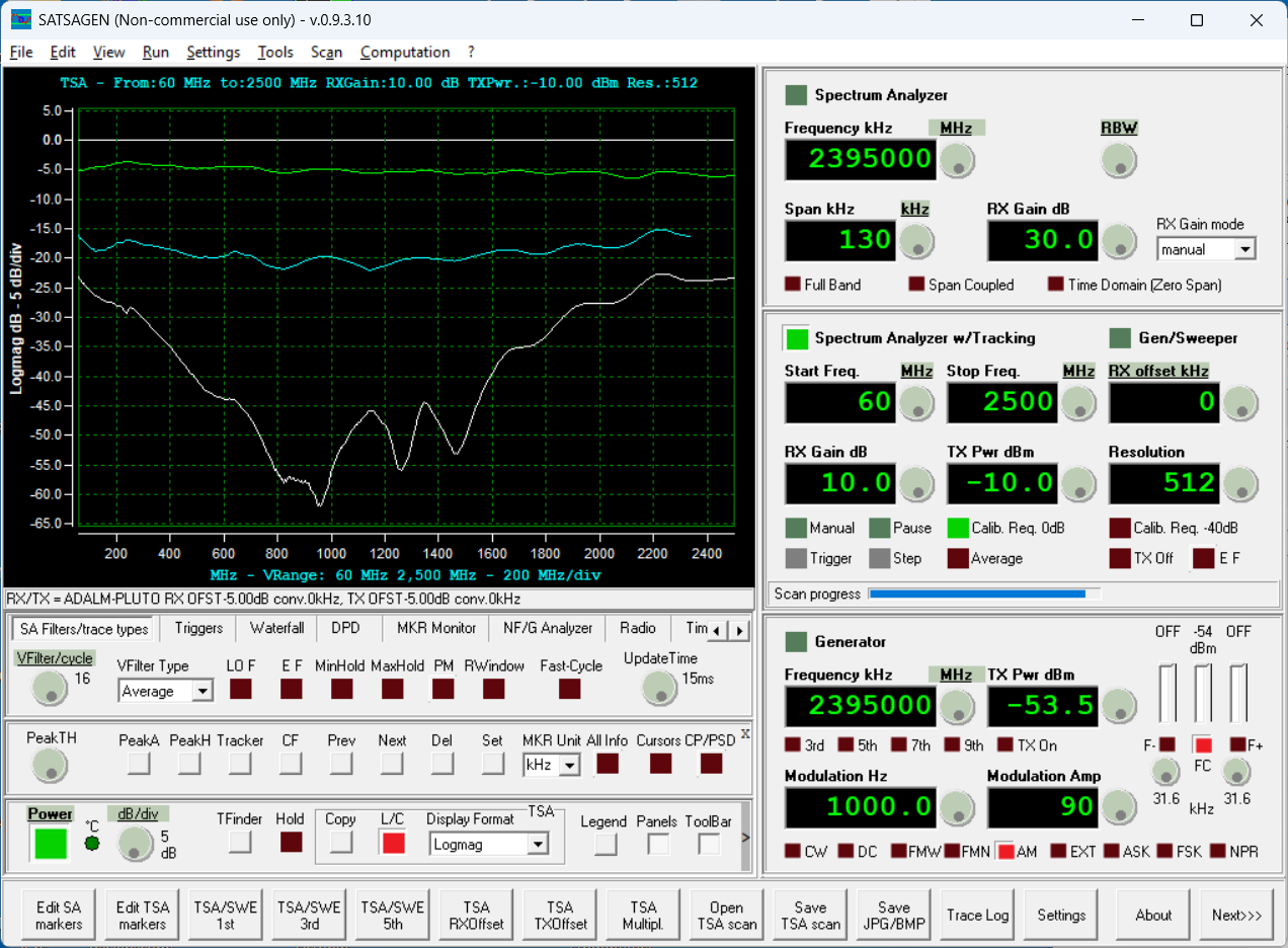
Next the DC supply was turned on, and a value of 1V applied (via the 1K series resistor). The attenuation is expected to decrease.
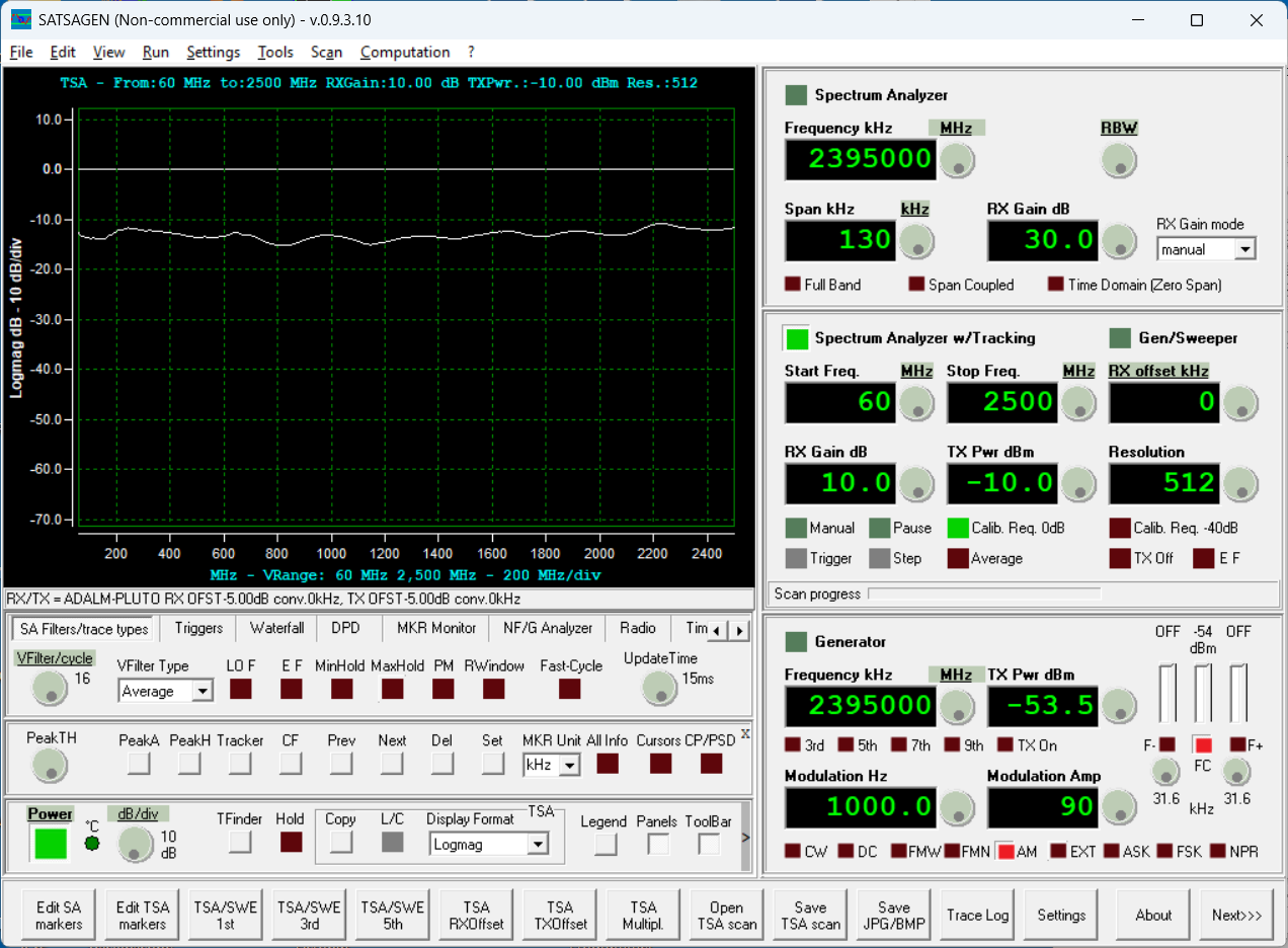
So far, so good. This component appears to be working properly as a DC controlled RF attenuator. Let's set the DC voltage to 2 volts and see if the attenuation decreases further.
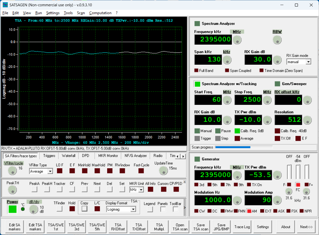
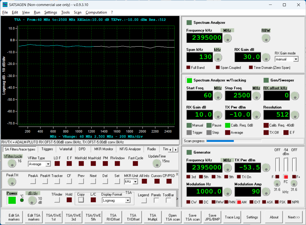
As expected, the attenuation decreased as the applied DC voltage increased. Let's increase the DC voltage to 4V and see if the attenuation decreases further.

The attenuation is approaching the expected nominal insertion loss of the device (~5 dB per the data sheet). The Digilent AD3 can supply up to 5 V DC on the positive supply rail. Setting to that value yields what appears to be a saturated value of the ZFAS-15 control line.
The takeaway so far is that this component provides variable RF attenuation on the through path, with ~5V input providing lowest loss, and ~0V providing maximum loss. The change in DC control voltage is non-linear (in measured dB RF level) and has ripple (amplitude variation) in the passband value verses frequency.
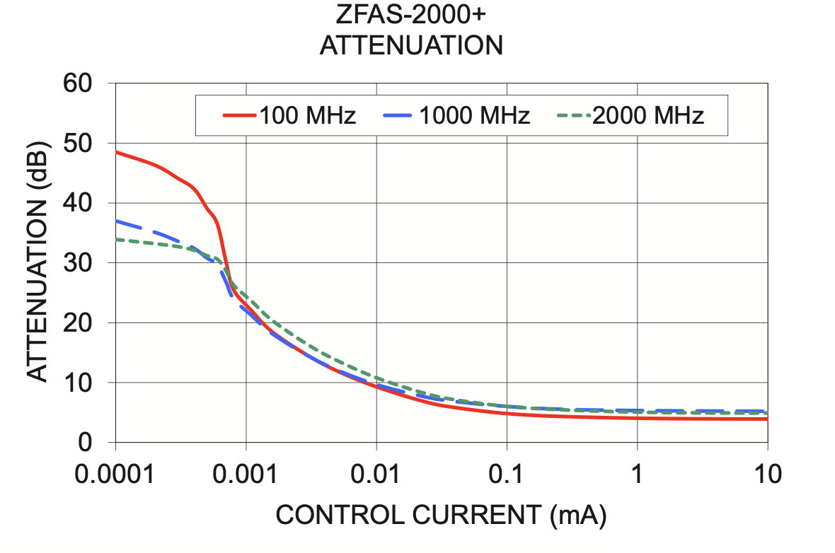
Below is an attenuation verses injected current level for three frequencies. We're using a variable voltage supply with a series 1 Kohm resistor into the control line and are seeing similar non-linear curves over the tested frequency range of 60 to 2500 MHz. For the ZFAS-2000 device, the three curves are reasonably close together over a 25 dB range of attenuation control. The above power-off plot shows similar variance over frequency as the Mini-Circuit chart below indicates.
Let's zoom in a little on the amplitude scale and take a closer look at how the amplitude varies with applied DC control voltage.
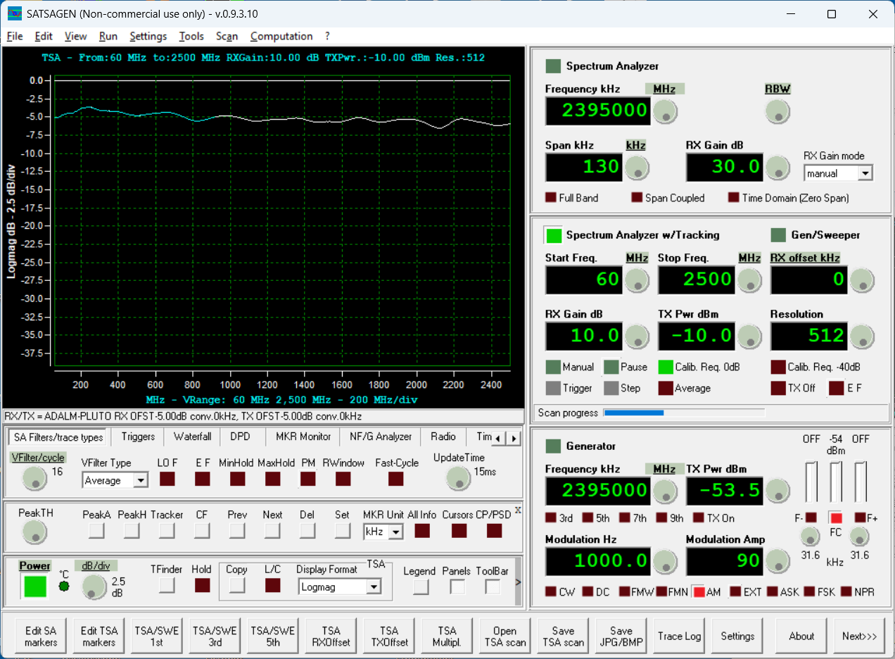
The flatness is not too bad (given the ultra-low-cost nature of the setup and the age of this component). Let's see if we can determine a difference between 5V and 4V control voltage input level. For the graph below, the green upper trace is 5V and the trace approximately 1 dB below is with 4V applied.
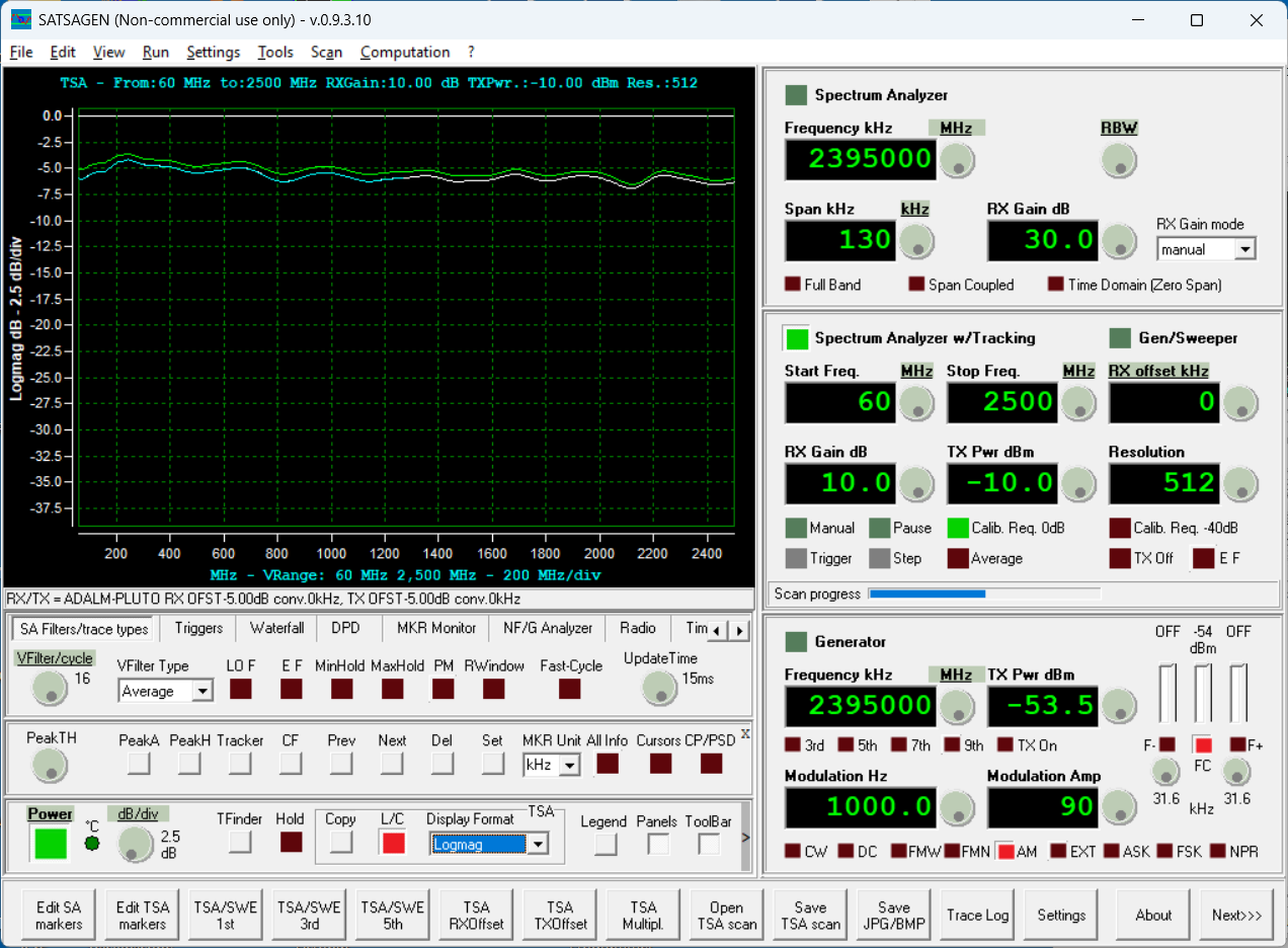
For the graph below, the green upper trace is 5V and the trace approximately 1 dB below is with 3V applied. The insertion loss increased as expected as the control voltage was reduced.
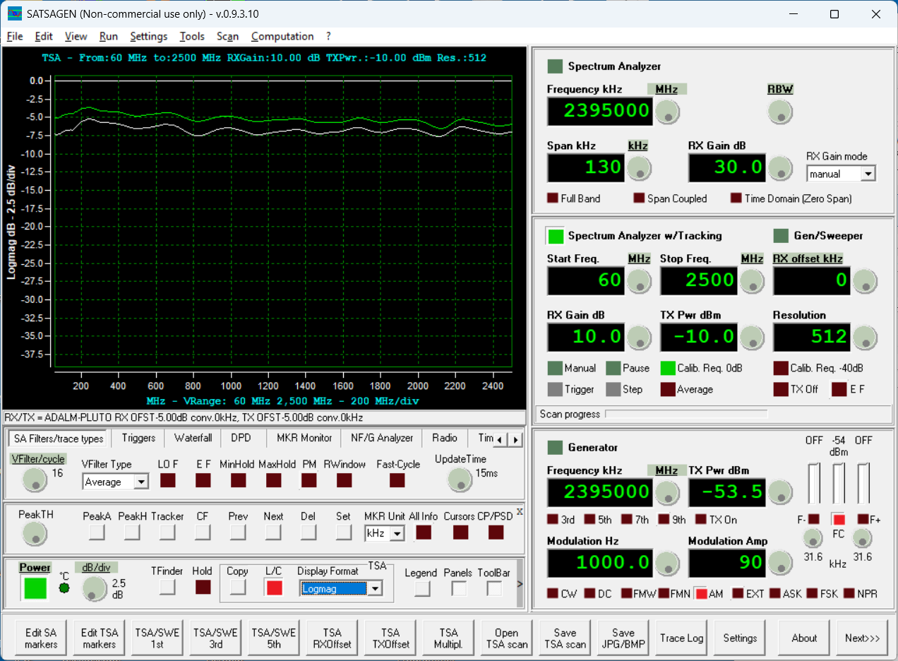
The 5V trace is in green, the trace below is for 2V. Still decreasing level (increasing attenuation) with decreasing control voltage.

Set the control voltage to 1V and managed to capture 5V, 2V, and 1V traces at once.

This pretty well illustrates how this component works, and the amount of attenuation expected verses a 0-5V control voltage input.
As a last test, the control voltage was set to 0.5V. The 5V green trace and the trace below show the total control range of the device.
The second component was tested with similar results. But the question remains, could we just do this with a standard double-balanced RF mixer (like the SBL-1X)? Since we're all set up here, let's test a RF mixer to see if it behaves similarly.
A SBL-1X mounted onto a breakout board was put into the test setup.
Below shows green 5v, blue 0.5v and white supply off.
As guessed, the common COTS RF mixer indeed provides analog DC voltage control over the through path RF signal. Yes, it is pretty non-linear and has ripple over the frequency band tested, but it works similar to the ZFAS-2000 RF attenuator product.
This functionality is limited compared to today's "modern" digital RF attenuators, but does provide simplified RF level control compared to using a digital implementation.
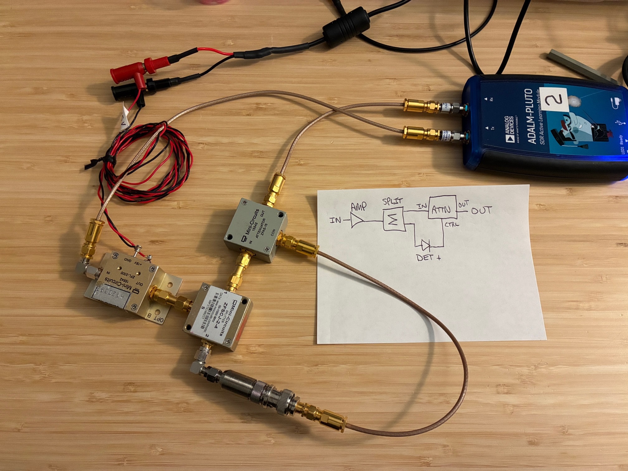
Applications/Use: As an example, a simple RF amplitude leveling loop could be put together (without a microprocessor or other digital control) using the following components:
- RF amplifier
- RF splitter
- RF detector
- ZFAS-2000 or ZFAS-15 component
- A simple inverting amplifier (transistor or op-amp) as needed
- Simple R/C components would set the response speed of the leveling loop to match the application (as needed)
Two (of many) possible configurations are shown below.
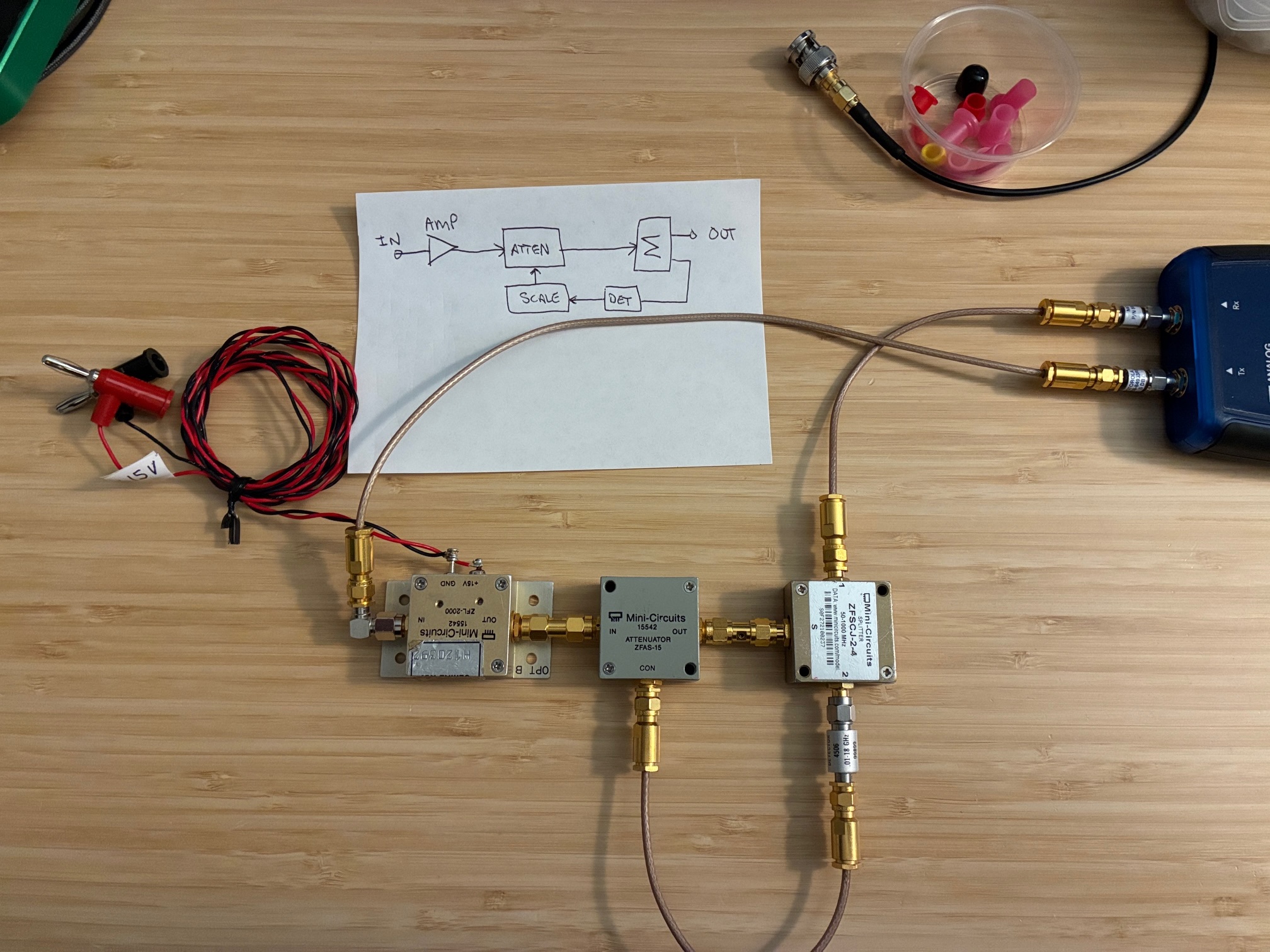
Did not have time to explore these other than a quick setup and test. Neither appeared to work fully as hoped - pointing to the need to have gain or other processing between the detector output and the attenuator control line input. Will be fun to setup and explore further in the future.
Activity Summary: This concludes this test to verify functionality of the Mini-Circuits ZFAS-15 analog RF attenuators. Both devices work properly and now have a Tested/Date label on their package.
Open question / Next steps: Do the ZFAS-15 function reasonably as RF mixers (similar to the SBL-1X)? Will try to remember to test these in the future when setup for frequency-conversion/mixer tests... << Follow on post available at this link. Will it mix?
All author photos taken with an iPhone 16e.