Hello - Czesc - Hej - Bonjour - Dia Dhuit - Kon'nichiwa - Koa - Hola - sawubona - Ciao
After I built the Boom Mic & Shock Mount from my Heil-ICM microphone and using it with the VOX function on the IC-7300. I decided that VOX wasn't for me.
Quite often during the day I park on a frequency, usually 28.490Mhz, an listen for stations. It's a good way to break the day up with a random chat with other operators also working from home. Unfortunately, the VOX can trigger when I get a phone call or when someone walks into the room.
So I decided to make a Simple Foot Switch from bits I collected over the years that were laying around the workshop unloved and unused.
Parts List
1 x Teflon Chopping Board - Free (Off Cuts from the Prototype Vertical Antenna - Kmart).
1 x 90mm Single Loose Pin Radius Butt Hinge - $1.91 (Bunnings Hardware).
1 x M6 x 20mm zinc plated round head bolts, nuts & spring washers - $3.56 (Pack of 8 from Bunnings Hardware).
2 x M6 x 60mm stainless steel hex head bolts, nuts &; spring washers - $6.50 (Pack of 6 from Bunnings Hardware).
1 x 8.0 x 50.8mm compression spring - $4.03 (Pack of 2 from Bunnings Hardware).
1 x Snap-acting momentary micro switch - Free (Local reclamation yard).
1 x Bolts for your momentary micro switch these will depend on your switch.
1 x 2 Core Screened Professional Microphone Cable - $2.85 per meter (Jaycar Electronics).
1 x 6mm stereo male plug - $2.95 (Jaycar Electronics).
Pricing is correct 2020.
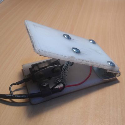
|
Foot Switch Left Side. |
Tools Needed
Flat blade screwdriver.
Phillips head screwdriver.
Small open ended spanner or shifter to suit nuts.
Hack Saw.
Electric hand drill.
6mm drill bit.
12mm drill bit or counter sink tool.
Side cutters.
Smooth file.
Fine sand paper.
Pencil or fine marking pen.
Ruler or tape measure.
Soldering Iron and Solder.
Heat Shrink.
Multi-meter.
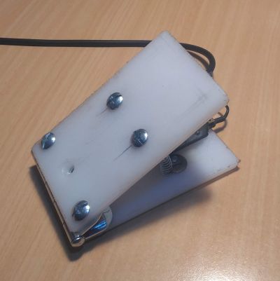
|
Foot Switch Right Side. |
Safety First
I know you will do this, but I'll say it anyway.
Make sure you wear Personal Protective Equipment (PPE) while constructing this project. Steel cap boots, safety glasses, hearing protection and long sleeve shirt and pants may seem like over kill, but when you get a bit of swarf in your eye or drop something on your foot, you'll wish you'd have taken precautions.
Step By Step
Cut the chopping board to size. I made mine 150mm x 100mm each. But you can make then what ever you like. You will need two the same.
Line up and mark the hole centres for the hinges along the short ends of the two chopping boards, ensuring the ball of the hinge is facing away from the cutting board. It will foul if you install the hinge the other way around.
Four bolts will be used to hold the springs in place two on each piece of Teflon. The position of these bolts will require a bit of trial and error. I put mine in 70mm (2-3/4”) in from the hinged end and 20mm (3/4”) in from the edges. Mark the hole positions.
Position the body of the momentary micro switch so it disengages when the foot pedal is in the up position and mark the hole centres.
Drill the four M6 holes for the M6 bolts that will hold the hinge in place
Drill the four M6 holes for the spring retaining bolts.
Drill the mounting holes for the momentary micro switch.
Use the 12mm drill to removed the ragged edges from the holes.
Lightly sand or file back the ragged edges on the chopping broads.
Solder the 2 core screened wire to the 6mm stereo plug ensuring there are no electrical shorts. It doesn't matter which wire goes where because you are only closing the contact to to switch the radio to transmit
Solder the other ends of the 2 core cable to the momentary micro switch. Note that the switch will have Normally Open (NO) and Normally Closed (NC) and a common connection points. Use your multi-metre to determine the NO position as this is the one you need to use. Insulate any soldered bare metal with heat shrink.
Assemble the hinge on to the two chopping boards and trim the bolt threads back if required so that the bolts don't prevent the momentary micro switch from closing.
Install the four bolts for the spring retainers. These can be left long because if they are too short the spring will not be retained correctly and may come out when in use.
Install the momentary micro switch. You might like to fashion a restraining clip for the cable so it does not break the wires when the foot switch is in use. You may need an additional hole and bolt for this if you can not use an existing bolt from the momentary micro switch.
Install the springs.
That's it you're done.
Some Observations
This is a cheap and nasty build.
The Foot Switch is not pretty to look at by any means, but its functional and its under the bench out of sight. So who cares what it looks like.
Even though I'm using shielded cable, I get some RF into the system on 40m. This is antenna specific and not related to the switch itself.
Now, pull up a pew, fire up the radio and go chase some DX.
Cheers