Hello - Czesc - Hej - Bonjour - Dia Dhuit - Kon'nichiwa - Koa - Hola - sawubona - Ciao
Preamble
I'd been using my Prototype HF Multi-Band 1/4 Wave Vertical for around 12 months, and for the most part it worked well. So well in fact that I got lazy and didn't progress it any further than the basic principle.
That changed in January 2021 when we had a series of severe thunderstorms come through Brisbane. I lost 40m and then 30m and eventually the antenna became unusable. I'd already started to collect the various bits and pieces for a the new improved version of my multiband antenna, so the time off air was less than a few weeks during the rebuild.
One of the problems with the previous version was that it was very unwieldy at 12m (40 feet) long with the largest diameter aluminium tube being 32mm (1-1/4 inch). It needed two people to lift it into place. One to do the lifting the other to anchor the base and even then it was like a pace of wet spaghetti.
I decided I need a tilt base to make maintenance and tuning a one person affair. DX engineering sell one, but with the delays in shipping due to Covid and the lousy exchange rate between Green Back and the Aussie, I decide to make my own.
There is no accuracy in this build. In fact it was made completely on the fly. It works for me and if this article gives you an idea or two on how to make your own tilt base, then I've succeeded in helping someone out.
There is a build video at the bottom of this page if you don't like reading.
|
Parts Inventory. |
Parts List
NOTE. The "Stauff" clamps used are to suit a 50mm (2 inch) diameter aluminium tube. Your mileage may vary
0.6m (24 inches) length of 100mm (4 inch) structural aluminium channel with a minimum wall thickness of 8mm (5/16 inch) - $21.50 (Alsun Aluminium).
0.5m (18 inches) length of 125mm (5 inch) structural aluminium channel with a minimum wall thickness of 8mm (5/16 inch) - $31.50 (Alsun Aluminium).
2 x 150mm (6 inch) M10 stainless steel hex bolts - $2.00 (Nut & Bolt Supply).
4 x M10 stainless steel flat washers - $0.50 (Nut & Bolt Supply).
2 x M10 stainless steel spring washers - $0.20 (Nut & Bolt Supply).
4 x 75mm (3 inch) M6 stainless steel hex bolts - $1.00 (Nut & Bolt Supply).
2 x 50mm (2 inch) ribbed hydraulic "Stauff" clamp complete with threaded support plate - $10.00 (Industrial Hydraulics).
2 x 50mm (2 inch) Antsig 8mm U-Bolt & V-Block Clamp Antenna Accessory $17.72 (Bunnings Hardware).
1 x 150mm (6 inch) Taskmaster 7.8 x 150mm 316 Stainless Steel Eye Bolt $5.67 (Bunnings Hardware).
1 x 500mm (20 inch) Zenith 2mm Zinc Plated Double Jack Chain $1.00 (Mitre10 Hardware).
Pricing is correct 2021.
|
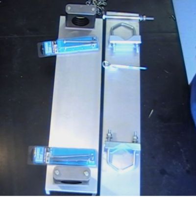
Completed Tilt Base. |
Tools Needed
Spanners and sockets to suit suit bolts and nuts nuts.
Hack Saw (or angle grinder or cut off wheel).
Electric hand drill.
4mm pilot drill bit.
7mm drill bit.
9mm drill bit.
11mm drill bit.
16mm drill bit or counter sink tool.
Smooth file.
Pencil or fine marking pen.
Ruler and/ or tape measure.
Centre punch.
Ball peen hammer.
Pliers.
Safety First
I know you will do this, but I'll say it anyway.
Make sure you wear Personal Protective Equipment (PPE) while constructing this project. Steel cap boots, safety glasses, hearing protection and long sleeve shirt and pants may seem like over kill, but when you get a bit of swarf in your eye or drop something on your foot, you'll wish you'd have taken precautions.
|
Completed Tilt Base. |
Step By Step
Seat the 100mm (4 inch) channel inside the 125mm (6 inch) channel and align one end. Note that the channels should be different lengths.
Mark the both legs of the longer 100mm (4 inch) channel down to the base.
Remove Both legs of the channel down the base ensuring the base is not scored by your chosen cutting tool.
File or grind the ragged edge so the legs finish completely flush with the base of the channel.
Remove all sharp edges with a file
Mark and centre punch the centres for the M10 bolts in each end and both sides of the 125mm (6 inch) channel. I came in around 30mm from the end and centred of the channel leg.
Drill pilot holes in the 125mm (6 inch) channel using the 4mm drill bit in the marked locations.
Drill out the holes with 11mm drill bit & clean up the holes with the 16mm drill bit. This can be done by hand.
Insert the 100mm (4 inch) channel into the 125mm (6 inch) channel and mark the location of the corresponding holes. Ensure the channel is aligned correctly or your holes will be skew-iff.
Mark one end of each channel so you don't inadvertently flip them around and end up with misaligned holes.
Drill pilot holes in the 100mm (4 inch) channel using the 4mm drill bit in the marked locations.
Drill out the holes with 11mm drill bit & clean up the holes with the 16mm drill bit. This can be done by hand.
Round off the corners of the 100mm (4 inch) channel legs to allow the hinge to swing unimpeded. You will need to test fit and use trial and error to determine how much material to remove.
So that the hinge opens a full 90 degrees you will need to remove around 10mm (3/8 inch) of material from the bottom end of the 125mm (6 inch) channel.
Test fit to make sure it all works
On the 100mm (4 inch) channel, mark the hole centres for the U-Bolt & V-Block Clamps. I came in about 50mm (2 inches) from the top and about 150mm (6 inches) from the bottom... about 50mm (2 inches) up from where the 125mm (6 inch) channel finishes.
On the 125mm (6 inch) channel mark a centre line for your hydraulic clamps
Find the centre point of the hydraulic clamp plate and mark it
Ensure that you align the hydraulic clamp plate holes in a way that the clamp bolts do not clash with the U-Bolt & V-Block Clamp bolts.
Mark the locations for the hydraulic clamp holes and centre punch their locations.
Drill pilot holes in the 125mm (6 inch) using the 4mm drill bit in the marked locations.
Drill out the holes with 7mm drill bit & clean up the holes with the 16mm drill bit. This can be done by hand.
Assemble the tilt base and test to ensure nothing clashes and it all works as intended.
Mark a location for the safety pin at the top of the tilt base. I recommend about 75mm (3 inches) down for the top so it misses the hydraulic clamp and U-Bolt & V-Block Clamp bolts.
Drill pilot holes through both legs of both channels, ensuring they are in line.
21. Drill out the holes with 9mm drill bit & clean up the holes with the 16mm drill bit. This can be done by hand.
Thread the chain through the eye of the eye bolt and secure. You will need to prise open the link with pliers or some similar tool and then close it up again around the eye bolt.
The other end of the chain can be retained by the top U-Bolt.
That's it you're done.
ADDENDUM: Base Plate and Mounting Description
I had a question from Cliff W4CBH on the YouTube video I put up shown the tilt base in action.
Cliff Wrote...
Great job my question is your base mount how large is the pipe and deep and how large to the hole. thanks Cliff W4CBH.
My response below in full...
Hi Cliff, thanks for stopping by and commenting.
Long answer for a short question because the base plate is not well described or shown in the video(s).
The base plate is made form some scrap aluminium about 225mm (9 inch) square and 6mm (1/4 inch) thick. I drilled and tapped 8 x M8 (5/16 inch) threads into the plate and used stainless steel M8 hex bolts to secure the 32 ground radials 5m (16 feet) long each. This means I can have everything in place and attached the radials from the top of the base plate with a ratchet and socket.
It also eliminates two things:
Having to somehow tighten a nut on the underside of the plate (which could work loose) and,
If the nut was on top of the plate, prevents bolt protrusions catching on your toe or mower or weed wacker. The way I have it, there are not protrusions only the head of the bolt is visible.
The base plate is electrically connected (bolted) to the tilt mechanism with a 40mm x 40mm 1.6mm (1-1/2 inch x 1-1/2 inch x 1/16 inch) angle and stainless steel M8 bolts. The angle sticks out one side just enough to hold an SO-239 panel mount. The angle does not have to be strong, its only for the electrical connection and SO-239.
This method ensures the coax braid is completely earthed to the radials and the post in the ground via the SO-239 and the centre pin simply goes to the radiating element via a 100mm to 150mm (4 inch to 6 inch) long fly lead. I used 2.5mm (#14) house type earth wire for this. The benefit of the SO-239 is that you can disconnect the coax when you mow.
One thing. Make sure you sand or file off any anodising from the aluminium so it creates a better electrical connection where the bolts and clamps connect.
The hole in the base plate is 60mm (2-3/8 inch) diameter cut with a hole saw, its just big enough to take the 40 x 40 (1-1/2 inch x 3/16 inch) SHS (Square Hollow Section). You could use 4 corner holes and a hacksaw to make a square hole if you do not have a hole saw.
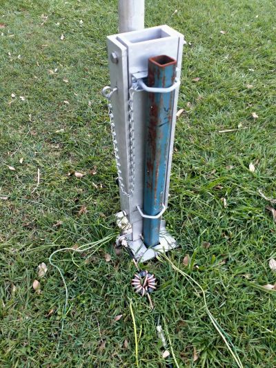
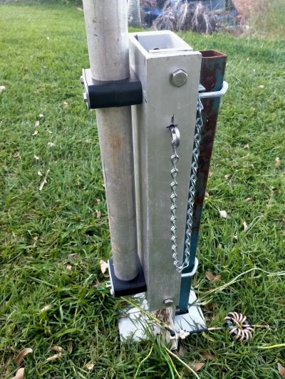
The SHS post is about 1.8m (6 feet) into the ground; no concrete, and about 500mm (20 inch) above ground. This also helps with the earthing as its clamped to the tilt mechanism.
You could make the post shallower or deeper but it will depend on your ground conditions. I have soft ground here and decided to to put some 4mm (1/8 inch) paracord guys to help stabilise it a bit in the wind. The antenna will stand by itself without issue without them though.
Do not forget to watch the construction video if you have not already seen it. There is also a write up with a complete list of parts of the tilt base on my web page https://...
Cheers
Some Observations
I used a 2.0m (78 inch) length of 4mm thick wall 50 (2 inch) SHS steel for my support post. It is 600mm (24 inches) above ground and about 1800mm (70 inches) in the ground. I did not use cement as I didn't think it necessary.
I have had this base in service on a 40m 1/4 wave vertical for a few months and it has stood up to some pretty strong wind storms without even looking like coming down or working loose. You may choose to do otherwise.
Now, pull up a pew, fire up the radio and go chase some DX.
Cheers