
Introduction
Pulsar were a well-known lighting controller manufacturer founded, I believe, in the late 60s, and through the 70s & 80s their products were used by many of the mobile discos doing the rounds at that time, including mine. Later known as Pulsar Light of Cambridge Limited, the company sadly went into administration in March 2017, finally being dissolved in December 2018.
Pulsar produced a wide range of products, but one of the most popular had to be the little Zero 2250; this was a very basic 3-channel sound to light controller, with each channel rated at a maximum of 750 watts, hence the '2250' designation. The 'zero' part of the name references the 'zero voltage switching' feature, whereby the triacs are switched close to the point where the mains voltage crosses the zero voltage point (the start of quadrants I & III), extending lamp life but more importantly practically eliminating radio interference.
Pulsar's SL Super Mk.2 and FAL's Automatic Rhythmlight also used the same circuit board as the Zero 2250, so the information I've put here can also apply to them. The Pulsar Zero 3000 was a similar unit but offered a lot more features so they were considerably more expensive with the 3000 selling for over twice the price of the Zero 2250, and it used different electronics internally.

Pulsar Zero 2250 advert from the 1979/1980 Squire's catalogue
Pulsar kept the price of the Zero 2250 reasonable by cutting out all unnecessary fluff, creating a 'bare bones' design; it had just a jack socket for the audio input, an 8-way Bulgin PX0552 socket for the power output to the lights (taking the PX0551 plug) and of course a mains lead. There were no adjustments to fiddle with, as the unit incorporated an automatic level control for each of the 3 channels making it pretty much a 'fit and forget' unit.
The circuitry was simple but ingenious, using the minimum component count to get a fairly complicated job done; no firmware or software was used as seems to be the norm these days, it simply worked immediately when plugged in, with no fuss or drama.

Bulgin socket pin numbering
All this functionality was neatly boxed up in a tough metal case just 14cm square, capable of surviving life on the road which in most cases probably meant plugging in the various leads and tossing the unit on the floor out of the way. The combination of sensible pricing, toughness and reliability were no doubt responsible for the unit being so popular; for reference, a Pulsar Zero 2250 would have cost you around £46 back in 1980, according to a Roger Squires price list from the time.
These units were built to last and as a result many of these controllers are still kicking around, but because they weren't overly expensive to buy, if a fault eventually developed, they'd end up in the bin rather than being considered worthy of repair. This page outlines some basic modifications and maintenance to the Zero 2250 which will ensure these iconic little controllers will continue to function for decades to come, whether powering the lighting for a retro-style disco or just hypnotising the grandkids.
For the latter I recommend two horizontal banks of red, green & blue coloured lamps, wired as mirror images of each other; with some dancy music playing, they'll stare at the lights for ages!
The electronics of these lighting controllers didn't have to remain in their little metal boxes; I removed the circuit board of one of my Pulsar Zero 2250 controllers from its enclosure and created a bespoke light control unit by fitting it in another, larger box along with a 4 channel sequencer, with enough output sockets on the back to allow my various light boxes to be connected.
Rather than using the PA amplifier's output to drive the 2250 which was awkward with Speakon connectors, I used the mixer's 'booth' output. The signal level of this output wasn't enough to properly drive the 2250 directly, so included in the box was a small 5 watt chip amplifier, the output of which was fed to the controller. The system worked very well and was used for over 25 years to power my front light boxes, right up to when I ceased mobile disco operations in 2012.
For information, rather than constructing a complete chip amplifier as I did originally, a small amplifier circuit using one 741 op-amp as shown here does the same job, but is much simpler and smaller. A signal voltage of just 2 volts peak to peak fed into the 2250's high-impedance audio isolating transformer seems to be enough to flash the lights, although I'd recommend double this to be sure; the 741 can supply around 20mA of current, which is more than enough for this application and with a ±15 volt supply, can output around 12 volts peak to peak with the frequency response flat to around 13KHz, more than enough for this job.
I built the circuit shown and now use this instead of the old system of using an amplifier chip. The voltage gain was measured at around 17 times with the values shown, exactly what the calculations predicted.
If there is no way of controlling the level of the incoming signal, a volume control should be included at the input to ensure the circuit isn't overdriven to a silly degree, although hi-fi quality certainly isn't required here. As the output stage of the 741 is a complementary pair, it can be connected directly to the 2250 with no capacitor needed.
Inside the Pulsar Zero 2250
The photos below show the complete Zero 2250 control unit, and what it looks like inside with the top panel unscrewed and inverted. As can be seen, all the instructions anyone could want are printed on the top of the unit for convenience.

The Pulsar Zero 2250 |
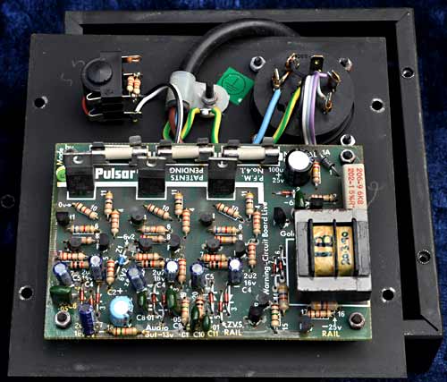
Inside the Zero 2250 |
Bolted to the underside of the top panel is the circuit board; a prominent component on the board is the audio isolation transformer, essential for isolating an amplifier from the controller's electronics, which are live and at mains potential.
There are also the three triacs (type TIC246D in one of my units and BTA12-600C in the others), with their associated 5 amp fuses. Triacs are pretty tough components and difficult to destroy, so as long as the unit hasn't been badly abused, short-circuited or sworn at too much, they should be in working order.
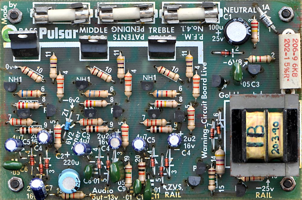
Close-up of a Pulsar Zero 2250's circuit board
The triacs aren't fitted with heat sinks, and don't really need them unless you intend to operate the unit at full capacity, in which case a small heatsink on each device will help keep temperatures down. When a channel is connected to a 100 watt load, its triac runs completely cold; at 300 watts, slightly above ambient and with a 750 watt load, around 50°C. Bear in mind that any particular triac is conducting for less than 50% of the time so has a low duty cycle anyway, helping to keep heat generation down.
Using LED Lamp Replacements
Something to consider in our modern LED-ridden society is that the Pulsar Zero 2250 controller needs a minimum resistive load equivalent to around 100 watts on each channel (depending on the triacs used) to reliably switch on both positive and negative parts of the mains waveform; 40 watts probably won't be enough, with the triacs delivering only a half-wave output, if they trigger at all.
This is the nature of triacs, as they need to be passing a sufficient 'holding current' to remain on once triggered, the current required being generally higher in one polarity than the other. Note that this minimum holding current requirement has to be met when the mains voltage has just passed the zero voltage point and therefore the voltage being fed to the load, at that moment, is small. If using LED lights alone, this will probably be too light a load and the minimum holding current won't be achieved; the lights probably won't flash and the controller will appear to be faulty.
The minimum load issue can be worked around by ensuring that one of the lamps on each channel is a 100 watt incandescent type, or you could connect a pair of 220Ω, 50 watt aluminium-clad resistors in series to make 440Ω, then connect one of those resistor pairs across each of the controller's outputs to provide the minimum required resistive load. If you do this, be sure to provide a large heat sink for the resistors and to allow for the substantial amount of heat they'll generate.
Another Problem, And How To Deal With It
Even if you do work around the minimum load issue, many LED lamps won't tolerate the rapid on-off cycles and could prematurely fail unless you protect them in some way.
A simple and effective way to stop LED lamps from failing due to repeated inrush current is to incorporate a series resistance. Some higher wattage LED lamps don't work properly with any significant series resistance due to the nature of their internal circuitry, and may exhibit odd unstable behaviour.
However, if you choose a lower wattage version, say 3 or 5 watts, there's a chance that the circuitry will be a lot simpler and consist essentially of a capacitive voltage dropper and rectifier. This type of lamp will continue to work well with a surprisingly large series resistance, albeit with a correspondingly lower light output; with a suitably high value resistor in series, the life expectancy of these lamps can be dramatically extended to the point where they'll probably outlive you.

The Pifco lamp referred to in the text
I've spent quite some time experimenting using LED lamp replacements with the Pulsar Zero 2250 and there's one LED lamp in particular that I've found to be particularly suitable, and these are the little 3 and 5 watt jobs marketed under the Pifco name. Not all Pifco lamps are the same, but these particular lamps can be identified by the slots around the plastic body, these using a capacitive voltage dropper; for how long these particular lamps will continue to be available is unknown, but supply was getting patchy in 2026.
These lamps are available in 'cool white' 6500k which is excellent if you are going to have a green, blue or purple filter gel over them, and 'warm white' 3000k which is best if you are using a red, orange or yellow filter.
They are available in ES and BC fittings, but what's best about these little lamps is that you can (and should) use quite a high value of resistor in series to reduce heat generation within the lamp; I found that they give a reasonable although obviously much reduced output with a resistance as high as 100KΩ in series, and with a high enough resistance such as 470KΩ in series, can be dimmed right down to a slight glow for use as a night light, making them very versatile lamps.
Note that the 5-watt version is somewhat over-run when connected directly to the mains and will therefore have the relatively short life typical of most LED lamps unless you limit the light output; it does, however, have ten LED chips in it rather than just five as the 3-watt version does, and as such, is the better buy if you plan to put a limiting resistance in place as you'll get better efficiency and for a given light output, each LED chip is running at half intensity.
For the 240-volt 5-watt Pifco lamps, I recommend a series resistance of around 6·8KΩ which not only completely eliminates inrush current, but also reduces the intensity of the lamp somewhat, extending its predicted lifespan to decades; the LED chips will be running just warm under continuous use and practically cold at typical Zero 2250 duty cycles.
The resistor suggested will dissipate around 1 watt when in series with a 5-watt lamp, so a 2-watt or 3-watt rating would give ample headroom. Although a pure resistance is best for several reasons, a capacitor of a suitable voltage rating could be used instead; for information a 0·47µF capacitor gives a close brightness approximation to that provided by a 6·8KΩ resistor; the value tolerance should be 5% or better, or there may be a discernable difference in brightness between the lamps.
5W LED lamps with series resistances and an optional overall resistance
The limiting resistor (or capacitor) should be fitted in series with each individual lamp; this ensures correct current limiting and current sharing. Another resistance (R adjust) of perhaps a few hundred ohms can be placed in the supply line to allow the brightness of that particular group of lamps to be adjusted down if needed, to compensate for the way different coloured gels affect the apparent brightness, but that's something to experiment with if needed.
If the lamps are going to be behind a diffuser or screen of some sort which would prevent access by inquisitive fingers, you could remove the domed diffuser from the front of the lamp; I find that a sharp knife blade can be used to carefully lever the dome from the body allowing its removal, but be careful not to neuter yourself in the process.
With the diffuser removed, the forward-facing light intensity will increase considerably, allowing you to use a higher series resistance which would put even less load on the LEDs, or you could just enjoy the added brightness. Be aware that with the diffuser dome removed, it will be possible to touch live contacts on the lamp's circuit board, so as with most things in life, be careful where you poke your fingers.
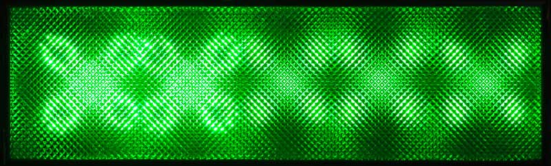
Comparing dimmed 5-watt LED lamps to 40 watt incandescent lamps
The photo above is of one of my light boxes on its side, with the first two lamps being 5-watt LEDs with a 6·8KΩ resistor in series with each one, both having had the domed diffuser removed; the remaining three lamps are 40-watt incandescent types, as would normally have been used. Even with a fairly high resistance in series, the LEDs outshine the old 40-watt lamps by quite a margin, and arguably produce a more interesting pattern on account of the ring of LEDs.
Although messing around with series and load resistances is a bit of a faff, it's an excellent way to convert your classic light panels to LED lamps, and correctly done, it's done for good and you'll never need to change another lamp; the boxes will run cold, apart from the load resistance needed for each channel which could, of course, be built as a separate unit if you wish.
I've been informed that Big Clive has done some experiments with the exact Pifco lamp I've discussed, so the following You Tube videos may be of interest from a technical standpoint:
Big Clive on Pifco lamps part 1
Big Clive on Pifco lamps part 2
Useful Circuit Board Test Points
WARNING!
The circuit board of the Pulsar Zero 2250 is live, so it is vital that the board is powered using an isolation transformer before any test equipment such as an oscilloscope is attached, or severe damage will occur to the board, test equipment or both.
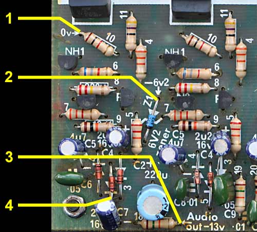
The following test points can provide useful diagnostic information to someone who can interpret the results, but be aware that the board is live and at mains potential. Connections are made to the component leads where indicated.
Test point 1 is the 0 volt rail and connection is made to the lead of the 1kΩ resistor; all other test points are of a negative voltage when referenced to this. Note that this is also the mains live connection.
Test points 1 - 4 |

Test points 5 - 7 |
Test point 2 is where the -6·2 volt rail can be measured, and where the ripple voltage on that rail can be checked.
Test point 3 is where you can examine the amplified version of the logarithmically compressed audio waveform produced by the diodes wired across the isolating transformer. This signal rides on a DC voltage of around -13 volts and should be around 20 volts peak to peak.
Test point 4 is one of the three points where you can monitor the 0·6 volt zero crossing trigger pulses.
Test point 5 is the point where you can verify that the -6·8 volt rail is present and at the correct voltage.
Test point 6 allows you to monitor the compressed and rounded incoming audio signal created by the pair of diodes before any amplification is applied; the waveform should be symmetrical and around 1 volt peak to peak.
Test point 7 is where you can check the level of the -25 volt rail and measure the ripple voltage on it.
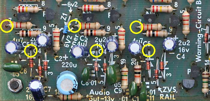
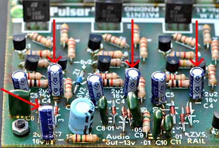
Points where the ALC voltage can be observed
The above three pairs of locations highlighted by the yellow circles are where you can monitor the voltage developed across any of the three 4·7µF capacitors, being between one end of the 3·3KΩ resistor and the diode's lead. Without audio, the voltage should be around 6 volts, rising to between 20 and 30 volts when audio is applied to the unit. This variation is best observed using an oscilloscope set to measure DC.
Suggested Modifications
This section assumes you have adequate soldering skills and have at least a basic understanding of electronics.
Most components on the board operate well below their thermal and electrical limits; this leads to a reliable unit where in general, none of the transistors or small resistors should ever need replacing. There are, however, certain components that do generate heat or can age, so these will be discussed in this section; to help understand the function of the components being discussed, refer to the schematic which can be seen by clicking the link below.
Pulsar Zero 2250 schematic
(Opens in a new tab)
Mains Dropper Resistor R1
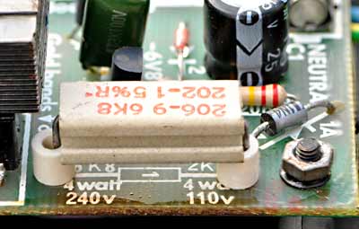
Mains dropper resistor R1
The power supply for the Zero 2250 involves, among other components, a large 6·8KΩ mains dropper resistor, and this tends to run quite hot under normal conditions; it's operated close to its maximum rating, so if your unit isn't working, it would be worth checking that this resistor hasn't failed open-circuit before you venture further with your diagnostics.
This resistor is mounted directly to the circuit board on short leads, and on any well-used unit, the board around it will have discoloured from the heat generated. The heat may well have also compromised nearby components as when the controller is correct side up, the heat from this resistor (which is then on the underside of the board) rises up onto the board.

In my view, this is a bit of a design oversight, so the first step in improving long-term reliability is to move this resistor off-board. I recommend replacing it with an aluminium-cased chassis-mount unit rated at around 10 watts or more, and bolting it to the inside of the metal case which will act as a heat sink, connecting the resistor to the board using adequately long insulated leads. There should be room to fit it to the base directly below where the sockets will be when assembled, but check the clearance.
It is very important to obtain the resistor from a reputable supplier and check in the specifications that it can withstand a kilovolt or two between the element and the earthed case (stated as dielectric strength), or you may experience fizzy, poppy, fuse-blowing problems.
Another point: if you insist on buying components of dubious chinese origin, you'll probably find that their aluminium-cased resistors don't sit well on a flat surface as they tend to be warped, badly extruded and generally of poor quality, possibly using cases rejected by the main manufacturers; on the odd occasion when I have been tempted, the only solution was to 'lap' their bases with wet & dry 400 grit to try to get at least some part of the base flattish. Another question is, who knows what tiny resistive element is fitted inside these supposedly high-wattage resistors? Basically, they are crap; don't waste your money.
Reservoir Capacitor C1
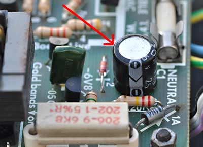
Reservoir capacitor C1
There's an electrolytic capacitor mounted on the board close to where the dropper resistor was fitted, and the heat from the resistor is conducted to the capacitor, making it get quite warm; this would cause it to deteriorate over time. In addition to this, the voltage across it can exceed its 25 volt rating (mine measured 27 volts), so this component is a likely eventual failure point.
The original capacitor was a 100µF 25 volt component, and I replaced it with a 105° 35 volt 680µF unit, as I happened to have some of this value around; with the high temperature rating, I expect it to have a long life, especially as that big hot resistor has now been removed from the board.
The original 100µF value was a bit marginal, but it's worth bearing in mind that these controllers were built to a price, and they'd have used the smallest capacitor they could, consistent with getting the job done. As renovators, we don't have that restriction; as a far larger capacitance can be obtained in the same size package these days, besides a voltage upgrade, we may as well upgrade the capacitance too, as this has the benefit of lowering the ripple voltage being fed to other parts of the circuit.
An annotation to the diagram suggests that the ripple across this capacitor should be less than 600mV; with the larger capacitor I fitted, the ripple measured around 240mV, well below the minimum specified.
Current Limiting Resistor R2
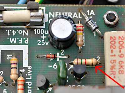
Current limiting resistor R2
Close to dropper resistor R1 is a small 1·5KΩ resistor, R2, providing current limiting for the 6·2 volt Zener Z1 and D2 string. This resistor generates just over 250mW of heat itself, but will certainly have been affected by the heat from the large dropper resistor next to it; the paint on the resistor in one of my units had started to flake off, suggesting it had been running too hot for too long.
This resistor is 'mission-critical', as if it failed, it would cause some exciting and spectacular failures of other components. As a precaution, I replaced it with a 1 watt resistor but left it on longer leads so it sits about 15mm above the board, to ensure that whatever small amount of heat it does generate doesn't get to the board or nearby components, and also ensures a flow of free air around the resistor.
Depending on the condition of the resistor in any particular controller, it may not be strictly necessary to replace it, the one in the unit pictured here for example appearing to be in good condition. However, given the damage that could result if this resistor should fail open-circuit, I would highly recommend that if it shows any signs of having got hot, it is replaced with a higher wattage version.
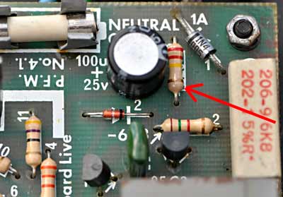
Adding A Protective Zener Diode

Protective Zener soldered in place
The big dropper resistor R1 feeds capacitor C1, and relies on a predictable current draw from the rest of the circuit to keep its voltage from climbing excessively. If the Zener diode current-limiting resistor R2 for example should fail open-circuit, that would allow the voltage across C1 to increase dramatically which could destroy it in exciting style, but more importantly, the resulting over-voltage would be fed to other parts of the board, causing multiple component failures.
Considering how much damage a failure somewhere in the R2, Z1, D2 loop could do, it's worth protecting the system from such an occurrence, especially as the solution is so cheap and simple to fit: a totally effective protective strategy is to solder a 1N5360 25 volt 5 watt Zener diode across capacitor C1, solidly clamping its voltage to that maximum level. Even if a break should occur in that R2, Z1, D2 loop, the voltage on C1 would never go above the Zener's voltage, protecting the rest of the circuit.
I fitted the suggested Zener diode in all of my controllers and they work fine with the rail clamped to that voltage; when doing some experimental testing of a unit on different mains voltages using a variac, it still functioned well with just 20 volts on the rail. As a side note, the board marks this rail as -25 volts, but the diagram has it marked as -30; obviously there is a fair bit of latitude where this rail's voltage is concerned.
6·2V Zener Diode Z1

6·2 volt Zener diode
This part of the renovation doesn't address a potential failure point as such, but is worth considering in any case.
The 6·2 volt Zener diode in my unit, while not faulty, was only developing 5·7 volts across it. The controller worked fine, but the picky part of me decided to go through my collection of Zeners, and I managed to find one that dropped almost exactly 6·2 volts at the few milliamps which would be passing through it. I fitted it in place of the old, which now allowed the 6·2 volt rail to sit at exactly that, the design voltage.
Is this really worth doing? I suppose it depends how far out the measured voltage drop of your Zener actually is. In my case, the voltage was less than 10% out, which is fine and would be unlikely to affect circuit operation at all, but I did it anyway, because I could.
Smoothing Capacitor C2
Smoothing capacitor C2
This 220 µF capacitor is in parallel with the 6·2 volt Zener diode, and together they produce a largely ripple-free supply for the 6·2 volt & 6·8 volt rails. Although this capacitor is situated well away from the hot dropper resistor, it's well worth replacing it as it could be several decades old and will have been running in a warm enclosure.
It's probable that this capacitor will still be functioning OK, but replacing it with a new, higher value capacitor will ensure a long, trouble-free life, and result in a lower ripple voltage than before, which can only be a good thing for the parts of the circuit supplied by this rail.
I ended up replacing mine with a 10 volt 1500µF unit, a much higher value than the original, but I had one available so used it, and it had a similar physical size and the same 5mm lead spacing as the old, which was a bonus. The annotation on the circuit diagram states that the ripple voltage should be less than 200mV; the greatly increased value of the capacitor I used resulted in a ripple voltage of just 5mV, way below the maximum specified. Whatever you decide to do, I recommend a 10 or 16 volt device, and a minimum capacitance of 470µF as a replacement.
Mains Sampling Resistor R3
Mains sampling resistor R3
This tiny 220KΩ resistor has almost full mains voltage across it and dissipates around 250mW of heat. Its job is essentially to sample the mains waveform, and in conjunction with P1 & N1, a zero crossing pulse is generated for use in triggering the triacs.
Although there seems to be no issue with this resistor in any of my units, this size of resistor is often only rated for a maximum of 200 volts; I think replacing it with a 500mW device rated for high voltage work may be worthwhile, ensuring that this inconspicuous little resistor never becomes a point of failure.
As a side note regarding the value of the resistor, the controller is designed to be able to operate correctly with a 110 volt supply with just a change in the value of the mains dropper resistor, suggesting that for 230 volt operation, this sampling resistor could be increased considerably in value, perhaps to as much as 470KΩ and still do the job, but this is merely a point of interest and something I'll experiment with at some point.
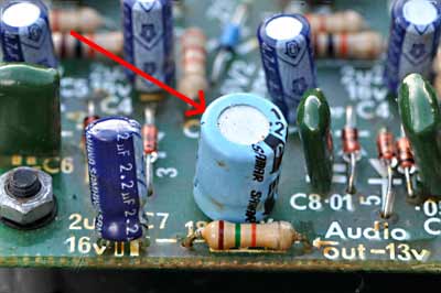
The Three 4·7µF Capacitors
In a unit of this age, and given the relatively small number of low value electrolytic capacitors within it, I decided to eliminate completely any future failures or deteriorating performance by replacing them all with non-polarised film capacitors of the same value, which should last a lifetime.

The 3 ALC capacitors |

4·7µF film capacitors |
In this case, we are looking at the three 4·7µF electrolytic capacitors which are part of the ALC circuitry for each of the three channels, and determine the time constant.
These capacitors sit with around 6 volts or so across them with no audio input, increasing to between 20 & 30 volts with a good level of audio. I had to search around a bit to find some 4·7µF film capacitors which were small enough to fit on the board, but eventually found some 50 volt devices which did, and they also happened to have the correct lead spacing of 5mm to fit the holes, which was helpful.
The situation was helped further by there being plenty of space on the board in that area for these larger components. The removed capacitors showed widely varying values and high leakage; testing the unit with the new film capacitors in circuit showed that the way the lights responded to the music had improved, with the channels having better balance between them so although none of the old capacitors had actually failed, their deterioration was starting to affect performance.
The Four 2·2µF Capacitors
These four small electrolytics lend themselves particularly well to being replaced with low voltage film capacitors, as we only need a value of 2·2µF and this value is readily available as a non-polarised film capacitor which, as with the others, should last a lifetime.
The 2·2µF capacitors |

2·2µF film capacitors |
One of these capacitors is in the part of the filter section which determines the bass output and sits with around 13 volts across it, rising to perhaps 20 - 25 volts with an audio input, suggesting a capacitor with a 50 volt rating or higher. The other three are part of the audio detection circuitry; the voltage across these three capacitors can peak to 4 volts on sudden transients after a period of silence but settles down to between 1 and 2 volts during normal use. Under no-signal conditions, they sit with just 100mV or so across them.
This low polarising voltage suggests that the dielectric may have started to deteriorate over the decades. Because of the minimal cost of replacing these old electrolytics with film capacitors it seems a sensible precaution to take, removing the last of the components which are susceptible to aging.
Used sensibly and with the above changes made, there's no good reason why these little controllers shouldn't continue to function for many more decades without further attention; hopefully the information on this page will be of some use to someone, and perhaps help keep some of these Pulsar controllers 'on the road' for many years to come.
The Things We Used To Do!
It was way back in the mid 70s, and I was a destitute teenager with a wish to run a disco. I was interested in electronics and the dance music of the time, and was also known to have a reasonably powerful 50 watt amplifier which resulted in me getting asked to play music for various house parties.
I enjoyed doing this, so I constructed some purpose-built speakers for the job using two HH B15L 100 watt bass drivers and a compression horn in each cabinet, and borrowed for an indefinite amount of time a powerful amplifier of perhaps 200 watts a side to produce the noise. I constructed a twin-deck console sporting a pair of BSR P200 decks obtained from the long-gone Electrosure in Exeter, who also supplied me with a second-hand mono unbranded mixer; I now had the beginnings of a real disco and had the capability to play music at hideous sound levels!
My Light Boxes
At this point the only lighting I had was couple of triple spotlight banks powered of course by a little Pulsar Zero 2250, which I'd managed to get second-hand from a local disco shop for a tenner. I needed some light panels across the front of my disco, so for this I built 6 vertical light boxes made out of chipboard, each with five 40-watt bulbs inside which had been dipped in red, green and blue lacquer.
The boxes looked pretty rough even though they were painted black, and it wasn't long before I upgraded them by fitting a piece of plastic shower screen over the fronts to diffuse the light and to protect the bulbs, which improved the appearance a lot; 'cracked ice' was the texture as I recall.
These light boxes were powered by another Pulsar Zero 2250 unit; I initially hired this second controller, but it slowly dawned on me that the shop hadn't taken a name or address, so I never quite got around to returning the unit. I am, of course, very ashamed of myself, and if the company was still operating, I'd consider taking it back but they aren't and so I can't. However, I digress; the six light boxes actually looked quite effective when flashing, with three panels on each side, with each side a mirror image of the other and wired up in order of bass, middle and treble.
To begin with, each of the six light boxes just had a lead coming from them, and as I didn't then have the correct socket to fit the controller, the wires were simply bared at the ends, bunched together in pairs and the bare wire shoved in the socket on top of the controller. It was sort-of reliable, and my mate used to joke about the 'bird's nest' of wires poking in the top. Occasionally they'd have to be pushed back into the socket if one of the boxes stopped working, and the collection of wires had a habit of sparking quite a lot.
Elfin safety, wassatt then??
A later refinement involved mounting the lighting controller's circuit board inside the deck console and fitting small sockets, 3 on each side, for the light boxes, thus finally getting rid of the temperamental and potentially shocking bird's nest.
I continued to use the format of 6 vertical light boxes right up until I gave up doing discos, although they went through several alterations and improvements over the years, the earliest and most notable when I moved over to a sheet of coloured gel rather than the crappy coloured bulbs; changing bulbs at that time was done by carefully lifting the plastic front and sliding it up to expose the bulbs.
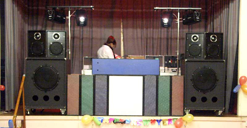
My disco setup, New Year's Eve, probably late 90s.
In the photo above you can see the 6 narrow light boxes with a centre panel between them, and my daughter playing some background music. (We won't discuss my super-duper home-built Fane-driven 3-way biamped sound system here, as it's not the topic of discussion.) Although un-powered when the photo was taken, the light boxes lit up bright red, green and blue and were positioned as mirror images; despite the lack of creativity on my part, they actually looked very effective as a front-piece and early on in a gig, it was common to see people sitting and staring at the lights, apparently hypnotised by them.
When setting up to do a disco, it was routine to do a quick visual check of the bulbs in the light boxes which between the 6 vertical boxes and the centre panel, amounted to 42 bulbs. I would typically be replacing around three blown bulbs each time, which I considered excessive. In an effort to reduce this, I incorporated a 30Ω high-wattage series resistance made up of two 15Ω resistors in series in each box to limit the switch-on surge current, and this worked superbly, making bulb replacement the exception rather than the norm, with most now lasting several years. (I used to write the installation date on the base of the bulbs so I could keep track of how long each one lasted.)
Fairly soon after this photo was taken, those old light boxes were scrapped and new ones built out of plywood having been completely redesigned, this time with a fixed front panel, a hinged rear to facilitate bulb changing, carrying handles and a nicer patterned polycarbonate front among other changes. Still powered by a Pulsar Zero 2250 of course.
A Most Unlikely Repair
I had developed a small reputation locally as someone who knew a bit about electronics, and although I didn't normally entertain messing around trying to repair other people's stuff, I felt I had to have a look when one my acquaintances brought round a Pulsar Zero 2250, as it had "stopped working".
I was already familiar with this unit as I had a couple of my own; despite having 'no user serviceable parts inside', I suspect this guy had opened the unit up, and believe it may well have been at least partially working before he got into it.
Looking at the mess of blackened circuit board and vapourised traces, my personal suspicions are that a multimeter had been used between the neutral connection and another part of the circuit, but rather than volts, current had been selected (we've all done that at some point, right?), which would certainly explain the damage. Whatever the cause, I immediately decided it was beyond economic repair and told him so.
He looked a little sheepish as I was giving him the verdict, lending weight to my theory that he'd somehow created the problem; he said if it was any good for bits, I could have it, and he'd go and get a new one. As it had a decent case, I decided to hang on to it and bunged it in the junk box.
Many years later I felt in need of a challenge and got the old wrecked Pulsar Zero 2250 out. The damage to the board was considerable so I set about removing 9 diodes and all 14 transistors from the board on the sensible assumption that they had been destroyed; the two inverse-parallel diodes fitted to the output of the isolating transformer were still OK so were left in position. Out of the 14 transistors, only 3 still tested good, those being the ones involved in the audio amplification; I suppose this low survival rate was to be expected given the scale of the carnage.
I began some basic tests and after replacing the 6·2 volt Zener diode and its associated 1N4148 diode I managed to get the power supply section functioning and supplying the correct voltages on the three rails.
One of the resistors (47Ω to bass triac gate) had blown its pants off and unsurprisingly tested open-circuit, so I tested every resistor on the board, and found the rest to be good which was surprising. All capacitors tested OK as did the three triacs, which was even more surprising.
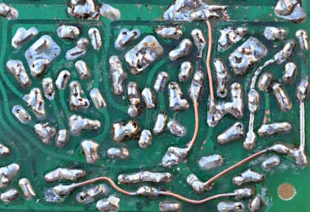
Repaired PCB tracks
The next step in the repair was to clean off as much of the blackening from the board as possible and to re-build the burnt tracks with copper wire; this is a delicate procedure and never worth the bother unless, as was the case here, it's your own time and, for the moment, you have nothing better to do.
Transistors used in this unit were BC547Bs & BC557Bs, and as I had a good stash of these, I fitted all new to the board, leaving them on long legs so that should the unit not work after attempting the repair, it would allow me to re-use them; I then fitted new diodes in place, again leaving the leads long, and prepared to apply power via an isolating variac. As I turned up the voltage, I checked the readings at various points and all seemed well so I stood well back, put my fingers in my ears and applied full mains voltage to the unit.
There were no puffs of smoke or explosions, and in fact nothing exciting happened at all; with bolstered confidence I moved on to the final step, which was to attach some lamps and apply sound. At first, the lamps didn't flash; with my previous confidence now down the toilet I carefully checked all the connections and discovered that I hadn't connected the controller to the amplifier properly. I powered everything up again and this time, to my utter surprise and elation, the little old Zero 2250 sprang into life, flashing the lamps for all it was worth.
I still have that little Pulsar Zero 2250, and because of the sheer amount of time I spent repairing the thing it now holds a special place in my collection. OK, the circuit board looks like it's been through a nuclear holocaust, but the case is in good condition and above all, it's still alive!