Center-fed Bent-Dipoles
Horizontal Lateral
Vertical
- OCF
Slow-Wave
Other Topics
Home
To get a low Standing Wave Ratio (SWR) over a wider frequency range (Band Width), a larger antenna radiator is used. Thin wire becomes thick wire or tubing or multiple wires (cage dipole, fan or bow tie shapes)..
You Bend the Ends Into Triangles?
The first thing that changes is the resonant frequency; it is lower. It can be a lot lower depending on the fan angle used. To correct for this the antenna must be shorter.
These features of band width and shorter length are attractive to antenna designers. Early literature is replete with information on theory, dimensions, construction, impedance matching and stories of antenna performance.
The early fan thinking apparently was about increasing the amount of radiating surface area of the ends of a dipole. As might be expected a number of disparities arise when comparing the older ideas such as: Each bow should be ¼ wave length long. Impedance is typically 100 to 400 Ohms. Gain was sometimes thought better than a straight wire dipole.
The angle was not defined and height was thought to be the way to control bandwidth. The antenna was not resonant. Impedance was handled with 300 or 450 Ohm feed line and a matching device.
With the rise of high definition television (HDTV) and very high frequency usage (WiFi, Bluetooth, etc.) there was a new interest in suitable antennas. The modern literature from this work has benefitted from the creation of antenna modeling software. With the development of mainframe software in the 70’s and PC software in the 80’s, all that thinking has changed.
To study the characteristics of the Bow Tie Dipole an updated version of the L. B. Cebik, W4RNL (SK) model was created in the 4NEC2 program using symbol variables rather than fixed numbers. This allows automatic optimization to find the best value for parameters such as length, width, feed point elevation, SWR, impedance and reactance.
In addition, a series of internal calculations are imbedded to determine Total Width of the dipole, Percentage reduction in Width, Included Angle of the triangle, Total length of wire needed for construction and convertion of Meters to Feet.
To be directly comparable to all other standard “Bent Dipoles” models, feed point elevation is one-half wavelength over Average Ground. Wire is #14 AWG. Results are validated by the Average Gain Test (AGT).
The Bow Tie Dipole 4NEC2 model is included here for study and to make adjustments in Length, Height, Wire size, Feedpoint Gap an Feedpoint Elevation to better suit a particular situation.
Click Here for Model
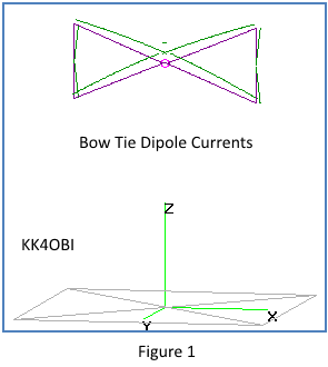
One of the first things noticed in developing the model is that the ends of each triangle must be defined as two wires. Single wires do not work.
Looking at the currents (green lines) in
Figure 1, the
antenna can be regarded as crossed half-wave dipoles with the ends bent
towards each other. Refer to "Horizontal Bent end dipole" in the Navigation Menu
The ends do not even
need to be connected! It
makes no
detectable difference. If the four end wires can pivot or bend
they can be used for tuning. When the Bow Tie frequency is too
high, angling the end wires outwards lengthens the the antenna.
By this adjustment resonant frequency can be lowered up to 10% by
changing the angle in range of 180° to 150°.
Caution.
The reverse is critical. The need for a small rise in frequency demands
radical changes in the "fold-in" angle. If possible, it is better to
decrease the fed point gap to shorten the antenna.
In fact, only the two upper ends need to be
used. Surprizingly, with all four ends pointing up the match is as
good as the ends pointing towards each other.
The ends even can be eliminated and the length and angle of the wires adjusted for resonance. This open-end configuration is commonly seen in stacked HDTV antennas.
Below are the model predictions when the
length and height of
the two bows are systematically changed to give the best SWR and
reactance (j).
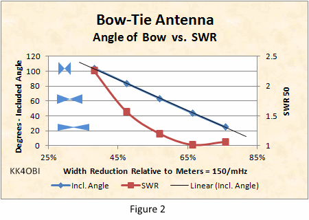
Look at the Standing Wave Ratio (SWR) curve (Red line). At the Included Angle of 44° (Blue line) the SWR is lowest. At this point the dipole is 66% shorter. From the graph it can be seen that the antenna width can easily be shortened to 50% or less and stay under a SWR of 2:1.
The relative height of the bows is indicated by the blue figures in the graph on the left. The associated graph of Included Angle (Blue line) is extended by Linear Regression. If the angle goes to zero, the antenna becomes a straight dipole with a SWR around 1.4. As the bow height exceeds 100° included angle, the impedance falls rapidly and the SWR becomes extremely high.
Note: Width is expressed as percentage of the length in meters of a half wave. This is for scaling the Bow Tie Antenna to a frequency of interest. See footnote for details.
.
How does a
Bow Tie Antenna compare with a Straight dipole?
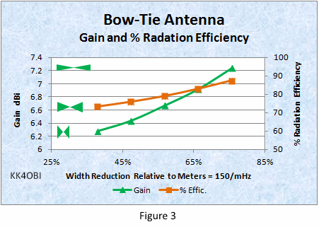
RULE: the shorter and taller the Bow Tie shape (Green figures on the left), the lower the Gain (Green line) and % Radiation Efficiency (Red line). That is the cost for increased bandwidth and decreased length.
It is inferred that, as the antenna width approaches that of a straight dipole (100%), Gain (Green line) and % Radiation Efficiency (Red line) approach that of a straight dipole. (No data. NEC2 software cannot handle acute angles.
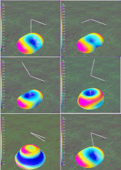
The 4NEC2 modeling program provides 3D
graphics that include individual Vertical, Horizontal and Total
radiation patterns. 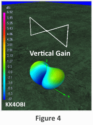
Because
of the Bow Tie antenna has vertical ends, it is interesting to look at
the Vertical Gain component as shown in the Figure 4.
It can be seen that there is a small radiation contribution of off the
ends of the Bow Tie directed slightly upward depending elevation from ground.
[Gain is indicated by the color scale on the left side. Magenta
is strongest. Blue is weakest. Yellow/Green is “unity gain”].
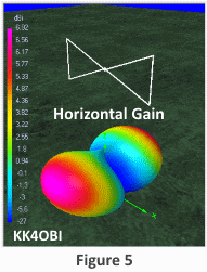
Gain is greatest broadside as indicated by Red/Magenta coloring. Take-off-angle is 30°.
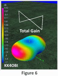
Total Gain as seen in Figure 6 combines both patterns to produce weak nulls and broader dipole radiation due to the mixed polarity.
As the Bow Tie ends get taller, the Vertical component increases:
- The radiation pattern gets broader..
- Gain (dBi) and % Radiation Efficiency decrease.
As the Bow Tie ends become shorter, the Vertical component decreases:
- Gain (dBi) and % Radiation Efficiency increase.
- The radiation pattern becomes more like a conventional dipole.
When a Bow Tie Dipole and Straight Dipole are tuned to their lowest SWR range, the Bow Tie will have about twice the SWR band width as the Straight dipole, around 8% versus 4% respectively.
The fundamental differences are:
- The shape of the SWR curve. A shallow curve means wider bandwidth.
- How low is the SWR. The closer to 1:1 SWR, the wider the band width,
A Straight dipole typically has a relatively
narrow curve and can only be tuned to 1.3 to 1.4 SWR.
Conversely, the
Bow Tie has a wider curve and can achieve close to a 1:1 SWR.
Here are the best case examples to compare:
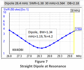
A standard Straight Dipole at 28.4 mHz has a minimum SWR of 1.38:1.
At a reference point of 30 mHz the SWR is 3.564.
The difference in SWR at the reference point is 2.18. This is a relatively large drop indicating a relatively narrow SWR curve.
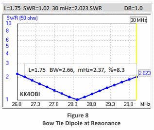
In Figure 8
A standard Bow Tie Dipole at 28.4 mHz has a minimum SWR of 1.02:1.
At a referenve point of 30 mHz the SWR is 2.023.
The difference in SWR at the reference point is 1.0. This is a relatively small drop indicating a relatively wide SWR curve.
If SWR curves are normalized to a perfect 1:1 ratio we can directly compare a Straight Dipole to a Bow Tie Dipole. The five % widths used in the graphs of antenna characteristics, Figure 2 and Figure 3, are examined in Figure 9 below.
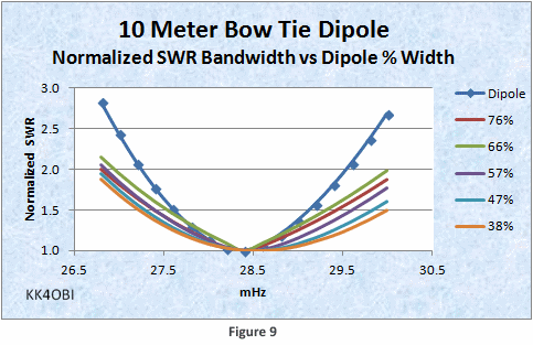
Modeling reveals that the theoretical SWR band width is greater at the higher frequency end as the Bow Tie antenna width is reduced. In the real world of variable SWRs this trend will not be very noticeable relative to the 2:1 SWR limit. A guideline of +/- 1.5 mHz at 28.4 mHz is good enough.
The practical implication is that the Bow Tie Dipole can be half the length of a straight dipole and be tuned for use over the entire 10 meter band… even including CB channels.
Footnote
For scaling to a frequency of interest, the widths in Figures 2 and 3 are expressed as a percentage of a half-wave of the frequency of interest using the formula: Meters = 150/(mHz frequency).
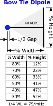
For example: For 10 meters at 28.4 mHz a half-wave length is 150/28.4 = 5.28 meters. To reduce this to a Bow Tie antenna that is 60% wide, multiply 0.6 x 5.28 = 3.168 meters wide. Each Bow half is therefore 3.168/2 = 1.584 meters wide.
From the adjacent table the corresponding % Height for the vertical ends is around 33%. Multiply 0.33 x 1.584 = 0.523 meters high by 1.584 meters wide
The feed point gap used for the prototype antenna was around 6 inches between the ends of each triangle. For tuning purposes the gap can be adjusted. Narrower to raise frequency; wider to lower. Also, tuning stubs can be extended from the center of the vertical element of each bow.
Finding dimensions based on the Included Angle at the feed point is a bit more involved. From the discussion of Figure 2, 66% width reduction is 0.66 x 5.28 = 3.486 meters wide. The Included Angle at the feed point is 44°.
To find the width and height of these trianglar bows at 28.4 mHz:
- the bow width is half the dipole length. 3.486/2=1.743 meters wide.
- the angle needed for calculation is half the included angle.
44°/2=22°.
- the needed of half bow height is calculated: 1.743 wide x tan(22°) =1.743 x 0.404 = 0.7042 meters half height.
- the end of the bow is doubled. 0.7042 x 2=1.4084 meters high by 1.743 meters wide.
Dick Reid, KK4OBI at qsl.net

