CMT R54 Source Power
When measuring the input impedance of active items/inputs, it is important to know what the applied power to the Device Under Test (DUT) is from the test equipment. This post covers measurement of the output/applied RF power from a Copper Mountain Technologies (CMT) R54 Vector Impedance Probe to ensure it is known, so as to not overload or damage any given DUT connected.
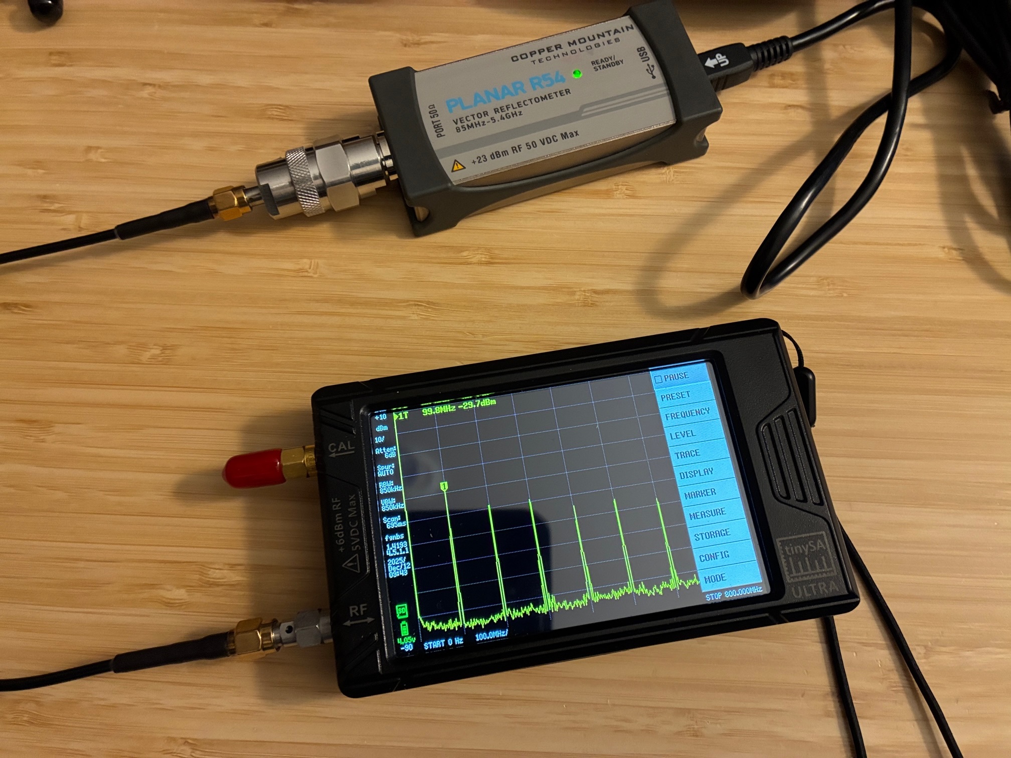
The CMT R54 software provides a two state power level setting with the device specifications listing a value of -10 dBm for High and -30 dBm for Low. A TinySA-Ultra was used to measure the power level with the R54 set to a very narrow span (practically zero span). A frequency of 100 MHz was chosen for this test (may be repeated later for additional frequencies as time permits).
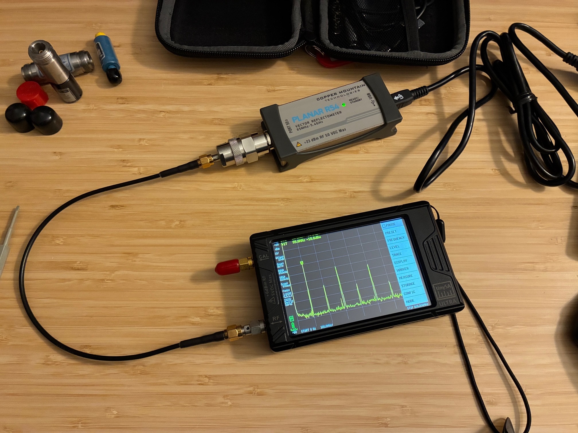
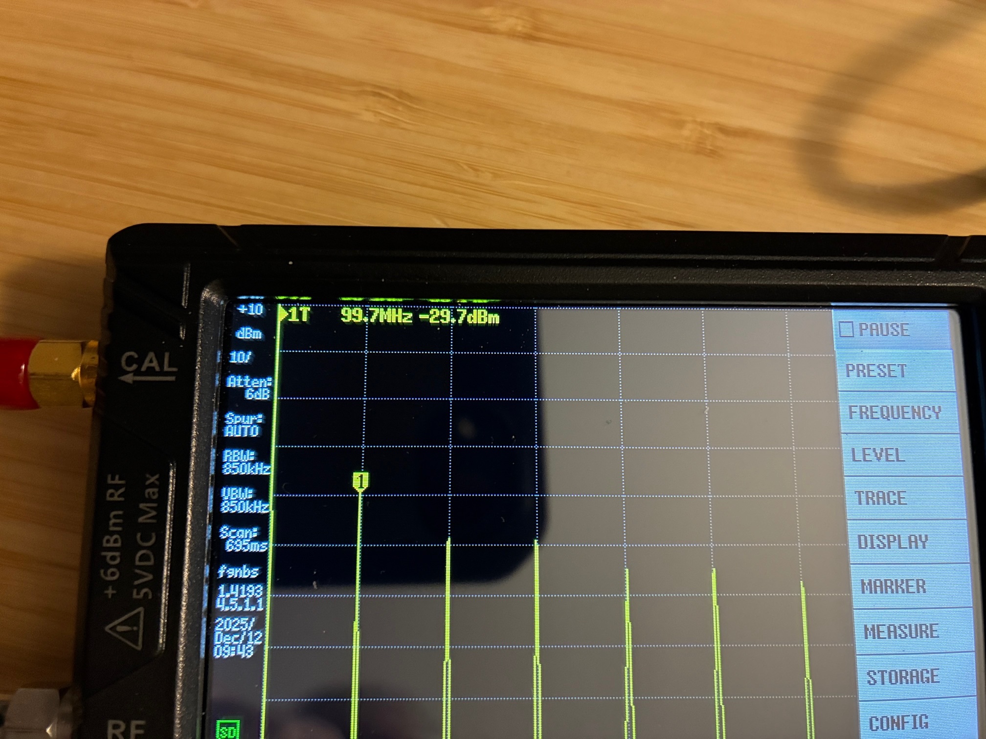
First up is measuring High power. The software setting is shown below, followed by a zoomed out view of the test setup, and finally a zoom in on the TinySA screen showing the marker level of the R54 probe's output.
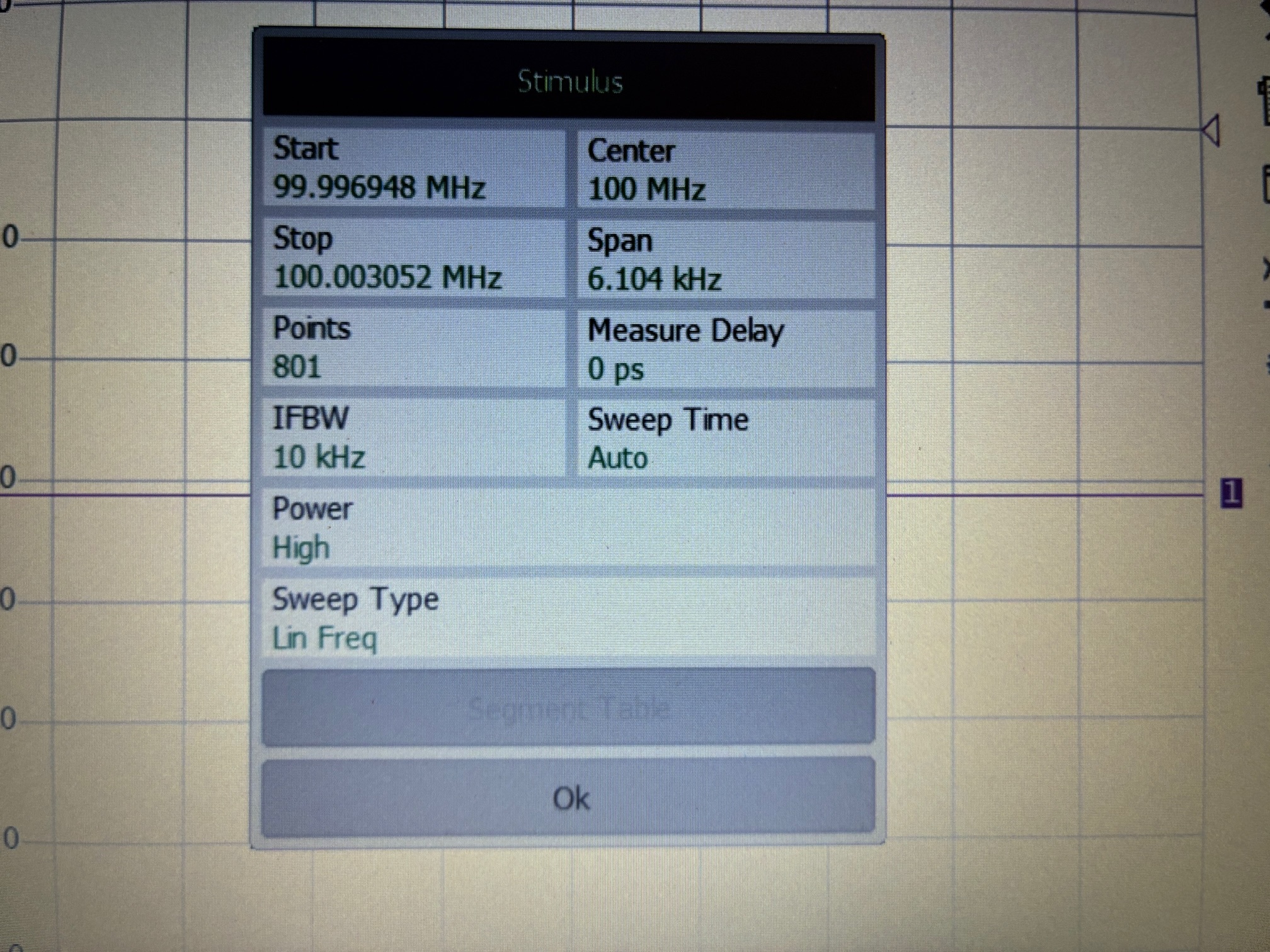
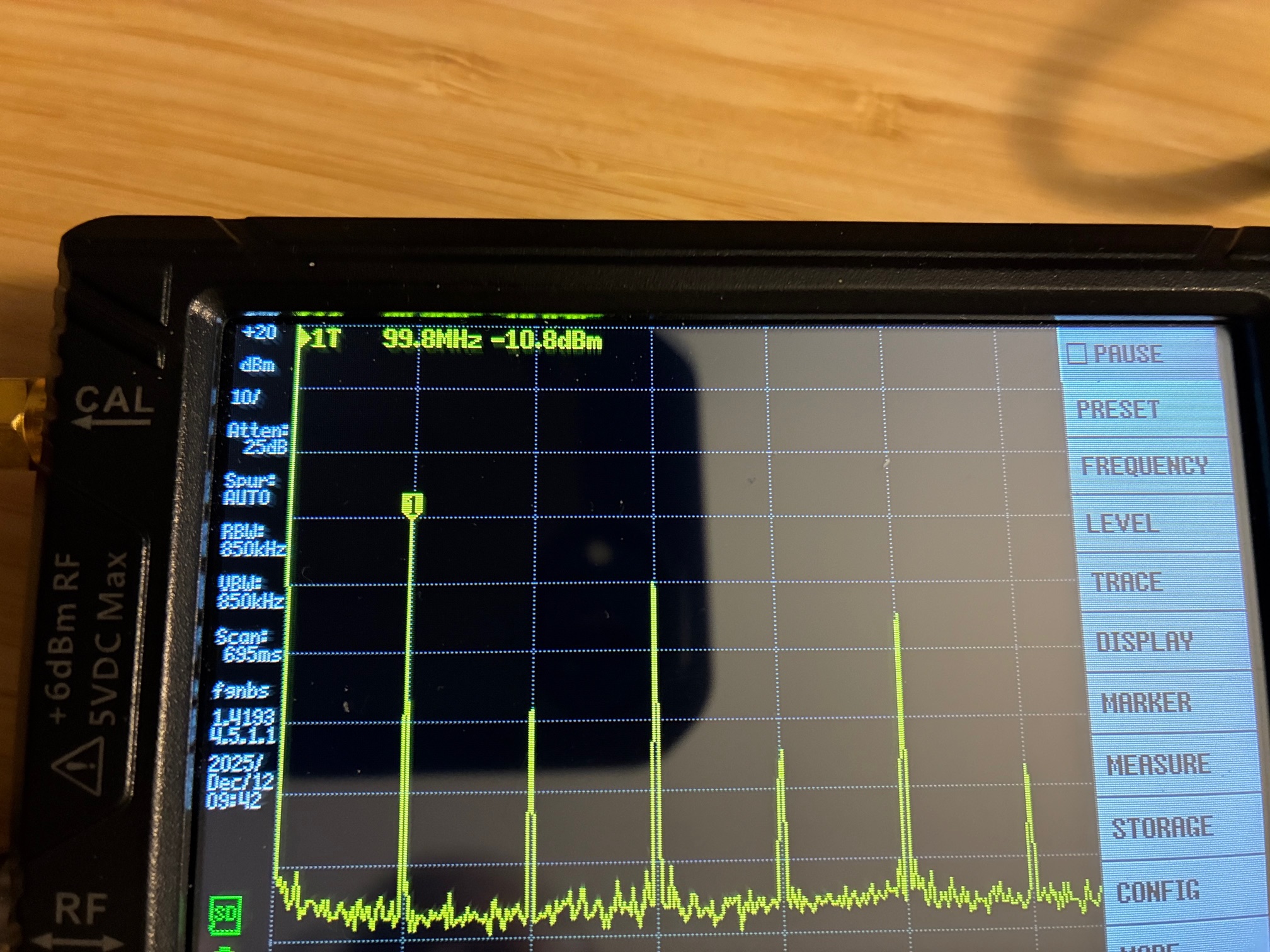
The High output setting matches the specifications sheet. The TinySA also shows that the output RF test signal is a square wave.
Let's repeat the test with the Low output setting (and using the same photo sequence).
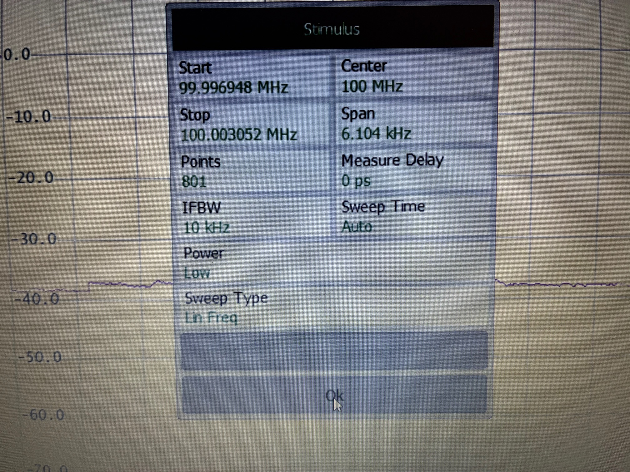
The Low output setting matches the specifications sheet as well.
This concludes the test of this vector probe's output power level. With these values known, the R54 probe can be safely connected into a test system (using attenuators of proper values).
At a future date, this same measurement should be conducted for the NanoVNA-H4 vector analyzer. A quick search did not turn up a definitive specification for the output level of the NanoVNA. (Thought to be around 0 dBm?) Will measure my unit and then the output level will be known for future use thereafter...
All author photos taken with an iPhone 16e.