Stand Alone RF Power Meter
With the LabVIEW based RF Power Meter completed, the thought to create a stand alone benchtop RF level meter came into focus. Using the Mini-Circuits ZX47-55LN detector connected to a Win11 PC via the lab's Digilent Analog Discovery 3 (AD3) module seemed to be overkill for just monitoring the RF level at a point in a system.
The thought was to take a small embedded processor board, add a two line text display, and connect the ZX47-55 to it via an analog interface. Run it off of a wall wart DC (ideally +12V) module, and just plug it in and hook it up to RF when needed. Sounds simple right?
Trying not to reinvent the wheel too much, a quick search for "ZX47-55" and "Arduino" revealed this helpful github site: https://github.com/dl9sec/Arduino_RF-Powermeter. This project used the same Mini-Circuits sensor with an Arduino UNO with a prototype shield on top holding the sensor interface wires and a 4-line multi-color Waveshare 0.96" 128x64 OLED SPI/I2C display. The project used three separate pushbuttons for control functions.
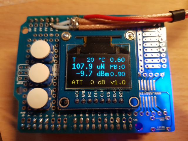
Above photo is of the DL9SEC RF Power Meter from the author's github site.
This looked like a good starting point with just editing the shared Arduino .ino code to work without buttons and with a two line display rather than the OLED used in DL9SEC's project. How hard can it be?
With hopes of only minor code changes to be made to an Arduino-based solution, the decision on what processor board/display would be used was next...
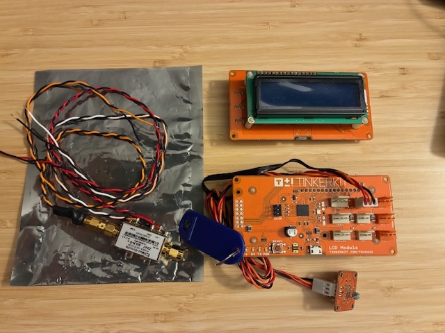
Looking through the Embedded Processors / Development Kits electronics box yielded two in-hand HW platform candidates. First was a TinkerKit LCD display based solution. This was a 2-line display on the back side of a Leonardo-based processor board. There are a number of pin jacks available for analog inputs and digital in/out connections. The photo below shows the basic module in the upper right, with the lower right an example of connecting an external thermistor to make a simple thermometer display. There are no user buttons pre-connected or configured with this approach. The TinkerKit board can operate stand alone running code on the local processor or connect as a wired I2C remote display to another processor board.
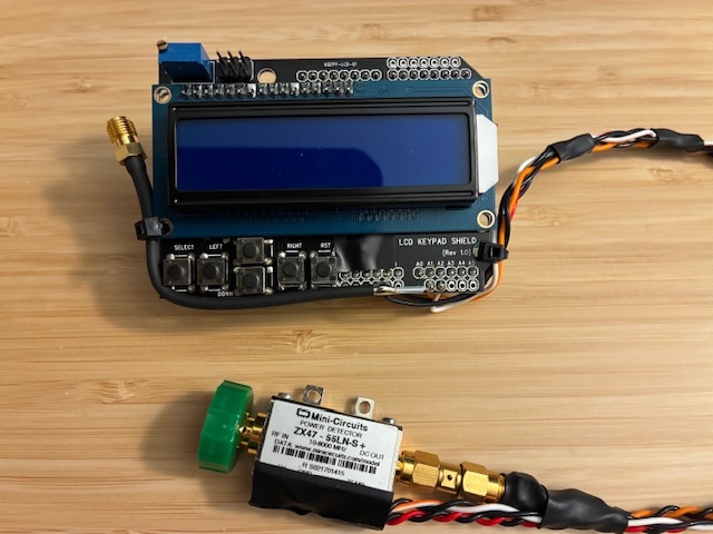
Next up is a classic Arduino UNO R3 board with an add-on OSEPP display/button shield.
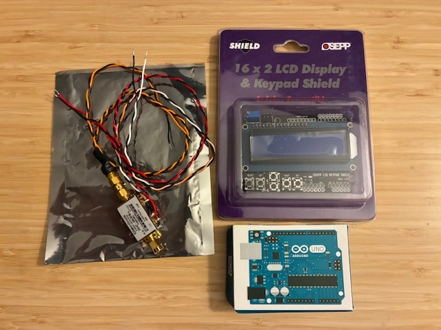
While both hardware approaches meet the requirement to operate as a stand alone processor display, the UNO with OSEPP display/button shield offers a growth path to adding new features requiring user input (i.e., buttons). The decision was made to proceed with the second approach. Time for wiring and coding!
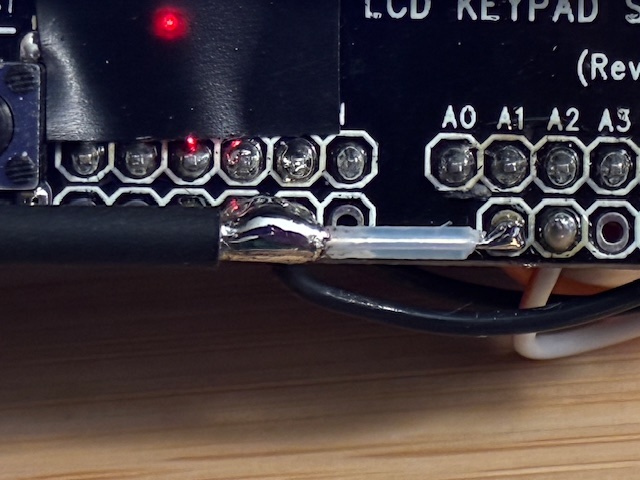
Reading through the DL9SEC .ino file showed a conflict on the analog input connections, where his project used analog input 0 and 1 for temperature and power, and the OSEPP display/button shield using analog input 0 for the button/key input line. The temperature input was moved to analog 2 input connection on the UNO. The decision was made to wire up the ZX47-55 sensor to the OSEPP display shield rather than adding an intermediate prototyping shield for the Mini-Circuit sensor's connections.
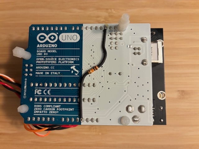
The original project rescaled the A/D inputs by changing to an external reference voltage instead of the larger range internal scale through addition of a 10K Ohm resistor from +3.3VDC to the External Reference Input pin on the UNO. This was best implemented by just adding the needed resistor directly on the back side of the UNO board. Sleeving was installed on the resistor leads to minimize risk of creating any shorts on the UNO board.
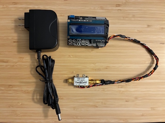
With the connections finalized, the Mini-Circuits ZX47-55 was wired to the OSEPP display/keyboard shield. A +12VDC wall wart adapter was identified to power the system via the UNO's external input power jack. The sensor's connection wires were twisted and kept reasonably short (but not too short at 12") to minimize noise pickup in use.
With that, code review started (and wishing that I knew how to program Arduinos as well as I know how to program with LabVIEW). After setting up a new project, reviewing how to write to a LCD display, and reading through DL9SEC's .ino code MANY times, I was able to get a working temperature display.
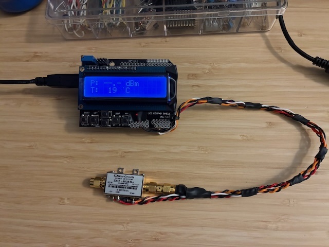
The RF power display has a default reading for no power applied (less than -55 dBm ideally), so the above photo really only provides an indication of the lab temperature at that moment.
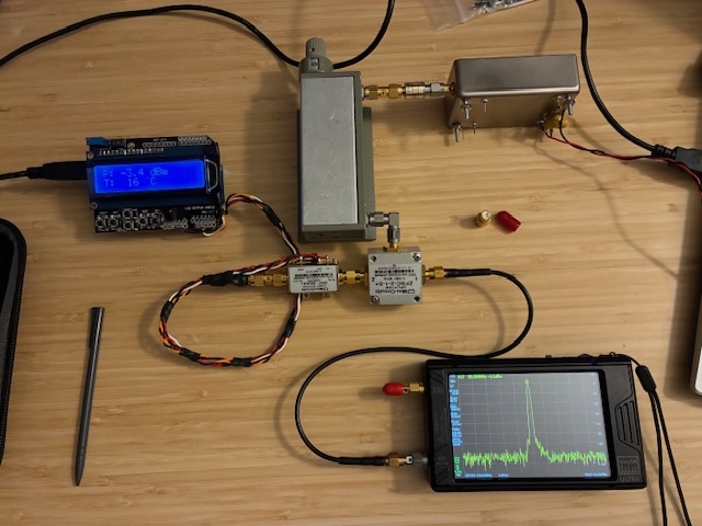
The same RF level test setup was used for debug and calibration as with the LabVIEW RF Power Meter version. This starts with a +13 dBm 100 MHz RF oscillator, then connects a 10 dB pad, a 0-70 dB 10 dB step attenuator, and a two way splitter. The final splitter's outputs are approximately 0 dBm when the rotary attenuator is set at 0 dB. This setup provides a known level from 0 dBm down to -70 dBm.
This project's revised code starting point was modified to properly output both temperature and RF level to the new 2-line LCD display. A simple splash screen was added to the start up sequence. A guess is that 30% of the code was touched, rewritten, or modified in some way.
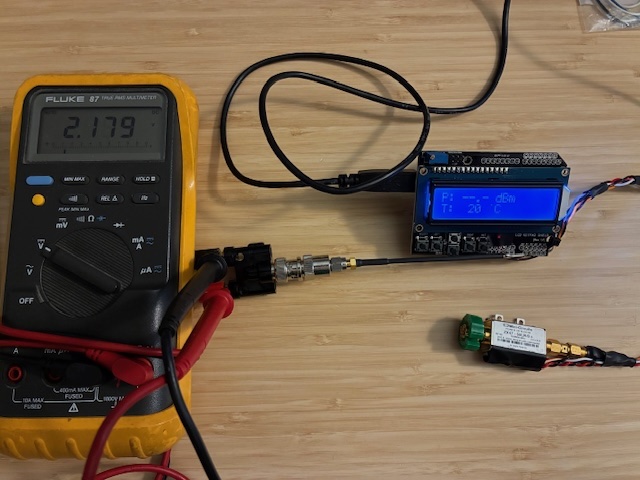
The magic numbers used in the code were found and tweaked to "calibrate" RF level and temperature of the new system. When the RF levels were close enough, a verified temperature sensor was connected to the ZX47-55 module to "calibrate" the temperature output on the display to match the known accurate 1-wire USB sensor (within a degree C). The wired temperature sensor was taped onto the ZX47-55 module for this test and left to stabilize with the system running at room temperature.
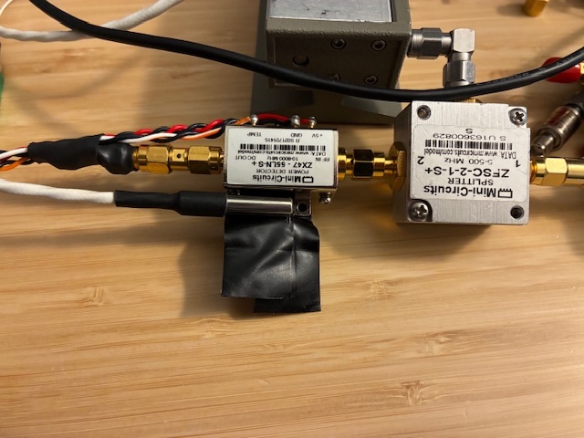
Below is a somewhat messy setup showing the thermal sensor attached to the ZX47-55 module, and lots of wires running across/through the setup. Waiting for things to thermally stabilize...
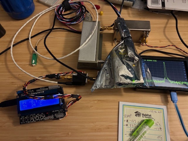
The 1-wire USB thermometer / thermal sensor used for this calibration is described in a previous post. These work very well and are tough enough to survive everyday laboratory use.
With all the magic numbers identified and tweaked, the resultant stand-alone RF power meter seems to be within 1 dB over the +5 dBm to -55 dBm input power range, and is within half a degree C at room temperature.
A set of plastic snap-in feet were cut and installed to tilt up the display towards the user. With that, this project is complete.
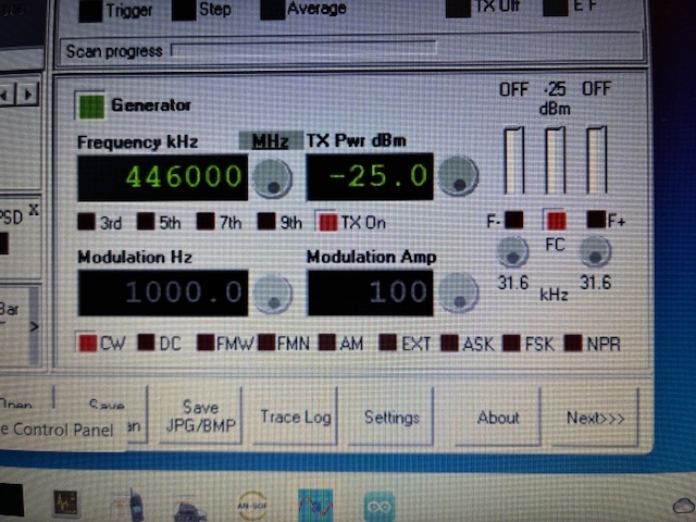
Let's try it out to make a typical measurement. Scenario: Want to check the RF output level of a ADALM PLUTO SDR. The SDR is controlled via SATSAGEN on the Win11 PC. Generator function is enabled. Mode is CW (continuous stable output), the frequency is 446.000 MHz, and the output is enabled (TX On). The ZX47-55 is connected directly to the Pluto TX port (via the standard 5 dB pad always connected there and allotted for in the output level adjustment via SATSAGEN). Am expecting to see -25 dBm on the stand alone RF Power Meter...
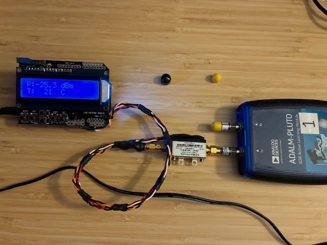
It's a little hard to see via the camera photograph, but it's clearly reading -25.3 dBm on the RF Power Meter. Have confirmed that this Pluto SDR transmitter output is working properly!
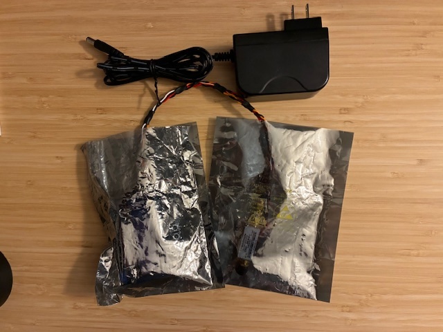
Nothing fancy for routine storage of this new lab functionality. ESD bags and labeled zipper pouch for the win.
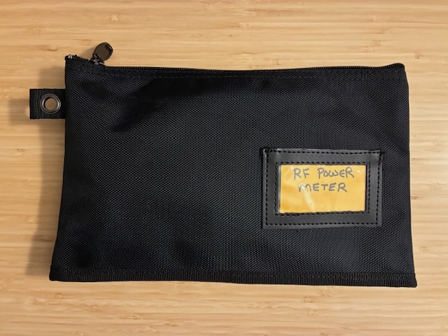
Achivement Unlocked (stand alone RF Power Meter)!
Next steps are to use the meter in the lab regularly and keep track of any thoughts towards future enhancements. Those buttons on the display are sure to come in handy at some point. A few thoughts:
- How about a fast-reading mode instead of the current ~1 Hz update rate?
- Or turning the second display line into a giant bar graph indicator?
- Or press a button for a relative level reading mode?
- Or adding a virtual serial port over USB for temp and RF level data output to a PC & LabVIEW for further processing/storage?
- COMPLETED: Or a detected power level output to a SMA jack to hook up to a scope or meter for real-time/faster observation of signal level changes (such as AM modulation, RF pulses, etc.)?
- How about duplicating the project using a COTS $15 USD RF power log detector instead of the expensive Mini-Circuits ZX47-55 sensor? That might get total cost down to less than $50 USD. Will look into sourcing one of these and give it a try...
More fun ahead!
If anyone is interested in duplicating this project, please reach out and I'll gladly share a copy of the .ino file for today's Ver 1.0 RF Power Meter.
Author photos taken with an iPhone-16e.