LabVIEW RF Power Meter
Have had a spare Mini-Circuits ZX47-55LN RF Detector module in the misc. RF modules box for a while now and having recently sold off my HP/Agilent RF power meters/sensors, wanted to put the little ZX47-55 detector to use as a RF power meter in the home laboratory.
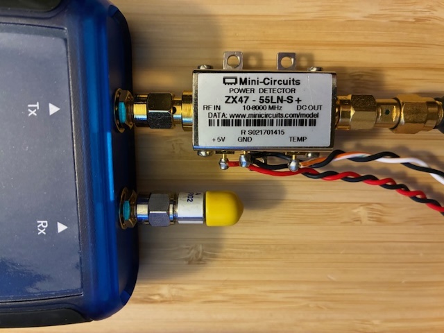
The first step was to determine if it was working correctly. The sensor module runs off of +5V (~100 mA) and has two analog voltage outputs (RF power level and temperature). A quick test with a +5V DC power supply and my Fluke multimeter showed that the DC RF power level voltage varied when attached to (or disconnected from) my Pluto SDR generating a test signal at 100 MHz. DC output level changed with RF input levels. It works!
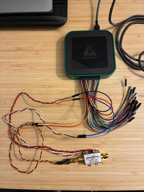
With that known, flying wire connections were made to control and monitor signals using my Digilent Analog Discovery 3 (AD3) USB "bench of test equipment in one box" module. This test used the AD3's two scope/voltage inputs to monitor the RF level and temperature analog outputs with the AD3 supplying the needed +5VDC power to the sensor module.
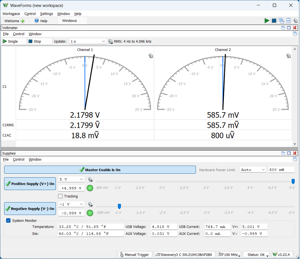
Using Digilent Waveforms software yielded this test sceen. The left meter is the RF level, and the right meter is the temperature output. The power supply control screen is below (providing +5V to the sensor).
The next step was to write a LabVIEW controller to 1) control the AD3 +5VDC output voltage, 2) read the RF power level analog output voltage and convert it to dBm/Watt, and 3) read the temperature output analog voltage and convert it to Deg C and Deg F.
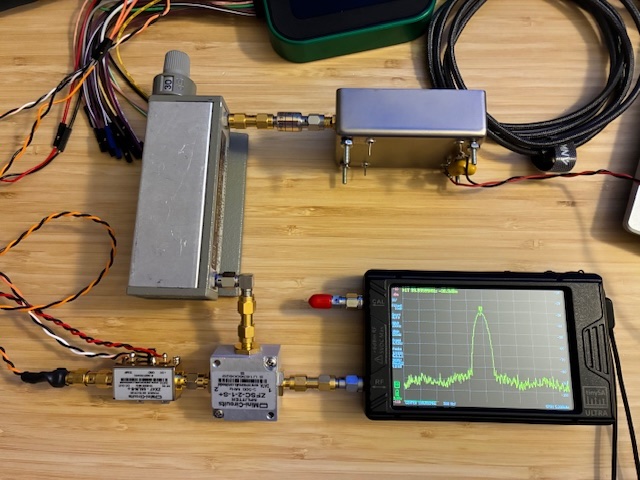
As part of this activity, a variable RF level test setup was put together to be able to test the sensor's DC output at multiple RF input levels. This used a 100 MHz +13 dBm test oscillator, a 10 dB pad, a 0-70, 10 dB step attenuator, and a 2-way RF splitter providing two test signal outputs. One test signal went to the TinySA-Ultra spectrum analyzer. The ZX47-55 sensor was applied to the second test port.
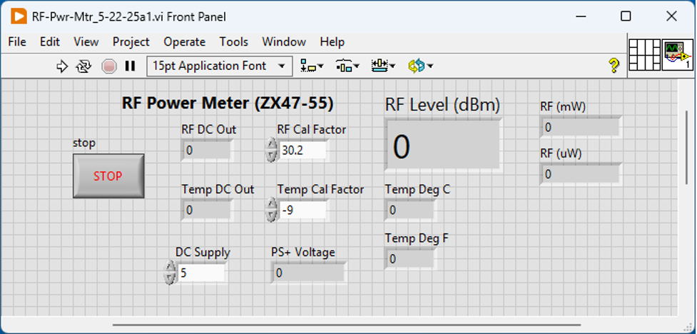
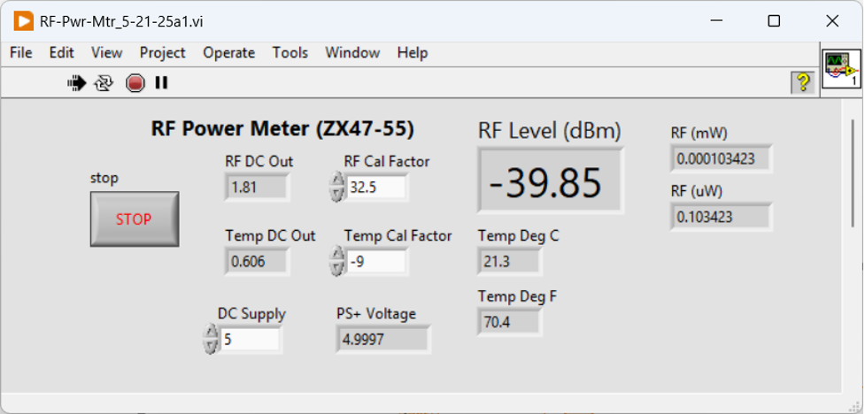
The goal of the software development was to provide dBm, Watts, Deg C, and Deg F outputs over the maximum possible operating power level range (ideally +5 dBm down to ~ -55 dBm). LabVIEW Community Edition (free) was used to write and run the virtual instrument (VI). Below is the front-panel interface for the VI.
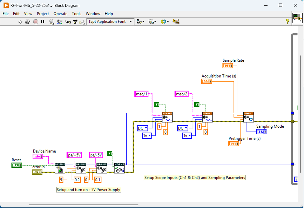
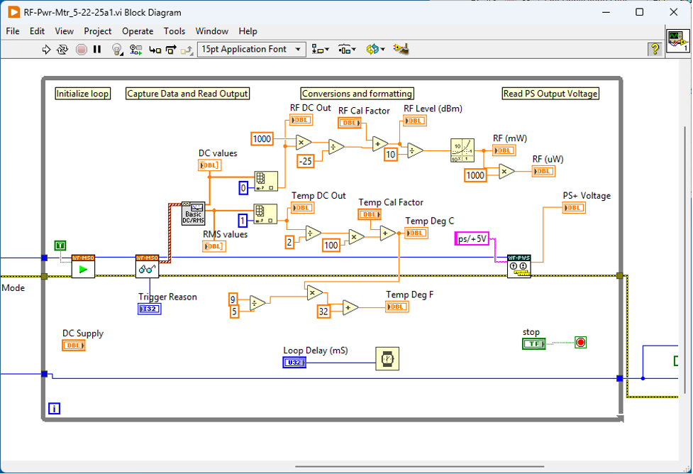
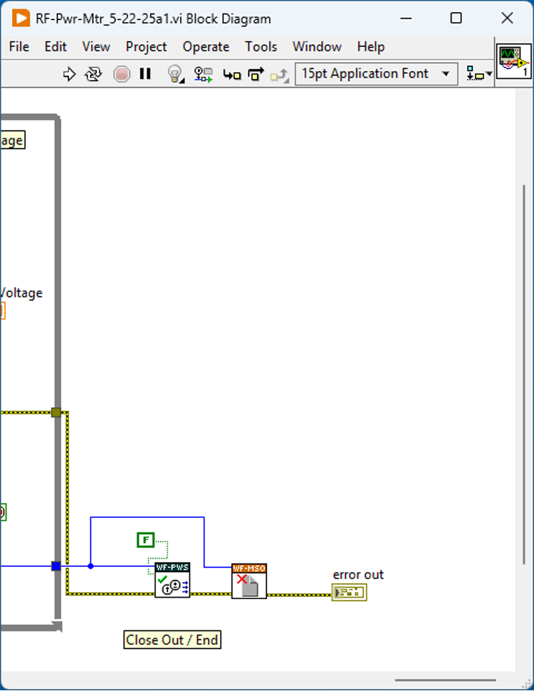
The diagram showing the VI "code" is below in three parts (left, middle, right).
Finally, here is a captured screen shot of the ZX47-55 measuring RF power (and temperature) using LabVIEW/AD3 and the multi-RF step test setup at 100 MHz. This specific test had an input level to the sensor of -40 dBm. Pretty close!
With the sensor working on CW signals over the +5 to -50 dB input range, this completed the DIY RF Power Meter project for the moment (with recognition that it needed both the lab's Win11 PC and the Digilent AD3 module to operate).
The next thought was: What if there was a way to easily use the ZX47-55 sensor without needing the AD3/Win11-PC along side? Operate stand-alone?
This pointed to the next possible project: Create a Stand Alone RF Power Meter that could easily be placed anywhere on the test bench, that would provide CW power monitoring capability...
Author photos taken with an iPhone-16e.